
Subscribe to Our Youtube Channel
Related Manuals for Perkins 4012TESI Series


Summary of Contents for Perkins 4012TESI Series
- Page 1 TSL4187E, Issue 1 February 1998 User’s Handbook Perkins 4012 and 4016 Gas 4012TESI 4016TESI...
- Page 2 WARNING READ AND UNDERSTAND ALL SAFETY PRECAUTIONS AND WARNINGS MENTIONED IN THIS MANUAL. IMPROPER OPERATION OR MAINTENANCE PROCEDURES COULD RESULT IN A SERIOUS ACCIDENT OR DAMAGE TO THE EQUIPMENT CAUSING INJURY OR DEATH. NON-COMPLIANCE WITH THESE INSTRUCTIONS AND THOSE INCLUDED IN THE INSTALLATION MANUAL TSL4200 MAY INVALIDATE THE WARRANTY OFFERED WITH THE ENGINE.
- Page 3 INTRODUCTION The purpose of this Manual is to enable the operator to carry out routine servicing of the engine. Before undertaking any work on the engine the appropriate section in the Workshop Manual should be read fully and completely understood prior to starting work. The information contained within the manual is based on such information as was available at the time of going to print.
- Page 4 INTRODUCTION PERKINS ENGINES (STAFFORD) ENGINE DESIGNATIONS 4000 SERIES AND SE SERIES EQUIVALENT TERMS 4000 SERIES SE SERIES 4012TESI 12SETCWG 4016TESI 16SETCWG 4012/16 Gas, February 1998...
-
Page 5: Table Of Contents
CONTENTS Page INTRODUCTION ENGINE DESIGNATIONS BRIEF DESCRIPTION OF THE 4012/16 GAS ENGINES PHOTOGRAPHS INSERTS GENERAL INFORMATION GAS ENGINE DATA 7 - 10 TORQUE SETTINGS 11 - 13 LUBRICATING OIL 14 - 16 COOLANT CORROSION INHIBITORS, ANTI-FREEZE GAS SPECIFICATION 18 - 19 OPERATING INSTRUCTIONS 20 - 21 PREPARATION FOR INITIAL START... -
Page 6: Brief Description Of The 4012/16 Gas Engines
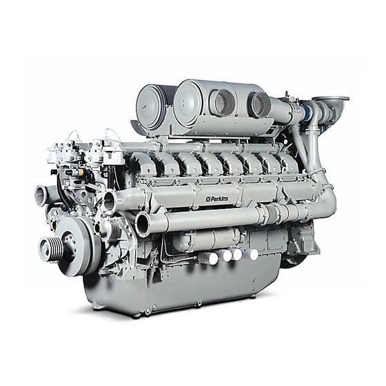
BRIEF DESCRIPTION OF THE 4012/16 GAS ENGINES 4012TESI 12 cylinder, ‘V’ form, 4 stroke, gas engine, water cooled, (MINNOX) turbo-charged, water cooled charge air cooler with separate water pump and cooling circuit, lean burn, low NOx emission levels, 9.5:1 compression ratio 4012TESI 12 cylinder, ‘V’... - Page 7 4012TESI (MINNOX) 4012TESI (MINNOX)
- Page 8 4016TESI (MINNOX) 4016TESI (MINNOX)
-
Page 9: General Information
GENERAL INFORMATION SAFETY Engine lift equipment Use only the lift equipment which is designed for the engine. Use lift equipment or obtain assistance to lift heavy engine components such as the cylinder block, cylinder head, flywheel housing, crankshaft and flywheel. Check the engine lift brackets for security before the engine is lifted. -
Page 10: California Proposition 65 Warning
GENERAL INFORMATION Environmental protection Practical Information To clean components There legislation protect environment from the incorrect disposal of It is important that the work area is kept clean used lubricating oil. To ensure that the and that the components are protected from environment is protected, consult your Local dirt and debris. -
Page 11: Gas Engine Data
GAS ENGINE DATA The figures quoted are based on engines set to meet the ISO 3046/1 1981 Condition. For full technical data please refer to the Product Information Manual. Type (Gas) 12 cylinder and 16 cylinder (MINNOX) 'V' form, water cooled, turbocharged, wet exhaust manifolds with separate raw water cooled charge air cooler. -
Page 12: Gas System
GAS ENGINE DATA GAS SYSTEM 4012TESI (MINNOX) 4016TESI (MINNOX) Approved gas British Natural Gas Lower calorific value 34.71 MJ/nm Carburettor mixing unit Deltec 200 - 11 Carburettor throttle body Deltec 100 - 11 Deltec 140 - 11 Gas control valve Deltec 36 mm dia. -
Page 13: Induction System
GAS ENGINE DATA INDUCTION SYSTEM 4012TESI (MINNOX) 4016TESI (MINNOX) Air cleaner Twin Type (paper element) S551A Max. air intake depression 543 mm H O (40 mm Hg) (L.C. engines) 406 mm H O (30 mm Hg) (H.C. engines) Air restriction Indicator setting 380 mm H Twin Garrett (4016TESI 140 H.C. -
Page 14: Gas Engine Data
GAS ENGINE DATA PROTECTION EQUIPMENT Before resetting protection equipment, it must be established whether special settings (for that individual engine) have been specified in the engine sales contract. This is particularly important with ALL high water temperature settings, and ALL Cogen applications. Standard settings for protection equipment are as follows: High air manifold pressure switch 172 kPa (25.1 lb/in... -
Page 15: Torque Settings
TORQUE SETTINGS IT IS ESSENTIAL THAT THE CORRECT LENGTH OF SCREW OR WARNING BOLT IS USED. INSUFFICIENT THREAD MAY RESULT IN THE THREAD BEING STRIPPED. WHEREAS TOO LONG A THREAD MAY RESULT IN BOTTOMING IN A BLIND HOLE, OR CATCHING ON ADJACENT COMPONENTS. NOTE: * Bolt and threads must be lubricated with clean engine oil. - Page 16 TORQUE SETTINGS Ibf.ft CAMSHAFT GROUP Camshaft gear bolt Camshaft thrust plate bolt Camshaft follower housing capscrew Cam follower housing bolt Idler gear hub bolts WATER PUMP AND OIL PUMP GROUPS Water pump/oil pump gear units Water header to oil cooler bolts Water header to gearcase bolts Raw water pump gear securing nut (non lubricated thread) Engine Feet...
- Page 17 TORQUE SETTINGS GENERAL TORQUE LOADINGS The following torque loadings are general for metric coarse threads for grade 8.8 steel and do not supersede the figures quoted above. Thread Size (mm) Ibf.ft M10-12.9 steel These are based to BS 3692. 4012/16 Gas, February 1998...
-
Page 18: Lubricating Oil
LUBRICATING OIL QUANTITY OF OIL 4012TESI 4016TESI The total system capacity 178 litres (39 gallons) 238 litres (52 gallons) The maximum sump capacity 159 litres (35 gallons) 214 litres (47 gallons) The minimum dipstick mark indicates 136 litres (30 gallons) 147 litres (32 gallons) CAUTION In order to select a suitable lubricating oil for a gas engine it is necessary to consider... - Page 19 LUBRICATING OIL The following should be regarded as critical parameters: Viscosity at 100°C 16.5 cSt maximum Insolubles 1.5 maximum Total Acid Number (TAN) less than 4 times the TAN value for new oil. Total Base Number (TBN) 50% less than new oil value. Total base number (TBN) and total acid number (TAN) must not cross over.
-
Page 20: Lubricating Oil
LUBRICATING OIL During the early life of the engine it will be found that the parameters marked * will have higher levels as a result of the running in procedure. UNDER NO CIRCUMSTANCES IS THE OIL TO BE USED FOR MORE THAN 900 HOURS EVEN IF THE ANALYSIS SHOWS THAT THE OIL IS IN ACCEPTABLE CONDITION. - Page 21 COOLANT When mixing the anti-freeze with the water ALWAYS STOP WARNING always follow manufacturer's THE ENGINE AND recommendation which is to add the anti- ALLOW THE PRESSURISED SYSTEM freeze to water and mix thoroughly before TO COOL BEFORE REMOVING THE adding the mixture to the engine cooling FILLER CAP.
-
Page 22: Gas Specification
GAS SPECIFICATION A new engine will be set to operate on clean natural gas conforming to the British natural gas specifications having a lower calorific value of 34.71 MJ/Sm³ (930 BTU/Sft³). The difference between high calorific value (HCV) and low calorific value (LCV) is that (HCV) is the total amount of heat given off by the gas during combustion and the (LCV) is the high calorific value less the amount of heat used to vaporize the water content of the gas. -
Page 23: Gas Specification
GAS SPECIFICATION DERATING IT IS ESSENTIAL WARNING THAT FULL ACCOUNT IS TAKEN OF ALL DERATING INFLUENCES WHETHER GAS SPECIFICATION, ALTITUDE, AMBIENT TEMPERATURE OR HUMIDITY. WHERE ANY OF THESE DEVIATE FROM THE STANDARD SPECIFIED IN THIS MANUAL THE RATING OF THE GAS ENGINE MUST BE ADJUSTED AS INSTRUCTED BELOW. -
Page 24: Operating Instructions
OPERATING INSTRUCTIONS PREPARATION FOR INITIAL START FILLING THE ENGINE WITH OIL Remove the drain plug to ensure sump is clean and empty, refit and tighten the plug. Remove the oil filler plug situated on the left hand side of the gearcase by rotating T-bar anti-clockwise and pulling Fig. -
Page 25: Batteries
OPERATING INSTRUCTIONS BATTERIES (PERKINS BATTERIES ARE SUPPLIED DRY CHARGED. SEE INSTALLATION MANUAL TSL4200) HAND PROTECTION WARNING MUST BE WORN WHEN CHECKING ELECTROLYTE LEVEL IN THE BATTERY. INFLAMMABLE GAS IS GIVEN OFF BY THE BATTERY. DO NOT CHECK WITH A NAKED FLAME. Fig. -
Page 26: Instrument Panel (Engine Mounted)
INSTRUMENT PANEL (ENGINE MOUNTED) DESCRIPTION The instrument panel is flexibly mounted on the side of the engine between the air manifold flanges. Some instruments are duplicated giving readings for A and B bank (see Fig. 5). Battery charging rate Coolant temperature 'A' bank Lubricating oil temperature 'A' bank Lubricating oil pressure 'A' bank Taco and hours run... - Page 27 INSTRUMENT PANEL Engine water temperature gauge (Fahrenheit/Centigrade) Fig. 6 The coolant temperature during normal operation should be between 65°C - 85°C (149°F - 185°F). If the temperature should rise above 93°C (200°F) for a prolonged period of time, stop the engine and investi- gate the cause.
-
Page 28: Exhaust Temperature Gauge (Optional)
INSTRUMENT PANEL Engine tachometer and hour counter (revolutions per minute x 1000 and hours) (see Fig. 10). The electrically operated tachometer/hour counter shows the speed of the engine in rev per min. and the actual operating hours the engine has run. The tachometer/hour counter starts operating from an alternator voltage of 12 V onwards, which has already been reached at engine idling speed. -
Page 29: Final Checks And Initial Startup
OPERATING INSTRUCTIONS 3. Starting (manual) FINAL CHECKS AND INITIAL STARTUP 3.1) Turn on gas at manual valve. Gas supply train must comply with British 3.2) Press start button/turn ignition gas Code IM17. See Fig. 1 page 16 in the key. Workshop Manual. - Page 30 OPERATING INSTRUCTIONS 4. Stopping 4.1) Remove load, run for 3 to 5 minutes to reduce combustion system temperatures localised boiling of coolant and to prevent oil carburizing in the turbocharger bearing housing. 4.2) Stop engine by de-energising solenoid valves governor. DO NOT press the stop button for normal...
-
Page 31: Gas Engine Start/Stop Sequence (Automatic)
OPERATING INSTRUCTIONS GAS ENGINE START/STOP SEQUENCE (AUTOMATIC) START SIGNAL ENGINE RECEIVED RUNNING IS GAS LOW GAS PRESSIRE PRESSURE ALARM & LOCKOUT WITHIN LIMITS? SWITCH OFF OVER SPEED IGNITION SYSTEM FAULT? & DE-ENGERGISE GAS VALVES ENERGISE GOVERNOR OTHER DE-ENERGISE ENGINE GAS VALVES FAULT? ENERGISE STARTER MOTOR &... -
Page 32: Maintenance Procedures
MAINTENANCE PROCEDURES Towards the rear of this section there is a check list sheet continuous duty generator sets which is to be used as a guide operators maintenance personnel. The following schedule details some of the maintenance to be carried out as in the maintenance check lists, however not all are detailed. - Page 33 MAINTENANCE PROCEDURES BATTERIES HAND PROTECTION WARNING MUST BE WORN WHEN CHECKING ELECTROLYTE LEVEL IN THE BATTERY. INFLAMMABLE GAS IS GIVEN OFF BY THE BATTERY. DO NOT CHECK WITH A NAKED FLAME. Remove the plugs or 'quick fill' covers and Fig. 16 check the level of electrolyte.
- Page 34 MAINTENANCE PROCEDURES TURBOCHARGERS If the engine has been overhauled and a filter joint fitted to the turbocharger oil feed, this should now be removed and replaced with the standard joint. See Service Bulletin 301 (Revised) and FOR ENGINES OPERATING ON BIOGAS, LANDFILL GAS, ETC.
- Page 35 MAINTENANCE PROCEDURES FAN BEARINGS AND BELTS To adjust slacken the jockey pulley pivot and adjuster bolts, and operate the jockey pulley lever. DISCONNECT WARNING Moving the jockey pulley lever outwards will BATTERIES OR ANY tension the belts and inwards will slacken OTHER MEANS OF STARTING.
- Page 36 MAINTENANCE PROCEDURES DISCONNECT WARNING BATTERIES OR ANY OTHER MEANS OF STARTING. WHEN USING COMPRESSED AIR OR CLEANING AGENTS ALWAYS WEAR EYE PROTECTION, AND PROTECTIVE GLOVES. CRANKCASE BREATHER (IMPROVED DESIGN) FITTED TO LATER ENGINES Fig. 19 The crankcase breather is mounted on the side of the thermostat housing Fig.
- Page 37 MAINTENANCE PROCEDURES DISCONNECT WARNING BATTERIES OR ANY OTHER MEANS OF STARTING. ALWAYS WEAR PROTECTIVE GLOVES. FOR EXTENDED OIL CHANGE PERIOD (WITH OIL ANALYSIS PROGRAMME) PAGES 14 - 16 ON ENGINES OPERATING ON BIO GAS AND OTHER GASES (NOT BRITISH NATURAL GAS) CLEANING THE CENTRIFUGAL LUBRICATING OIL FILTER Stop the engine, and allow time for...
- Page 38 MAINTENANCE PROCEDURES NOTE: It is suggested that oil analysis tests are carried out at regular intervals to check that these maintenance intervals satisfactory. CHANGING ENGINE OIL AND STANDARD SPIN-ON TYPE LUBRICATING OIL FILTERS DISCONNECT WARNING BATTERIES OR ANY OTHER MEANS OF STARTING. ALWAYS WEAR PROTECTIVE GLOVES.
- Page 39 MAINTENANCE PROCEDURES NOTE: If the flexible connections to the filter DISCONNECT WARNING are removed for any reason, it is essential BATTERIES OR ANY that they are reconnected correctly to avoid OTHER MEANS OF STARTING. ALWAYS unfiltered oil getting into the engine. WEAR PROTECTIVE GLOVES.
- Page 40 MAINTENANCE PROCEDURES NOTE: Prepare for a small spillage of oil REDUCE ENGINE WARNING from the filter as each canister is removed, SPEED TO IDLING IF by placing a container of about 5 litres or 1 CHANGING THE FILTERS WHILST gallon capacity under the filter. ENGINE IS RUNNING.
- Page 41 MAINTENANCE PROCEDURES DISCONNECT WARNING BATTERIES OR ANY OTHER MEANS OF STARTING THE ENGINE. CHANGING AIR FILTER (SEE SECTION A1 IN THE WORKSHOP MANUAL) STANDARD Remove the end cover (3) of the air filter housing, after unscrewing the retaining wing Fig. 25 nut, carefully lift out the paper air filter element (1).
- Page 42 MAINTENANCE PROCEDURES CLOSED CIRCUIT BREATHER The closed circuit breather separators (1) are mounted on each side of the gearcase and are connected to the carburettor mixer inlet via the breather valve (2). To clean the breather separator remove the complete unit from the engine (see Fig.
- Page 43 MAINTENANCE PROCEDURES EQUALISING BRIDGE PIECES AND SETTING VALVE CLEARANCES NOTE: The bridge pieces must be set before attempting to set the valve clearances. DISCONNECT WARNING BATTERIES OR ANY OTHER MEANS OF STARTING. Fig. 29 Remove the 4 screws (1) from the rocker cover (2), lift off the cover peel off and throw away the old gasket (3) Pull the spark plug lead tube (4) from the spark plug bush (see...
- Page 44 MAINTENANCE PROCEDURES EQUALISING THE BRIDGE PIECES DISCONNECT WARNING BATTERIES OR ANY OTHER MEANS OF STARTING THE ENGINE. Having rotated the engine to the correct position, check that the inlet and exhaust rockers have clearance before continuing with the next operation. Loosen the lock nut Fig.
- Page 45 MAINTENANCE PROCEDURES ENGINE 4016TESI SET BRIDGE PIECE VALVES ROCKING ON AND VALVE CLEARANCE CYLINDER NO. T.D.C. ON CYLINDER NO. A1 & A8 B1 & B8 A3 & A6 B3 & B6 A7 & A2 B7 & B2 A5 & A4 B5 &...
-
Page 46: Maintenance Procedures
MAINTENANCE PROCEDURES BRITISH NATURAL GAS, BIOGAS AND OTHER GASES CONTINUOUS DUTY CHECK LIST (BASED ON ENGINES RUNNING AT 1500 RPM NORMAL OPERATION AND STANDARD OIL CHANGE PERIOD) CONTINUOUS DUTY MAINTENANCE OPERATIONS TO BE PERFORMED SYSTEM OPERATION DESCRIPTION Lubricating Check For leaks and oil pressure •... - Page 47 MAINTENANCE PROCEDURES BRITISH NATURAL GAS CONTINUOUS DUTY CHECK LIST (BASED ON ENGINES RUNNING AT 1500 RPM NORMAL OPERATION AND EXTENDED OIL CHANGE PERIOD) CONTINUOUS DUTY MAINTENANCE OPERATIONS TO BE PERFORMED SYSTEM OPERATION DESCRIPTION Lubricating Check For leaks and oil pressure •...
- Page 48 MAINTENANCE PROCEDURES BIOGAS AND OTHER GASES (NOT BRITISH NATURAL GAS) CONTINUOUS DUTY CHECK LIST (BASED ON ENGINES RUNNING AT 1500 RPM NORMAL OPERATION AND EXTENDED OIL CHANGE PERIOD) CONTINUOUS DUTY MAINTENANCE OPERATIONS TO BE PERFORMED SYSTEM OPERATION DESCRIPTION • Lubricating Check For leaks and oil pressure •...
-
Page 49: Fault Tracing Chart
4012 & 4016 GAS ENGINES FAULT TRACING CHART Fig. 34 4012/16 Gas, February 1998... - Page 50 4012/16TESI (MINNOX) WIRING DIAGRAM WITH CAV STARTER AND PROTECTION SWITCHES (Fig. 35) Oil press switch 220Ω5w resistor Charging alternator Repeater relay Start motor ‘Start relay Engine fault switches left/right banks Water temp. Oil press 10. All fault switches close on a fault. One side of all fault switches are identical.
- Page 51 4012/16 (GAS) MINNOX ENGINE WIRING DIAGRAM STARTING CIRCUIT WITH BUTEC STARTERS AND OPTIONAL INSTRUMENT PANEL (Fig. 36) 1. Charging alternator 2. Ammeter 3. Oil press 4. Oil temp. 5. Water temp. 6. Tacho 7. Oil press 8. Oil temp. 9. Water temp. 10.
-
Page 52: Early 4012 Series Gas Ignition And Heinzmann Wiring System
EARLY 4012 SERIES GAS IGNITION AND HEINZMANN WIRING SYSTEM (Fig. 37) 1. DISN Unit 2. 19 Pin plug 3. 6 Pin plug 4. Pick-up 5. Engine fitted emergency stop button 6. H.T. Leads 7. Spark plugs 8. Ignition coils 9. Firing order 10. -
Page 53: Current 4012 Series Gas Ignition And Heinzmann Wiring System
CURRENT 4012 SERIES GAS IGNITION AND HEINZMANN WIRING SYSTEM (Fig. 38) 1. DISN Unit 2. 19 Pin plug 3. 6 Pin plug 4. Pick-up 5. Engine fitted emergency stop button 6. H.T. Leads 7. Spark plugs 8. Magnetic disc 9. Ignition coils 10. -
Page 54: 4012/16 (Gas) Minnox Engine Wiring Diagram Of Standard
4012/16 (GAS) MINNOX ENGINE WIRING DIAGRAM OF STANDARD PROTECTION PACK AND OPTIONAL BRITISH GAS COUNCIL PROTECTION EQUIPMENT 17. Gas solenoid valves not normally (Fig. 39) supplied by Perkins can be four off Standard fitted equipment depending on gas pipe work arrangement Magnetic pick-up 18. -
Page 55: Early 4016 Series Gas Ignition And Heinzmann Wiring System
EARLY 4016 SERIES GAS IGNITION AND HEINZMANN WIRING SYSTEM (Fig. 40) DISN Unit 19 Pin plug 6 Pin plug Pick-up Engine fitted emergency stop button H.T. Leads Spark plugs Ignition coils Firing order 10. Fused terminals 11. Heinzmann actuator 'A' bank left 12. -
Page 56: Current 4016 Series Gas Ignition And Heinzman Wiring System
CURRENT 4016 SERIES GAS IGNITION AND HEINZMAN WIRING SYSTEM (Fig. 41) 1. DISN Unit 2. 19 Pin plug 3. 6 Pin plug 4. Pick-up 5. Engine fitted emergency stop button 6. HT Leads 7. Spark plugs 8. Ignition Coils 9. Magnetic Disc 10. - Page 57 © 1998 Perkins Engines Company Limited All Rights Reserved...
Need help?
Do you have a question about the 4012TESI Series and is the answer not in the manual?
Questions and answers