
Related Manuals for Emerson Rosemount 2555


Summary of Contents for Emerson Rosemount 2555
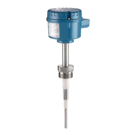
- Page 1 Quick Start Guide 00825-0100-2555, Rev AC October 2020 ™ Rosemount 2555 Solids Level Switches Capacitance Probe...
-
Page 2: Table Of Contents
Quick Start Guide October 2020 Contents Introduction..........................3 Mechanical installation.........................9 Electrical installation........................14 Configuration..........................20 Troubleshooting........................39 Maintenance..........................44 Quick Start Guide... -
Page 3: Introduction
Equipment service needs. • 1-800-654-7768 (24 hours a day — includes Canada) • Outside of these areas, contact your local Emerson representative. WARNING Physical access Unauthorized personnel may potentially cause significant damage to and/or misconfiguration of end users’ equipment. This could be intentional or unintentional and needs to be protected against. - Page 4 Equipment ratings and certifications are no longer valid on any products that have been damaged or modified without the prior written permission of Emerson. Any continued use of product that has been damaged or modified without the written authorization is at the customer’s sole risk and expense.
- Page 5 • For information on Rosemount nuclear-qualified products, contact your local Emerson Sales Representative. Individuals who handle products exposed to a hazardous substance can avoid injury if they are informed of and understand the hazard.
- Page 6 787 in. (20 m) with an extension rope. The use of a sliding sleeve is recommended so that the switching point can be changed easily during the live operation of the level switch. Note The Rosemount 2555 Product Data Sheet has all dimensional drawings. Quick Start Guide...
- Page 7 With active shield technology, the RF measurements are unaffected by product build-up on the probe. The inactive length is used to extend the overall probe length. Note See the Rosemount 2555 Product Data Sheet for extended length options. Quick Start Guide...
- Page 8 When the solids medium in the vessel (silo) rises and covers the rod, it causes an increase of capacitance that is detected by the electronics and the output switches to indicate a 'covered' state. The electrical output will vary depending on the electronics selected when the Rosemount 2555 was ordered. Quick Start Guide...
-
Page 9: Mechanical Installation
Ensure that the process connection is tightened by the correct amount of torque and sealed to prevent process leaks. 4. Technical data a. The Rosemount 2555 Product Data Sheet has all the technical specifications. See Emerson.com/Rosemount for other language versions. - Page 10 (see Emerson.com/Rosemount other language versions). 2.1.3 Tightening threaded process connections When tightening the threaded process connection of a Rosemount 2555: • Use an open-ended wrench on the hexagonal boss of the level switch or the sliding sleeve. • Never tighten by using the housing.
- Page 11 October 2020 Quick Start Guide 2.1.6 Orientation of cable glands When the level switch is mounted horizontally, ensure the cable glands are pointed downwards to avoid water getting inside the housing. Unused conduit entries must be completely sealed with a suitably rated stopping (blanking) plug.
- Page 12 Quick Start Guide October 2020 Mounting the level switch Figure 2-3 Figure 2-4 show how the Rosemount 2555 should be mounted. Figure 2-3: Correct and Incorrect Mounting (Rod Version) > 1.8 (50) A. Active probe B. Mounting the level switch at an angle helps solids material to fall away and prevent build-up C.
- Page 13 October 2020 Quick Start Guide Figure 2-4: Correct and Incorrect Mounting (Rope Version) > 1.8 (50) > 1.8 (50) A. Active probe B. Correct installation: The socket height is short C. Correct installation: The inactive length is correctly used within a long socket D.
-
Page 14: Electrical Installation
Before any electrical installation, connect the internal or external Potential Earth (PE) terminal to a grounding point at the installation site if the Rosemount 2555 is mounted to a non-metal silo or other storage vessel. Note Wiring the level switch for the location of the PE terminals. - Page 15 October 2020 Quick Start Guide 3.1.7 Wiring Field wiring cables The diameter has to match the clamping range of the used cable gland. The cross-section has to match the clamping range of the connection terminals and the maximum current must be considered. All field wiring must have insulation suitable for at least 250 Vac.
- Page 16 Quick Start Guide October 2020 Unused entries have to be closed with suitably rated stopping (blanking) plugs. Where available, the factory-provided parts must be used. The diameter of the field wiring cable must match the clamping range of the cable clamp. If factory-provided parts are not used, the following must be ensured: •...
- Page 17 Provide protection for relay contacts and output transistors to protect the device against inductive load surges. 3.1.12 Static charging The Rosemount 2555 must be grounded to avoid a static electrical build-up. This is particularly important for applications with pneumatic conveying and non-metallic containers.
- Page 18 Quick Start Guide October 2020 Figure 3-2: Connections Overview for Type 'D' Housing 1 1 2 3 4 5 6 7 8 A. Connection terminals B. Internal Protective Earth (PE) terminal Figure 3-3: Connections Overview for Type 'DE' Housing A. Connection terminals (in a terminal box for increased safety). The fixing torque is 0.5 to 0.6 Nm B.
- Page 19 October 2020 Quick Start Guide 3.2.1 Wiring the power supply and the DPDT relay Power supply • 21 to 230 Vac (50/60 Hz) ±10%, 1.5 VA • 21 to 230 Vdc ±10%, 1.5 W • Fuse on power supply: maximum 10 A, 250 V, HBC, fast or slow Signal output (floating relay DPDT) •...
-
Page 20: Configuration
Maintenance (flashing) or error (not flashing) Powering up the first time (calibration) Calibration automatically starts when the Rosemount 2555 is powered up for the first time. If the level switch is powered off and then on again, this calibration procedure is not repeated when starting up. - Page 21 Fail Safe High and Low, signal output delay, and sensitivity. Postrequisites The Rosemount 2555 is now calibrated and ready to be configured. Measurement mode The level switch indicates the actual measured capacitance and the status of the signal output.
- Page 22 Quick Start Guide October 2020 Quick-start menus Note The LED is flashing red while the quick-start menu is displayed. If no button is pressed within 5 minutes, the unit automatically returns to the measurement mode. All changed menu settings are saved. Table 4-2: In Measurement Mode When the level switch is in Measurement mode, press and hold the MENU button for 3 seconds to enter the quick-start menu.
- Page 23 October 2020 Quick Start Guide Table 4-3: Quick-start Menus (continued) Display Description Menu item Sensitivity Required capacitance increase between uncovered probe (after calibration) and switch to output covered probe Change the preset value only if required by the application. See Guide to push-button calibration.
- Page 24 Quick Start Guide October 2020 Guide to push-button calibration Push-button calibration needs to be done if Power up calibration at first time operation was not successful or the unit was changed to another location or a significant change of DK was present after changing the material.
- Page 25 October 2020 Quick Start Guide 4.5.1 Push-button calibration for an uncovered probe only Prerequisites • The level switch must be correctly mounted and wired. • The level of the solids material must be below the probe. Procedure 1. Review the stages in the calibration procedure. A.
- Page 26 2. Press and hold the CAL button again for three seconds to restart the calibration. If any other messages are displayed, see Maintenance and error messages. Postrequisites The Rosemount 2555 is now calibrated and ready to be configured. Quick Start Guide...
- Page 27 October 2020 Quick Start Guide 4.5.2 Push-button calibration for uncovered and covered probes Prerequisites • The level switch must be correctly mounted and wired. • The level of the solids material must be below the probe. Procedure 1. Review the stages in the calibration procedure. A.
- Page 28 Quick Start Guide October 2020 6. Set the sensitivity. Calculate the capacitance difference between the uncovered and covered probe. Set the sensitivity as follows (quick-start menu item D): Horizontal mounting Vertical mounting (rope version) Capacitance Sensitivity Capacitance Sensitivity 0.8 to 1.5 pF 0.5 pF 0.5 to 1.0 pF 0.5 pF...
- Page 29 Maintenance and error messages. Postrequisites The Rosemount 2555 is now calibrated and ready to be configured. Resetting the first power-up calibration An already calibrated level switch can be reset to perform a new power-up calibration. This may be needed if installing it in a different silo or if it has to be pre-configured before being shipped.
- Page 30 Maintenance and error messages. Postrequisites The Rosemount 2555 is now calibrated and ready to be configured. Advanced menu Note The LED will be red and flashing while the menu is displayed. If no button is pressed within 5 minutes, the unit automatically returns to the measurement mode.
- Page 31 October 2020 Quick Start Guide Table 4-5: Auto Recalibration Menu (Advanced Menu) Display Description Menu item Auto recalibration to uncovered probe. It is possible to commission an already filled silo (covered probe). A proper calibration is not possible with covered probe. A solution is to do an auto calibration as soon as the silo becomes empty (uncovered probe).
- Page 32 Quick Start Guide October 2020 Table 4-6: Manual calibration menu (Advanced menu) (continued) Display Description Menu item Sensitivity range. Low sensitivity range allows to detect a High capacitance change of ≥ 2 pF. High sensitivity range allows to detect a capacitance change of ≥...
- Page 33 See Troubleshooting. Minimum Stored Electronics Temperature °C Maximum Stored Electronics Temperature °C Software version Service data This manufacturer data is for the use of Emerson and not covered in this manual. Factory default setting. Quick Start Guide...
- Page 34 The locking code can be any number from 1 to 9999. A locking code of disables the password protection. Contact Emerson if a locking code was set but has been forgotten. Factory reset. This resets all user-entered data to the factory defaults. The level switch automatically starts a calibration.
- Page 35 October 2020 Quick Start Guide The DK values are required only to be roughly known, so as to set the sensitivity range. For the calibration procedure, see Powering up the first time (calibration). Table 4-9: Manual Calibration Guide Sensitivity Calibration: Increase to Calibration: range...
- Page 36 If the actual measured capacitance is close to the limits of what the electronic can measure (400 pF with sensitivity setting Low or 100 pF with sensitivity setting High). See Maintenance and error messages. Postrequisites The Rosemount 2555 is now calibrated and ready to be used. Quick Start Guide...
- Page 37 October 2020 Quick Start Guide 4.10.2 Manual calibration for uncovered and covered probes Prerequisites • The level switch must be correctly mounted and wired. • The level of the solids material must be below the probe. Manual calibration must be set to ON (Advanced menu, item K) •...
- Page 38 If the actual measured capacitance is close to the limits of what the electronic can measure (400 pF with sensitivity setting Low or 100 pF with sensitivity setting High). See Maintenance and error messages. Postrequisites The Rosemount 2555 is now calibrated and ready to be configured. Quick Start Guide...
-
Page 39: Troubleshooting
October 2020 Quick Start Guide Troubleshooting Maintenance and error messages The level switch indicates error messages while in measurement mode and during calibration routines. Table 5-1: In Measurement Mode Display Description Possible causes and solutions Flashing red Under Range Probe is defective or the probe is Actual measured incorrectly wired. - Page 40 Quick Start Guide October 2020 Table 5-2: During Power-up or Push-button Calibration Display Description Possible causes and solutions Flashing red Under Range Probe is defective or the probe is Actual measured incorrectly wired. capacitance is lower than 3 pF. The signal output relay is de-energized.
- Page 41 October 2020 Quick Start Guide Table 5-3: During Manual Calibration Display Description Possible causes and solutions Yellow or green With the sensitivity A long rope version in range set to high. an empty silo may exceed 100 pF Actual measured capacitance.
- Page 42 Quick Start Guide October 2020 General items Table 5-4: General Items Situation Behavior of the Possible reason Possible solution electronic Signal output state The actual The level switch is Recalibrate. is 'probe covered' measured not properly even though the capacitance calibrated.
- Page 43 October 2020 Quick Start Guide Check the probe wiring Prerequisites The power supply to the level switch must be switched off. Procedure 1. Clean away any deposits on the probe. Take out the electronic board and disconnect internal wires. Check the orange, yellow, and green/yellow wires with a multimeter.
-
Page 44: Maintenance
An accumulation of dust on the housing does not increase the surface temperature. However, dust can be safely removed with a damp cloth. Never use a dry cloth because it may cause an electrostatic discharge. See the Rosemount 2555 Product Certifications document for the maximum surface temperatures in hazardous area (classified locations) applications. - Page 45 October 2020 Quick Start Guide Production date The production year is shown on the nameplate. Spare parts Refer to the Rosemount 2555 Product Data Sheet for all spare parts. Quick Start Guide...
- Page 46 Quick Start Guide October 2020 Quick Start Guide...
- Page 47 October 2020 Quick Start Guide Quick Start Guide...
- Page 48 The Emerson logo is a Twitter.com/Rosemount_News trademark and service mark of Emerson Electric Facebook.com/Rosemount Co. Rosemount is a mark of one of the Emerson Youtube.com/user/ family of companies. All other marks are the RosemountMeasurement property of their respective owners.
Need help?
Do you have a question about the Rosemount 2555 and is the answer not in the manual?
Questions and answers