Table of Contents
Advertisement
Quick Links
ELECTRIC 60-INCH WINGSPAN
I N S T RU C T I O N M A N UA L
E n t i r e c o n t e n t s C o p y r i g h t 2 0 1 4 M a x f o r d U S A
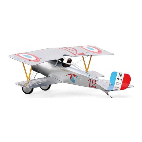
Con grat u lat i on s on you r p u rch a se of M axfo rd US A' s scal e WWI Ni eu p ort 17
We invite you to enjoy the pride of ownership and the joy of flyin g this high
quality balsa, composite, and light-ply Almost-Ready-to-Fly aircraft.
History of the Nieuport 17 ............ .........................2
Important safety precautions .................................. 2
Warranty, liability waiver, and return policy ......... 4
Special features of this Nieuport 17 ARF .............. 5
Specifications ......................................................... 5
NEUPORT 17
TABLE OF CONTENTS
Page 1 of 18
Parts List ............................................................ 5
Assembly instructions ...................................... 6
Setup and adjustments .................................... 16
Preflight checks ............................................. 17
!
Advertisement
Table of Contents

Related Manuals for Maxford USA WWI NEUPORT 17


Summary of Contents for Maxford USA WWI NEUPORT 17
-
Page 1: Table Of Contents
ELECTRIC 60-INCH WINGSPAN NEUPORT 17 I N S T RU C T I O N M A N UA L E n t i r e c o n t e n t s C o p y r i g h t 2 0 1 4 M a x f o r d U S A Con grat u lat i on s on you r p u rch a se of M axfo rd US A’... -
Page 2: History Of The Nieuport 17
Boyau, Armand Pinsard, Réné Dorne, Gabriel Guerin, Alfred Duellin and Jean Navarre. The type was also used by American volunteers of the Escadrille Lafayette when they replaced their earlier Nieuports. The Maxford USA version of the Nieuport-17 has a 60” wingspan which is roughly 1/5 scale. The color scheme of this model is a replica of Réné... -
Page 3: Important Safety Precautions
5. If you are not an experienced R/C pilot or have not flown this type of model before, we recommend that you get the assistance of an experienced R/C pilot. 6. Throughout the lifetime of this model, use only the Maxford USA-recommended or same- sized engine or equivalent electric power system and a new or well-maintained R/C radio system and batteries recommended by the maker of the engine (or motor) and radio system. -
Page 4: Warranty, Liability Waiver, And Return Policy
Maxford USA from all current or future liability for any personal injury, property damage, or wrongful death, and if you (the buyer or user of this product) are involved in any claim or suit, you will not sue Maxford USA or any of its representatives. -
Page 5: Special Features Of This Nieuport 17 Arf
SPECIAL FEATURES OF THIS NIEUPORT 17 Fits full assembled in most vehicles. All assemblies are precovered and required openings are predrilled and/or precut. The cowl and wheels are prefinished. Each aileron is separately operated by its own servo. ... -
Page 6: Assembly Instructions
Open the box and look over the parts. Check everything against the parts list and make sure everything is there and undamaged. If anything is missing or broken, contact Maxford USA at the address given on the last page of this manual within 10 days of receipt of the kit Mark the top of the sliding motor mount box to make sure that you don't later put it in upside down. - Page 7 APPLY THE MARKINGS: Trim off the flange on the front bottom of the headrest, then use thick CA or contact cement to glue it in place. Carefully trim the decals (stickers) and apply them as shown. Use dish washing soap and water on the larger stickers to allow a little movement before they stick permanently.
- Page 8 ASSEMBLE THE WINGS: Remove the aileron hatches from the bottom of the upper wing panels and install a sub-micro servo on the back of each hatch using the hardware that came with your servos. Attach an 18 inch extension to the servo wire and secure the connection by tying, taping, or shrink tube so that it won't come apart.
- Page 9 Locate the two metal interplane struts and four flying wire brackets. Mount the struts and brackets to the wingtip side of the wooden tabs that protrude from the bottom of the upper wings using the M3x12 machine screws and M3 locknuts provided. Locate the fiberglass wing joiner tubes for the upper and lower wings.
- Page 10 Remove the cowl and the sliding motor mount box. Mount your motor onto the box using the M3x20 socket head machine screws and M3 blind nuts provided. Carefully measure back 3 3/4" from the rear of the propeller and put a mark on the side of the box. Slip the box into the fuselage but DO NOT GLUE IT IN YET.
- Page 11 ASSEMBLE THE PULL- PULL CABLES AND FLYING WIRES: Assemble the clevis/cable connector assemblies. Put the clevis near the end of the cable adaptor so that there is at least 1/4" of thread left behind the clevis. Temporarily tighten the locking nut. Install a clevis/cable end assembly onto ONE end of each of the wire cables provided.
- Page 12 Pay careful attention to the way the elevator cables are routed. One continuous cable goes from the control horn on the top of one elevator, through the fuselage, through a crimp tube, and through that same side of the servo arm, then back out through the crimp tube, through the other side of the fuselage and to the control horn on the top of the other elevator.
- Page 13 INSTALL THE RUDDER PULL - PULL CABLES: Attach the rudder to the fuselage with two CA hinges using the same procedure as you used for the ailerons and elevators. Locate the two shortest cables and connect the clevis of one to the control horn on one side of the rudder.
- Page 14 Put one of the supplied wheel collars on each side of the axle, followed by the wheel, followed by another wheel collar. Locate the predrilled holes and install the two flying wire brackets near the landing gear struts on each side of the fuselage using the M3x16 self-tapping screws provided Install the tailskid wire in the...
- Page 15 and then to the top of the front cabane strut. Attach a clevis/cable adapter assembly to this end as well so that the wings will be removable. Don't forget to crimp and glue the tube at the bottom of the interplane strut also. (Optional pilot shown) Using the shorter cables, make up the two remaining flying wires for each wing.
-
Page 16: Setup And Adjustments
Carefully adjust the clevises to tighten the flying wires. They should all be tight enough to maintain a little tension, but not much. Tighten them evenly so that you do not create a warp in the top wing. The cables will stretch a little after a flight or two so you will have to retighten them later, but probably only once o r twice. -
Page 17: Preflight Checks
If you wish, you can install the pre- covered and folded black cockpit floor and the optional pilot. Slip the floor into the cockpit with the wider side toward the front. Carefully work it around so that it lies flat on top of the side frames. - Page 18 Your safety depends on how you use and fly it. Any testing or flying of this model airplane is done entirely at your own risk. We thank you for choosing Maxford USA and we sincerely wish you many happy landings! Manufactured by: Maxford USA RC Model Mfg, Inc.
Need help?
Do you have a question about the WWI NEUPORT 17 and is the answer not in the manual?
Questions and answers