
Subscribe to Our Youtube Channel
Related Manuals for National Instruments NI PXIe-5450


Summary of Contents for National Instruments NI PXIe-5450
- Page 1 NI PXIe-5450 User Manual National Instruments 400 MS/s, 16-bit differential I/Q generator for the PXI Express platform July 2008 372622A-01...
- Page 2 Thailand 662 278 6777, Turkey 90 212 279 3031, United Kingdom 44 (0) 1635 523545 For further support information, refer to the Technical Support and Professional Services appendix. To comment on National Instruments documentation, refer to the National Instruments Web site at and enter ni.com/info the info code feedback ©...
- Page 3 Instruments Corporation. National Instruments respects the intellectual property of others, and we ask our users to do the same. NI software is protected by copyright and other intellectual property laws. Where NI software may be used to reproduce software or other materials belonging to others, you may use NI software only to reproduce materials that you may reproduce in accordance with the terms of any applicable license or other legal restriction.
- Page 4 These classes are known as Class A (for use in industrial-commercial locations only) or Class B (for use in residential or commercial locations). All National Instruments (NI) products are FCC Class A products. Depending on where it is operated, this Class A product could be subject to restrictions in the FCC rules. (In Canada, the Department of Communications (DOC), of Industry Canada, regulates wireless interference in much the same way.) Digital...
-
Page 5: Table Of Contents
Waveform Amplitude Control ............2-15 Output Paths and Amplifiers ..........2-15 Attenuation .................2-16 Analog Gain Settings............2-16 Digital Gain ................2-17 Flatness Correction .............2-17 Filtering Effects.................2-17 Output Enable ...................2-18 Multichannel Configuration ................2-19 Configuring Channels for OSP ............2-19 © National Instruments Corporation NI PXIe-5450 User Manual... - Page 6 External Sample Clock Timebase ........2-41 Exporting Clocks ................2-42 Sample Clock ..............2-42 Sample Clock Timebase............. 2-43 Reference Clock ..............2-43 Destination Options............2-43 Onboard Memory .................... 2-44 Onboard Memory for Multichannel Waveform Generation..............2-46 NI PXIe-5450 User Manual viii ni.com...
- Page 7 Software Trigger ................2-74 Trigger Sources ....................2-74 Trigger Modes ....................2-75 Single Trigger Mode .................2-76 Continuous Trigger Mode..............2-77 Stepped Trigger Mode ..............2-78 Burst Trigger Mode................2-79 Trigger Timing ....................2-80 Filtering Effects ....................2-80 Data Mask ........................2-81 © National Instruments Corporation NI PXIe-5450 User Manual...
- Page 8 Creating an Application with LabVIEW .......... 4-5 NI-FGEN Example Programs for LabVIEW ..... 4-5 Considerations for using the LabVIEW Real-Time Module ............4-6 Creating an Application with LabWindows/CVI ......4-7 NI-FGEN Example Programs for LabWindows/CVI ..4-7 NI PXIe-5450 User Manual ni.com...
- Page 9 Creating a Marker Event in Arbitrary Sequence Mode ....4-27 Creating a Marker Event in Script Mode ..........4-27 Creating a Data Marker Event.................4-28 Configuring an Application for Streaming............4-29 Configuring Your Application for Direct DMA .......4-31 Simulation Mode .....................4-32 © National Instruments Corporation NI PXIe-5450 User Manual...
- Page 10 Resistive Matching ................5-9 Output Attenuation ......................5-10 Phase-Locked Looping....................5-11 Frequency Domain Fundamentals................. 5-12 SFDR....................... 5-12 THD ........................ 5-12 SINAD ......................5-13 ENOB......................5-13 Filtering and Interpolation..................... 5-13 Appendix A Technical Support and Professional Services NI PXIe-5450 User Manual ni.com...
-
Page 11: About This Manual
Italic text denotes variables, emphasis, a cross-reference, or an introduction to a key concept. Italic text also denotes text that is a placeholder for a word or value that you must supply. © National Instruments Corporation xiii NI PXIe-5450 User Manual... -
Page 12: Related Documentation
NI signal generators • NI Signal Generators Help—includes detailed information about the NI 5450 and the NI-FGEN VIs and functions • NI 5450 Specifications—provides the published specification values for the NI 5450 NI PXIe-5450 User Manual ni.com... -
Page 13: Features Supported On Smc Devices
Arbitrary Arbitrary Arbitrary Arbitrary Arbitrary List List Waveform, Waveform, Waveform, Waveform, Waveform, Sequence, Arbitrary Arbitrary Arbitrary Arbitrary Arbitrary Script Sequence Sequence, Sequence, Sequence, Sequence, Script Script Script, Script, Frequency Frequency List List © National Instruments Corporation NI PXIe-5450 User Manual... - Page 14 — Cycle 80% for 80% for square, 50% square, 50% for all other for all other User- 16,384 16,384 Variable Variable Variable 16,384 32,768 — † † † Defined samples samples samples samples Waveform Size NI PXIe-5450 User Manual ni.com...
- Page 15 32 complex 32 complex 32 complex 32 complex 32 complex samples samples samples samples samples samples Waveform — — 4 samples 4 samples 4 samples 4 samples 1 sample 2 samples Quantum © National Instruments Corporation NI PXIe-5450 User Manual...
- Page 16 † † † † † Length Maximum — — 16,777,215 16,777,215 16,777,215 16,777,215 16,777,215 16,777,215 Loop Count Maximum — — 2,097,151 2,097,151 2,097,151 2,097,151 2,097,151 2,097,151 † † † † † † Number of Sequences NI PXIe-5450 User Manual ni.com...
- Page 17 50 Ω, 75 Ω 50 Ω, 75 Ω 50 Ω, 75 Ω 50 Ω, 75 Ω 50 Ω, 75 Ω 50 Ω, 75 Ω 50 Ω, 75 Ω 50 Ω Output Impedance © National Instruments Corporation NI PXIe-5450 User Manual...
- Page 18 — Filter (automatic (automatic (maximum (maximum (maximum (maximum Interpo- for Standard for Standard lation Function Function 400 MS/s) 400 MS/s) 400 MS/s) 400 MS/s) Factor Frequency Frequency automatic automatic automatic automatic List modes) List modes) NI PXIe-5450 User Manual ni.com...
- Page 19 Using Using Using Using Using Using Device NI-TClk NI-TClk NI-TClk NI-TClk NI-TClk NI-TClk NI-TClk NI-TClk Synchroni- except for except for except for zation Standard Standard Standard Function Function Function mode mode mode © National Instruments Corporation NI PXIe-5450 User Manual...
- Page 20 Sample Sample Sample clock: clock: clock: clock: clock: 10 S/s to 10 S/s to 10 S/s to 10 S/s to 10 MS/s, 105 MS/s 105 MS/s 105 MS/s 105 MS/s 20 MS/s to 400 MS/s NI PXIe-5450 User Manual ni.com...
- Page 21 Divide- Divide- Divide- Divide- Divide- High- (Arbitrary Down, Down, Down, Down, Down, Resolution, Waveform High- High- High- High- High- Automatic Generation Resolution, Resolution, Resolution, Resolution, Resolution, Mode) Automatic Automatic Automatic Automatic Automatic © National Instruments Corporation NI PXIe-5450 User Manual...
- Page 22 ExtCalCon ExtCalCon ExtCalCon ExtCalCon ExtCalCon ExtCalCon stants stants stants stants stants stants stants stants Calibration niFgen_ niFgen_ niFgen_ niFgen_ niFgen_ niFgen_ niFgen_ niFgen_ Utility functions functions functions functions functions functions functions functions Functions ‡ NI PXIe-5450 User Manual 1-10 ni.com...
- Page 23 Refer to the device specifications for conditions. ‡‡ The minimum frequency available on these devices depends on the memory size of the device, as well as the value of the NIFGEN_ATTR_FUNC_MAX_BUFFER_SIZE attribute. © National Instruments Corporation 1-11 NI PXIe-5450 User Manual...
-
Page 24: Ni 5450 Overview
2 bidirectional PFI lines for importing triggers and exporting events • PXI trigger lines All NI 5450 devices follow industry-standard Plug and Play specifications for the PXI Express bus and offer seamless integration with compliant systems. © National Instruments Corporation NI PXIe-5450 User Manual... -
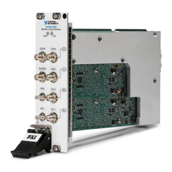
Page 25: Front Panel
Chapter 2 NI 5450 Overview Front Panel The following figure shows the NI PXIe-5450 front panel. This front panel has two SMB connectors and six SMA connectors. NI PXIe-5450 User Manual ni.com... - Page 26 The CH 0−/I− SMA connector provides complementary differential waveform output for channel 0. The CH 1+/Q+ SMA connector provides differential waveform output for channel 1. The CH 1−/Q− SMA connector provides complementary differential waveform output for channel 0. © National Instruments Corporation NI PXIe-5450 User Manual...
-
Page 27: Differential Channel Connectors
Set the amplitude of the generated output signal in terms of peak voltage by setting the gain value. NI-FGEN calculates and sets the correct amount of attenuation required for the desired gain value. Configure the output signal NI PXIe-5450 User Manual ni.com... -
Page 28: Load Impedance Compensation
The CLK IN connector can accept a Reference clock from an external source and phase-lock the internal clock of the signal generator to this external Reference clock. Refer to the device specifications for the allowable Reference clock frequencies and signal characteristics. © National Instruments Corporation NI PXIe-5450 User Manual... -
Page 29: External Sample Clock Input
Configure the Sample clock timebase source with the Sample Clock Timebase Source and Sample Clock Timebase Rate properties or the NIFGEN_ATTR_SAMPLE_CLOCK_TIMEBASE_SOURCE attributes. The device NIFGEN_ATTR_SAMPLE_CLOCK_TIMEBASE_RATE uses the internal sample clock timebase by default. NI PXIe-5450 User Manual ni.com... -
Page 30: Clk Out Connector
Sample clock timebase (with /M where M is an integer used to divide the Sample clock timebase frequency) • Script trigger Refer to the device specifications for information about acceptable input signal characteristics for the PFI lines and output signal characteristics. © National Instruments Corporation NI PXIe-5450 User Manual... -
Page 31: Access And Active Leds
The device has detected an error. NI-FGEN must access the device to determine the cause of the error. The LED remains red until the error condition is removed. Errors might include unlocked PLLs or an over-temperature condition. NI PXIe-5450 User Manual ni.com... -
Page 32: Power-Up And Reset Conditions
The sample rate is set to the maximum rate, with the Sample clock source set to the internal Sample clock timebase. • The Sample clock timebase is tuned by the internal reference control voltage. © National Instruments Corporation NI PXIe-5450 User Manual... -
Page 33: Thermal Shutdown
Review the guidelines in the Maintain Forced-Air Cooling Note to Users document that shipped with the product and make any necessary adjustments to ensure that the signal generator cools effectively. The thermal shutdown error continues to be reported until the device is successfully reset. NI PXIe-5450 User Manual 2-10 ni.com... -
Page 34: Theory Of Operation
The waveform data is sent from the DAC to the Analog Output path where the waveform data is filtered. • The Routing Matrix allows flexible routing of the PXI Trigger lines and the external PFI lines. © National Instruments Corporation 2-11 NI PXIe-5450 User Manual... -
Page 35: Hardware State Diagram
If the computer has just been powered on, reset, or the niFgen Reset Device VI or the niFgen_ResetDevice function has just been called, the device is in the default hardware state. NI PXIe-5450 User Manual 2-12 ni.com... - Page 36 The signal generator may still be generating and may be unpredictable at this point. When the driver software checks the status of the device, an error is returned. © National Instruments Corporation 2-13 NI PXIe-5450 User Manual...
-
Page 37: Analog Output
When the relay is enabled, the analog waveform is seen at the CH 0 +/− connector. Enable or disable the output of the analog waveform generator by using the NI PXIe-5450 User Manual 2-14 ni.com... -
Page 38: Waveform Amplitude Control
There are no programmable amplifiers and there is no method for adding DC offset to the waveform. The Direct path can generate a maximum of 1.0 V at the pk-pk © National Instruments Corporation 2-15 NI PXIe-5450 User Manual... -
Page 39: Attenuation
Note Digital gain is applied to the digital data before the data is passed to the DAC. Because relays are not used, digital gain allows glitch-free gain control at the expense of dynamic range. NI PXIe-5450 User Manual 2-16 ni.com... -
Page 40: Digital Gain
Enabling the onboard signal processing block can also introduce delay. Note The digital filter for the signal generator is inside the FPGA, before the Analog Output path. © National Instruments Corporation 2-17 NI PXIe-5450 User Manual... -
Page 41: Output Enable
The signal generator uses mechanical relays to switch between the output enable Note states. When you change a setting that causes a relay to switch, electromechanical relay bouncing interrupts the output signal for up to 10 ms. NI PXIe-5450 User Manual 2-18 ni.com... -
Page 42: Multichannel Configuration
Writing Data On the NI 5450, data can either be written to channel 0 and 1 independently, to I and Q independently, or to both channels simultaneously. © National Instruments Corporation 2-19 NI PXIe-5450 User Manual... -
Page 43: Interleaved Waveform Data
Therefore, the allocation size of interleaved data, in bytes, is equal to (number of channels being used) (the number of samples on each channel) × × Channel 0—Sample 1 Channel 1—Sample 1 Channel 0—Sample 2 Channel 1—Sample 2 Channel 0—Sample N Channel 1—Sample N NI PXIe-5450 User Manual 2-20 ni.com... -
Page 44: Onboard Signal Processing (Osp)
Pulse Shaping Gain & Offset Control and Interpolation The OSP block includes the following components: • Prefilter Gain and Prefilter Offset • FIR filters • Filtering and Interpolation • Writing I/Q Data © National Instruments Corporation 2-21 NI PXIe-5450 User Manual... -
Page 45: I/Q Rate
Prefilter offset can add offset to the I and Q stream during signal generation. Change the I and Q prefilter offsets independently by setting the Pre-Filter Offset I and Pre-Filter Offset Q properties or the NIFGEN_ATTR_OSP_PRE_FILTER_OFFSET_I attributes. The offset can NIFGEN_ATTR_OSP_PRE_FILTER_OFFSET_Q NI PXIe-5450 User Manual 2-22 ni.com... -
Page 46: Fir Filter Types
You can choose to ignore overflow errors caused by transients present in your data with the OSP Overflow Error Reporting property or the attribute. NIFGEN_ATTR_OSP_OVERFLOW_ERROR_REPORTING © National Instruments Corporation 2-23 NI PXIe-5450 User Manual... -
Page 47: Fir Filter Type: Flat
0.4. The frequency axis is scaled as a fraction of the I/Q Rate. – – – –10 – –20 – –30 – –40 – –50 –60 – – –70 –80 – –90 – – –100 Frequency (Hz) NI PXIe-5450 User Manual 2-24 ni.com... -
Page 48: Fir Filter Type: Raised Cosine
α of 0.5. The frequency axis is scaled as a fraction of the I/Q Rate. – –10 – – –20 – –30 –40 – – –50 –60 – – –70 –80 – – –90 –100 – Frequency © National Instruments Corporation 2-25 NI PXIe-5450 User Manual... -
Page 49: Fir Filter Type: Root Raised Cosine
α of 0.5. The frequency axis is scaled as a fraction of the I/Q Rate. – –10 – – –20 –30 – –40 – –50 – –60 – – –70 – –80 – –90 –100 – Frequency NI PXIe-5450 User Manual 2-26 ni.com... -
Page 50: Filtering And Interpolation
NIFGEN_ATTR_OSP_MODE specifies the generation mode implemented by the OSP block. The OSP block can operate in IF and Baseband modes. On the NI 5450, the default OSP mode is Baseband generation. © National Instruments Corporation 2-27 NI PXIe-5450 User Manual... -
Page 51: Osp Enabled
OSP block. When the onboard signal processing is enabled by setting the OSP Enabled Note property or the attribute, you cannot set the Sample Rate NIFGEN_ATTR_OSP_ENABLED property or the attribute. NIFGEN_ATTR_ARB_SAMPLE_RATE NI PXIe-5450 User Manual 2-28 ni.com... -
Page 52: Frequency Shift
When the NI 5450 is configured for single-channel operation in Real data processing Note mode, you can use the active baseband channel as a direct, frequency-shifted output, in addition to creating RF frequency shifts with an I/Q modulator. © National Instruments Corporation 2-29 NI PXIe-5450 User Manual... -
Page 53: Fir Filter Type
The following figure shows the behavior of the OSP block during arbitrary waveform generation. Digital Waveform Output Memory Engine Gain Onboard Signal Processing For normal arbitrary waveform generation, disable onboard signal processing by setting the OSP Enabled property or the attribute. NIFGEN_ATTR_OSP_ENABLED NI PXIe-5450 User Manual 2-30 ni.com... -
Page 54: Baseband Interpolation
Set the FIR Filter Type property or the attribute. NIFGEN_ATTR_OSP_FIR_FILTER_TYPE Set the corresponding filter parameter. Disable the carrier by setting the Carrier Enabled property or the attribute. NIFGEN_ATTR_OSP_CARRIER_ENABLED Download the low sample rate waveform(s) to the signal generator. © National Instruments Corporation 2-31 NI PXIe-5450 User Manual... -
Page 55: Baseband I/Q Interpolation
(Optional) Shift the frequency by calling the Frequency Shift property or the attribute. NIFGEN_ATTR_OSP_FREQUENCY_SHIFT Download the low sample rate waveform(s) to the signal generator. Read the sample rate by calling the Sample Rate property or the attribute. NIFGEN_ATTR_ARB_SAMPLE_RATE NI PXIe-5450 User Manual 2-32 ni.com... -
Page 56: Baseband Interpolation Considerations
Sample Rate property or the attribute. NIFGEN_ATTR_ARB_SAMPLE_RATE For optimum performance, National Instruments recommends maintaining the Note sample rate between 270 MS/s and 400 MS/s due to the fixed frequency characteristics of the image rejection filter. For more information about the image rejection filter, refer to the NI 5450 specifications. - Page 57 † Calculated from sinc response and typical filter rejection for the NI 5450. Refer to the NI 5450 specifications for more information about the expected performance of the NI 5450. NI PXIe-5450 User Manual 2-34 ni.com...
-
Page 58: Clock Source And Frequency
Sample clock timebase matches that of the PLL Reference clock when the two are phase-locked. Phase-locking also synchronizes multiple device clocks that are phase–locked to the same Reference clock. © National Instruments Corporation 2-35 NI PXIe-5450 User Manual... - Page 59 , and . The NIFGEN_ATTR_CLOCK_MODE NIFGEN_ATTR_REFERENCE_CLOCK_SOURCE values in the columns represent the values that can be set on these properties or attributes. Settings that line up horizontally show valid combinations of the NI-FGEN settings. NI PXIe-5450 User Manual 2-36 ni.com...
-
Page 60: Internal Sample Clock
Note Refer to the device specifications for information about the PLL reference frequencies available on your device. © National Instruments Corporation 2-37 NI PXIe-5450 User Manual... - Page 61 CLK IN front panel connector. PXI devices can also phase–lock to a 10 MHz Reference clock signal provided by the PXI bus (PXI_CLK10). Note Refer to the device specifications for information about available signal levels on the CLK IN front panel connector. NI PXIe-5450 User Manual 2-38 ni.com...
-
Page 62: External Sample Clock Sources
Set Sample Rate VI or the function. niFgen_ConfigureSampleRate Refer to the device specifications for the allowable voltages, signal types, and Note clocks that you can use for all external Sample clocks. © National Instruments Corporation 2-39 NI PXIe-5450 User Manual... -
Page 63: External Sample Clock Considerations
When configuring an external Sample clock, you can set the sample rate to the exact frequency you are using to avoid data errors by calling the niFgen Set Sample Rate VI or the function. niFgen_ConfigureSampleRate NI PXIe-5450 User Manual 2-40 ni.com... -
Page 64: External Sample Clock Timebase
Sample Clock Timebase Export Output Terminal property or the NIFGEN_ATTR_EXPORTED_SAMPLE_CLOCK_TIMEBASE_OUTPUT_ attribute. TERMINAL Refer to the device specifications for the allowable voltages, signal types, and Note clocks that you can use for an external Sample clock timebase. © National Instruments Corporation 2-41 NI PXIe-5450 User Manual... -
Page 65: Exporting Clocks
The Sample clock can be routed to the CLK OUT front panel SMA connector. Additionally, the exported clock can be divided down by an integer value (no less than 2) before being exported to the PFI <0..1> connectors, the NI PXIe-5450 User Manual 2-42 ni.com... -
Page 66: Sample Clock Timebase
Reference clock can be exported to the CLK OUT SMA connectors on the front panel to synchronize external devices. You must configure the device to export the desired clock to the CLK OUT SMA connector. © National Instruments Corporation 2-43 NI PXIe-5450 User Manual... -
Page 67: Onboard Memory
Sequence Sequence Sequence Waveform Waveform Waveform Free • • • Instructions Instructions • • • Instructions Memory NI PXIe-5450 User Manual 2-44 ni.com... - Page 68 Waveform Number of Loops Marker Placement –1 18,045 10,000 64,000 64,000 ..10,000 Sequence m: Stepped Trigger Mode Sequence Segment Waveform Number of Loops Marker Placement –1 10,000 64,000 20,000 1,000,000 © National Instruments Corporation 2-45 NI PXIe-5450 User Manual...
-
Page 69: Onboard Memory For Multichannel Waveform Generation
128 bytes. The following figure represents the total memory of a device and shows memory that was initially empty, but it now has multiple waveforms written to it, nearly filling the device memory. NI PXIe-5450 User Manual 2-46 ni.com... - Page 70 By rounding up to the nearest multiple of 256, you can determine that the waveform occupies 256 bytes in memory. This example is only possible with the OSP block enabled. © National Instruments Corporation 2-47 NI PXIe-5450 User Manual...
-
Page 71: Instruction Memory Size
Size in Bytes = 80 + (64 × 1,003) = 64,272 bytes. Size in memory = 64,272 coerced up to the next multiple of 128 = 64,284 bytes. NI PXIe-5450 User Manual 2-48 ni.com... -
Page 72: Total Memory Size
20,000 segments in a sequence list. The following tables show all the numbers used to determine the total memory stored in the onboard memory: 1,281,408 bytes. Waveforms Samples Bytes Rounded Size Memory Size = 1,280 © National Instruments Corporation 2-49 NI PXIe-5450 User Manual... - Page 73 1,032 1,152 1,208 1,280 Memory Size = 7,040 Number of Segments in Memory Sequence Calculation Bytes Rounded Size 10,000 160 + (128 × 128,160 128,256 10,000) = Total Onboard Memory Used = 135,296 bytes NI PXIe-5450 User Manual 2-50 ni.com...
- Page 74 10,112 Memory Size = 66,030,208 Number of Segments in Memory Sequence Calculation Bytes Rounded Size 2,000 208 + (80 × 160,208 160,256 2,000) = Total Onboard Memory Used = 66,190,464 bytes © National Instruments Corporation 2-51 NI PXIe-5450 User Manual...
- Page 75 20,000 40,000 40,064 1,000 1,024 Memory Size = 72,064 Number of Segments in Memory Sequence Calculation Bytes Rounded Size 208 + 6,608 6,656 (64 × 100) = Total Onboard Memory Used = 78,720 bytes NI PXIe-5450 User Manual 2-52 ni.com...
- Page 76 1,000 1,024 Memory Size = 72,064 Number of Segments in Memory Sequence Calculation Bytes Rounded Size 208 + 6,608 6,656 (64 × 100) = Total Onboard Memory Used = 78,720 bytes © National Instruments Corporation 2-53 NI PXIe-5450 User Manual...
-
Page 77: Memory Fragmentation
To make room for the waveform, you could delete Waveform 3 to create enough space in memory for Waveform 5. Waveform Waveform Waveform Free Waveform Sequence Free Memory Instructions Memory NI PXIe-5450 User Manual 2-54 ni.com... -
Page 78: Signal Routing
If a route is possible between a source and destination terminal, the intersecting cell is colored green or yellow. A green cell indicates the route can be made without consuming any important resource of your device. A © National Instruments Corporation 2-55 NI PXIe-5450 User Manual... -
Page 79: Syntax For Terminal Names
The output mode of your signal generator determines the type of waveforms your signal generator produces. To select an output mode, set the Output Mode parameter of the niFgen Configure Output Mode VI or function. niFgen_ConfigureOutputMode NI PXIe-5450 User Manual 2-56 ni.com... -
Page 80: Arbitrary Waveform Mode
The following figures show the concepts of waveforms and segment sequencing. Waveform A Waveform A represents a single cycle of a sine wave that is downloaded to onboard memory. Waveform B © National Instruments Corporation 2-57 NI PXIe-5450 User Manual... - Page 81 Waveform Segment 1 shows a segment created using Waveform A, repeating, or looping, three times. Waveform Segment 2 (Loops = 2) Waveform Segment 2 contains Waveform B looping two times. Waveform Segment 3 (Loops=1) NI PXIe-5450 User Manual 2-58 ni.com...
- Page 82 Waveform Segment 3 contains Waveform A looping only once. Segment Segment Segment These waveforms are linked in a sequence. The concept of using a sequence to generate waveforms is referred to as “waveform sequencing” or “linking and looping” waveforms. © National Instruments Corporation 2-59 NI PXIe-5450 User Manual...
-
Page 83: Segment Components
The following are the basic steps you should use to create your script. Call the niFgen Configure Output Mode VI or the function to switch to Script mode. niFgen_ConfigureOutputMode NI PXIe-5450 User Manual 2-60 ni.com... - Page 84 If you delete waveforms and rewrite them, rewrite the script to update it with the new locations, even if the script text has not changed. © National Instruments Corporation 2-61 NI PXIe-5450 User Manual...
-
Page 85: Aborting Generation
–1074115901 (0xBFFA4AC3): Device Data Underflow The simplest way to avoid this condition is to follow the minimum waveform size guidelines in the specifications. If these rules are followed, a data underflow error will not NI PXIe-5450 User Manual 2-62 ni.com... -
Page 86: Waveform Quantum
Waveform sizes that meet the conditions include 2, 4, 8, 10, 12, and so on, up to maximum allowable waveform size. © National Instruments Corporation 2-63 NI PXIe-5450 User Manual... -
Page 87: Streaming Waveform Data
Allocate Waveform VI or the function to specify the amount of niFgen_AllocateWaveform onboard memory to reserve for streaming. The allocated memory, known as the streaming waveform, serves as a buffer for the streaming NI PXIe-5450 User Manual 2-64 ni.com... - Page 88 NI-FGEN returns an error. 1.6 GB Waveform Set the Streaming Waveform Handle Property to Identify the Waveform for Streaming 160 MB © National Instruments Corporation 2-65 NI PXIe-5450 User Manual...
- Page 89 Depending on the amount of RAM on the computer, transferring ten 16 MB blocks may be faster than transferring one 160 MB block. 160 MB 1.6 GB Waveform Write First Portion to Onboard Memory 160 MB NI PXIe-5450 User Manual 2-66 ni.com...
- Page 90 1.6 GB Waveform Query the Space Available in Streaming Waveform Property to Determine Freed Onboard Memory 160 MB 17 MB © National Instruments Corporation 2-67 NI PXIe-5450 User Manual...
- Page 91 1.6 GB Waveform Write Waveform Data in Blocks 160 MB 16 MB Repeat steps 5 and 6 as free space becomes available. 16 MB 1.6 GB Waveform Write Waveform Data in Blocks 160 MB 16 MB NI PXIe-5450 User Manual 2-68 ni.com...
-
Page 92: Streaming To Multiple Channels
Host memory on desktop computer or PXI ~524 embedded controller Desktop IDE or SATA hard drive ~310 All data rates highly dependant on chipset. † These numbers were obtained using several file I/O optimizations. © National Instruments Corporation 2-69 NI PXIe-5450 User Manual... -
Page 93: Improving Streaming Performance
• When using 18-slot PXI chassis, install the signal generator used for streaming in the first segment (Slots 2 to 6) of the PXI chassis. • Utilize Direct DMA. NI PXIe-5450 User Manual 2-70 ni.com... -
Page 94: Pxi Express Bandwidth Considerations
NI 5450 Overview PXI Express Bandwidth Considerations National Instruments PXI Express signal generators use PCI Express as the interface to the computer. The physical connection between a PXI Express signal generator and a computer is called a PCI Express link. When a signal generator generates a waveform, it can saturate this link. -
Page 95: Triggering
NI devices. When triggering your NI signal generator, you can select the type of trigger, the trigger source, and the trigger mode that you want to use. NI PXIe-5450 User Manual 2-72 ni.com... -
Page 96: Triggers Summary
You can trigger your NI signal generator with one of the following types of triggers: • Edge • Level • Software Individual triggers may not support all the trigger types listed here. Note © National Instruments Corporation 2-73 NI PXIe-5450 User Manual... -
Page 97: Edge Trigger
Trigger sources are software selectable. You can use any of the following external input triggers: • PFI 0 or PFI 1 on the front panel connectors • PXI_TRIG<0..7> lines on the PXI trigger bus backplane NI PXIe-5450 User Manual 2-74 ni.com... -
Page 98: Trigger Modes
Refer to the device specifications for the minimum Start trigger pulse width required for operation. Trigger Modes The NI 5450 has four trigger modes: Single, Continuous, Stepped, and Burst. These trigger modes are available for Arbitrary Waveform, and Arbitrary Sequence output modes. © National Instruments Corporation 2-75 NI PXIe-5450 User Manual... -
Page 99: Single Trigger Mode
DC value, or you can add an extra segment filled with the same DC value. Start Trigger Last Sample of Last Segment Generated Continuously End of All Segments NI PXIe-5450 User Manual 2-76 ni.com... -
Page 100: Continuous Trigger Mode
All Start triggers after the first Start trigger that starts waveform generation are ignored. Start Trigger Sequence of Waveforms Repeated Continuously End of All Segments in Sequence List © National Instruments Corporation 2-77 NI PXIe-5450 User Manual... -
Page 101: Stepped Trigger Mode
After the sequence list is exhausted, the waveform generation returns to the first segment and subsequent Start triggers restart the process. Start Start Start Start Trigger Trigger Trigger Trigger Last Sample of Last Seqment Generated Continuously End of Segment NI PXIe-5450 User Manual 2-78 ni.com... -
Page 102: Burst Trigger Mode
Start Trigger Start Trigger Waveform Repeats Continuously End of End of Segment 3 Segment 1 End of End of Segment 2 Segment 1 © National Instruments Corporation 2-79 NI PXIe-5450 User Manual... -
Page 103: Trigger Timing
Enabling the onboard signal processing block can also introduce delay. The digital filter for the signal generator is inside the FPGA, before the Analog Note Output path. NI PXIe-5450 User Manual 2-80 ni.com... -
Page 104: Data Mask
Events can return their status in two ways. Refer to the following table to determine what status can be read for each event type. • Live—Returns the current state of the event. • Latched—Returns whether the event has ever been active. © National Instruments Corporation 2-81 NI PXIe-5450 User Manual... - Page 105 Up to four bits can be configured to export to any valid destination on the signal generator. Done Event The Done event indicates that the generation Level, Pulse Latched of the previous waveform is complete. NI PXIe-5450 User Manual 2-82 ni.com...
- Page 106 The signal generator ensures that a minimum pulse width exists on the Marker event by using a pulse stretching circuit. A Sample clock rate of 100 MS/s © National Instruments Corporation 2-83 NI PXIe-5450 User Manual...
- Page 107 Data Marker event level changes each time. When the data bit level is high, the Data Marker event level is high. You can invert this relationship by setting the Data Marker Event Level Polarity property or the NIFGEN_ATTR_DATA_MARKER_EVENT_LEVEL_POLARITY attribute. NI PXIe-5450 User Manual 2-84 ni.com...
- Page 108 Devices without a DDC connector do not support PFI <4..5>. Note Event Delays The NI 5450 supports event delays that can manually delay Marker, Started, and Done events so that they are aligned on a particular Sample clock period. © National Instruments Corporation 2-85 NI PXIe-5450 User Manual...
- Page 109 To determine all possible signal routes for your device, refer to Signal Routing. The PFI outputs have a bandwidth of 200 MHz. The PXI Trigger lines have a Note bandwidth of <50 MHz. NI PXIe-5450 User Manual 2-86 ni.com...
- Page 110 PFI 0 and PFI 1 connectors, it is always divided-down first. The default divide-down value is 2. Valid divide-down values range from 2 to 4,194,304. If you export the Sample clock timebase to another device to synchronize sampling, you can also use the Sample © National Instruments Corporation 2-87 NI PXIe-5450 User Manual...
- Page 111 In NI-FGEN, the PXI trigger lines are referred to as RTSI<0..6>. The correlation between PXI_TRIG<x> and RTSI<x> is one to one. For more information about configuring and routing the device internal signals, refer to the niFgen Export Signal VI or the function. niFgen_ExportSignal NI PXIe-5450 User Manual 2-88 ni.com...
- Page 112 Accessories National Instruments offers a variety of products to use with your signal generator, including cables and other accessories. Visit for more ni.com...
- Page 113 Use a PXI or PXI Express chassis with a well-designed cooling system. Operating NI PXI and PXI Express signal generators outside the specified operating temperatures can increase bias currents in the electronic © National Instruments Corporation NI PXIe-5450 User Manual...
- Page 114 30 g, 11 ms, half-sine. It is specified to withstand shock up to 50 g, 11 ms, half-sine when not operating (shipping/storage). NI PXI and PXI Express signal generators are designed to withstand total random vibration of 0.31 g operational and 2.46 g non operational per IEC 68-2-64. NI PXIe-5450 User Manual ni.com...
- Page 115 The following figure shows a typical PXI chassis installation. PXI Chassis Your PXI Device Ejector Handle in Down Position © National Instruments Corporation NI PXIe-5450 User Manual...
- Page 116 PXI. The standard implementation for CompactPCI does not include these sub-buses. NI signal generators work in any standard CompactPCI chassis. PXI-specific features, such as PXI_Trig bus and PXI_CLK10 reference are implemented on the J2 connector of the CompactPCI bus. NI PXIe-5450 User Manual ni.com...
- Page 117 P2/J2 connector of the PXI chassis for the trigger lines. The RTSI features of NI signal generators is implemented on this sub-bus. The RTSI triggers <0..6> are implemented on PXI_Trig<0..6>, and the RTSI clock is routed on PXI_Trig7. © National Instruments Corporation NI PXIe-5450 User Manual...
- Page 118 PFI lines on the front panel. If you enable a PFI line for output, do not connect any external signal source to Caution it; doing so can damage the device, the computer, and the connected equipment. NI PXIe-5450 User Manual ni.com...
- Page 119 All Programs»National Instruments MXI-3»MXI-3 Optimization to run the application. If you continue to have initialization or performance issues, refer to the MXI-3 documentation at Start»All Programs»National Instruments MXI-3, or visit NI Technical Support at ni.com/support MXI-4 and MXI-Express Optimization Optimization for MXI-4 and MXI Express are performed automatically by the hardware.
- Page 120 This means the device is not generating a waveform, although, depending on the previous state, a constant DC voltage from the last waveform sample generated on the output connector may be present. © National Instruments Corporation NI PXIe-5450 User Manual...
- Page 121 Calling the niFgen Close VI or the function from any niFgen_close state closes the NI-FGEN session and transitions to the close state. If the session is in the Generating state, the generation is aborted first. NI PXIe-5450 User Manual ni.com...
- Page 122 VIs are considered utility VIs, which perform tasks such as resetting the device and returning the revision number of NI-FGEN. Refer to the NI-FGEN LabVIEW Reference or the NI-FGEN C Function Reference for more information. © National Instruments Corporation NI PXIe-5450 User Manual...
- Page 123 To create your application, you need an industry-standard instrument driver such as NI-FGEN to control your device. NI-FGEN is IVI-compliant and works with NI LabVIEW, NI LabWindows /CVI , and conventional programming languages such as Microsoft Visual C, C++, and Visual Basic. NI PXIe-5450 User Manual ni.com...
- Page 124 If you are using LabVIEW 7.0 or later, you can use the NI Example Finder to search or browse examples. NI-FGEN examples are classified by keyword, so you can search for a particular device or measurement function. © National Instruments Corporation NI PXIe-5450 User Manual...
- Page 125 LabVIEW RT application: • NI PXI/PCI-5401 • NI PXI/PCI-5411 • NI PXI/PCI-5431 Unsupported Features When using the National Instruments signal generators with LabVIEW RT, the following features are not supported: • External calibration • Express VIs • FGEN Soft Front Panel Related Documentation •...
- Page 126 NI-FGEN header file ( ) in your source code files as follows: niFGEN.h #include "niFGEN.h" Specify the directory that contains the NI-FGEN header file under the Preprocessor»Additional include directories settings in your © National Instruments Corporation NI PXIe-5450 User Manual...
- Page 127 (form definition and event handling code) .frm • (optional) (Visual Basic generic code module) .bas • (optional) (Visual Basic class module) .cls Add a reference to the National Instruments Function Generator library (NI-FGEN), which is part of by selecting niFgen_32.dll NI PXIe-5450 User Manual ni.com...
- Page 128 NI-FGEN ships with several examples that demonstrate basic signal generator applications. You can access these examples through the Start menu, by navigating to Start»All Programs»National Instruments» NI-FGEN»Examples. The NI-FGEN examples assume that you are already familiar with the ADE in Note which you will be programming.
- Page 129 NI-FGEN supports the device you initialize. Circumstances can arise where sending an ID query to the device is undesirable. When you set this parameter to VI_FALSE, the function initializes the device without performing an ID query. NI PXIe-5450 User Manual 4-10 ni.com...
- Page 130 For example, 0 is the only valid value on devices with one channel, while devices with two channels support values of 0 and 1. You can specify more than one channel by inserting commas between values (for example, “0,1”). © National Instruments Corporation 4-11 NI PXIe-5450 User Manual...
- Page 131 CVI. Call the function. Set niFgen_configureOutputMode outputMode to NIFGEN_VAL_OUTPUT_FUNC Choose the type of waveform you would like to generate and set the waveform parameter of the function to the waveform niFgen_configureStandardWaveform you have chosen. NI PXIe-5450 User Manual 4-12 ni.com...
- Page 132 Call the niFgen Write Waveform (poly) VI to write waveform data to the onboard memory you allocated in step 3. Call the niFgen Configure Arbitrary Waveform VI to configure the gain and offset of the waveform. © National Instruments Corporation 4-13 NI PXIe-5450 User Manual...
- Page 133 Call the niFgen Configure Output Mode VI with Output Mode set to Arbitrary Waveform. (Optional) Call the niFgen Clear Arbitrary Memory VI to clear any previously created arbitrary waveforms, sequences, and scripts from the signal generator memory. NI PXIe-5450 User Manual 4-14 ni.com...
- Page 134 Call one of the niFgen Create Waveform functions niFgen_CreateWaveformF64 niFgen_CreateWaveformI16 niFgen_CreateWaveformComplexF64 , or niFgen_CreateWaveformFromFileI16 ). The function you choose niFgen_CreateWaveformFromFileHWS creates a waveform the size and type of the data you choose. © National Instruments Corporation 4-15 NI PXIe-5450 User Manual...
- Page 135 Call the function to select the active niFgen_ConfigureFreqList frequency list and configure the amplitude, DC offset, and start phase of the generation. NI PXIe-5450 User Manual 4-16 ni.com...
- Page 136 (Optional) You can write multiple scripts that exist simultaneously on your device. If you write multiple scripts to your device, you must © National Instruments Corporation 4-17 NI PXIe-5450 User Manual...
- Page 137 B, C, and D twice (BCDBCD). The following is the script of this example: script myFirstScript wait until scriptTrigger0 repeat 3 generate waveformA marker0(16) end repeat repeat 2 generate waveformB generate waveformC generate waveformD end repeat end script NI PXIe-5450 User Manual 4-18 ni.com...
- Page 138 Call the niFgen Output Enable VI to with Output Enable set to FALSE to disable the analog output and remove any DC voltage on the analog output. Call the niFgen Abort Generation VI to stop the waveform generation. © National Instruments Corporation 4-19 NI PXIe-5450 User Manual...
- Page 139 To abort the generation to known voltage, complete the following steps: During your application, download a small, constant–amplitude waveform that corresponds to the desired output voltage. You will generate this waveform at the end of your application. NI PXIe-5450 User Manual 4-20 ni.com...
- Page 140 For example, the error “-1074135039” or “(0xBFFA0001 - Instrument Specific error)” encompasses many different error cases. To better understand the error specific to your application, you need to read the error description. © National Instruments Corporation 4-21 NI PXIe-5450 User Manual...
- Page 141 NI-FGEN VIs as shown in the following figure. C Example void ErrorBox() { ViUInt32 errMsgSize; ViChar* errMsg; if(error <0) { errMsgSize = niFgen_GetError(vi, VI_NULL, 0, VI_NULL); errMsg = (ViChar *) malloc(sizeof(ViChar) * errMsgSize); niFgen_GetError(vi, &error, errMsgSize, errMsg); ResetTextBox(fgenPanel, FGEN_PANEL_ERROR_MESSAGE, errMsg); free(errMsg); NI PXIe-5450 User Manual 4-22 ni.com...
- Page 142 Perform the following step only if your application is configured for Arbitrary Waveform or Arbitrary Sequence output mode: Call the function with the niFgen_ConfigureClockMode clockMode parameter set to the clock mode required for your application. © National Instruments Corporation 4-23 NI PXIe-5450 User Manual...
- Page 143 Call the niFgen Configure Reference Clock VI with Source set to the Reference clock source. For example, set Source to “ClkIn” to obtain the Reference clock signal from the Clk In front panel connector. Set Reference Clock Frequency to the frequency of the Reference clock. NI PXIe-5450 User Manual 4-24 ni.com...
- Page 144 This mode affects the behavior of the trigger and is dependant on the output mode of the signal generator. Call one of the following niFgen Configure Trigger functions: niFgen_ConfigureDigitalEdgeStartTrigger niFgen_ConfigureSoftwareEdgeStartTrigger niFgen_ConfigureDigitalEdgeScriptTrigger niFgen_ConfigureDigitalLevelScriptTrigger niFgen_ConfigureSoftwareEdgeScriptTrigger © National Instruments Corporation 4-25 NI PXIe-5450 User Manual...
- Page 145 Signal to “NIFGEN_VAL_MARKER_EVENT”. C Example Specify the position of the Marker event by setting the attribute. NIFGEN_ATTR_ARB_MARKER_POSITION Export the marker event by calling the niFgen_ExportSignal function and setting the signal parameter to “ ”. NIFGEN_VAL_MARKER_EVENT NI PXIe-5450 User Manual 4-26 ni.com...
- Page 146 Cases in the NI Signal Generators Help. Export the marker event by calling the niFgen Export Signal VI. Set Signal to “ ” and set Signal Identifier to NIFGEN_VAL_MARKER_EVENT the name of the marker to export. © National Instruments Corporation 4-27 NI PXIe-5450 User Manual...
- Page 147 To determine all possible signal routes for your device, refer to Signal Routing. When exporting data markers, you must specify the signal identifier for the data Note marker using the function. niFgen_ExportSignal NI PXIe-5450 User Manual 4-28 ni.com...
- Page 148 NI-FGEN to return an error, as NI-FGEN will not wrap the data from the end of the waveform to the beginning and cannot write data past the end of the waveform buffer. To © National Instruments Corporation 4-29 NI PXIe-5450 User Manual...
- Page 149 Call the function to begin the niFgen_InitiateGeneration waveform generation. Use the NIFGEN_ATTR_STREAMING_SPACE_AVAILABLE_IN_WAVEFORM attribute to determine how much of the streaming waveform is free for writing new data. NI PXIe-5450 User Manual 4-30 ni.com...
- Page 150 DMA window instead of an array of samples residing in host memory. NI-FGEN detects when the address is within the direct DMA window and handles the transfer appropriately. © National Instruments Corporation 4-31 NI PXIe-5450 User Manual...
- Page 151 Sample clock or routing signals. Also, the amount of time a generation takes to complete will be ignored in simulation mode; a finite generation will finish immediately after it is initiated, regardless of how much data is downloaded and how fast it is generated. NI PXIe-5450 User Manual 4-32 ni.com...
- Page 152 The following example enables simulation of the NI PCI-5421 with 256 MB of onboard memory: niFgen_InitWithOptions (Resource, VI_ON, VI_ON, "Simulate=1, DriverSetup=Model:5421;BoardType:PCI;MemorySize:2684354 56",&vi ); For more information, refer to the function. niFgen_InitWithOptions © National Instruments Corporation 4-33 NI PXIe-5450 User Manual...
- Page 153 Others allow you to select a frequency at which the calibrated amplitudes can be finely adjusted to achieve the best amplitude accuracy near the selected frequency. © National Instruments Corporation NI PXIe-5450 User Manual...
- Page 154 20 points per cycle of the expected signal compared with 2 points per cycle with the slower DAC. In this example, the higher sample rate more accurately defines the waveform shape. 1 μ = Sample Rate 2 MS/s = Sample Rate 20 MS/s NI PXIe-5450 User Manual ni.com...
- Page 155 The same image that was used for the Nyquist example can be used to demonstrate Shannon’s Sampling theorem. © National Instruments Corporation NI PXIe-5450 User Manual...
- Page 156 = an integer (either positive or negative) As the equation indicates, there are an infinite number of these aliased images that occur. As n gets larger, however, the power content of these extra frequencies “falls off.” NI PXIe-5450 User Manual ni.com...
- Page 157 11 MHz 13 MHz 6 MHz 12 MHz In systems where you want to generate accurate signals using sampled data, an optional lowpass filter must be introduced after the DAC to restrict the © National Instruments Corporation NI PXIe-5450 User Manual...
- Page 158 153 µV. Both waveforms are composed of discrete voltage steps, but the 16-bit version looks much closer to a “pure” continuous-time sine waveform. 10.00 8.75 7.50 16-Bit 6.25 5.00 3-Bit 3.75 2.50 1.25 Time (μs) NI PXIe-5450 User Manual ni.com...
- Page 159 Source Coaxial Input (Load) Cable In this example, selectable source impedances are provided at the signal generator outputs to accommodate the most popular coaxial cable characteristic impedances: 50 Ω and 75 Ω. © National Instruments Corporation NI PXIe-5450 User Manual...
- Page 160 Impedance discontinuities of smaller magnitude and/or duration have correspondingly smaller effects. Also displayed is the waveform that results when a cable of matched impedance (75 Ω) is used. NI PXIe-5450 User Manual ni.com...
- Page 161 50 Ω, as shown in the following figure. Characteristic Impedance = 50 Ω 500 Ω 50 Ω 475 Ω To DAC 56.2 Ω 50 Ω Source Coaxial L-Pad Cable Input © National Instruments Corporation NI PXIe-5450 User Manual...
- Page 162 0.488 mV at the analog output connector. The attenuator allows the use of the full range of the DAC, and reduces the effective value of each bit corresponding to the degree of attenuation. NI PXIe-5450 User Manual 5-10 ni.com...
- Page 163 The loop filter receives this signal from the phase detector. The loop filter determines the dynamic characteristics of the PLL. © National Instruments Corporation 5-11 NI PXIe-5450 User Manual...
- Page 164 THD is usually expressed in dB or dBc. Measurements for calculating the THD are made at the output of a device under specified conditions. NI PXIe-5450 User Manual 5-12 ni.com...
- Page 165 A digital waveform must be updated at least twice as fast as the bandwidth of the desired analog signal to be accurately generated (Shannon's Sampling Theorem). Even though the theoretical requirement for © National Instruments Corporation 5-13 NI PXIe-5450 User Manual...
- Page 166 Ideally, in an analog filter with linear group delay, all frequencies present in the signal should have the same time delay so that the signal is not distorted. NI PXIe-5450 User Manual 5-14 ni.com...
- Page 167 In the following figure, the two times interpolating filter is used and the effective sample rate of the DAC is 2f . The images at f ± f are no longer an issue, and the images are now at |2f ± f © National Instruments Corporation 5-15 NI PXIe-5450 User Manual...
- Page 168 Using two times interpolation filtering with a DAC effective sample rate of eliminates images well and generates a good signal. However, increasing the interpolation filter to 4 further improves the output signal. NI PXIe-5450 User Manual 5-16 ni.com...
- Page 169 This configuration approaches an ideal design in digitally generating spectrally pure waveforms. Signal Power Images 0.5f To generate the most spectrally pure signals using the digital filter, you should use the highest interpolation factor that you can. © National Instruments Corporation 5-17 NI PXIe-5450 User Manual...
- Page 170 Technical Support and Professional Services Visit the following sections of the award-winning National Instruments Web site at for technical support and professional services: ni.com • Support—Technical support at includes the ni.com/support following resources: – Self-Help Technical Resources—For answers and solutions,...
- Page 171 You also can visit the Worldwide Offices section of to access the branch ni.com/niglobal office Web sites, which provide up-to-date contact information, support phone numbers, email addresses, and current events. NI PXIe-5450 User Manual ni.com...
Need help?
Do you have a question about the NI PXIe-5450 and is the answer not in the manual?
Questions and answers