
Subscribe to Our Youtube Channel
Related Manuals for National Instruments PXI-5421


Summary of Contents for National Instruments PXI-5421
- Page 1 (217) 352-9330 | Click HERE Find the National Instruments PXI-5421 at our website:...
-
Page 2: Table Of Contents
For more information about these devices, including signal generator features and programming, refer to the NI Signal Generators Help at Start»All Programs»National Instruments»NI-FGEN»Documentation. This online document contains hardware information, concepts, a detailed VI/function reference for the NI-FGEN instrument driver, and information specific to your device. -
Page 3: Conventions
9. Generating Waveforms Interactively.............15 Generating a Standard Waveform............16 Generating an Arbitrary Waveform ...........17 Generating a Video Signal (NI 5431 Only) ........18 10. Generating Waveforms Programmatically ..........19 NI-FGEN Examples................19 NI-FGEN Instrument Driver..............19 NI Composite Video Generator (NI 5431 Only) .......19 11. Creating and Editing Waveforms ............20 Appendix A: Front Panels................20 NI PXI/PCI-5401 ................21 NI PXI/PCI-5402/5406 ..............23... -
Page 4: Verifying The System Requirements
NI-FGEN Instrument Driver Readme, which is available on the NI-FGEN CDs. After you install NI-FGEN, you can access the Note NI-FGEN Instrument Driver Readme at Start»All Programs» National Instruments»NI-FGEN»Documentation. © National Instruments Corporation NI SIgnal Generators Getting Started Guide... -
Page 5: Unpacking
2. Unpacking NI signal generators ship in an antistatic envelope to prevent electrostatic discharge (ESD). ESD can damage several components on the device. Never touch the exposed pins of connectors. Caution To avoid damage when handling the device, take the following precautions: •... -
Page 6: Emi Gasket
2. Insert the first CD of the NI-FGEN CD set. The NI-FGEN installer should open automatically. If the installation window does not appear, navigate to the Note CD drive, double-click the drive, and double-click setup.exe © National Instruments Corporation NI SIgnal Generators Getting Started Guide... -
Page 7: Installing The Hardware
3. Follow the instructions in the installation prompts. For installation troubleshooting information contact NI technical support or visit ni.com/support (Windows Vista) Users may see access and security messages during installation. Accept the prompts to complete the installation. 4. When the installer completes, a dialog box appears that asks if you want to restart, shut down, or restart later. -
Page 8: Installing Pxi Modules
5. Hold the PXI module by the ejector handle and slide it into an empty slot. Make sure that the base engages with the guides in the chassis, as shown in Figure 1. © National Instruments Corporation NI SIgnal Generators Getting Started Guide... -
Page 9: Uninstalling Pxi Modules
1 PXI Chassis 3 Screws 2 Ejector Handle 4 NI PXI signal generator Figure 1. PXI Installation 6. Slide the module completely into the chassis and latch it by pulling up on the ejector handle. Tighten the captive screws at the top and bottom of the module front panel. -
Page 10: Installing And Uninstalling Pxi Express Modules
2 Ejector Handle 5 Chassis slot markings 3 Screws Figure 2. PXI Express Module Installation To uninstall a PXI Express module, follow the instructions in the Uninstalling PXI Modules section. © National Instruments Corporation NI SIgnal Generators Getting Started Guide... -
Page 11: Installing Pci Devices
Installing PCI Devices To install the PCI device, complete the following steps: 1. Power off and unplug the PC. 2. Remove the PC cover. 3. Insert the device into an open PCI slot, as shown in Figure 3. 1 NI PCI Device 2 PCI Slot 3 Computer Chassis Figure 3. -
Page 12: Power On Your Computer Or Pxi Chassis
Spread-spectrum clocking varies the clock signal to Caution spread the timing clock signal over a small frequency range. Disabling spread-spectrum clocking may affect the accuracy of the signal generator specifications. © National Instruments Corporation NI SIgnal Generators Getting Started Guide... -
Page 13: Configuring And Testing In Max
7. Configuring and Testing in MAX Complete the following steps to configure and test your device: 1. Launch MAX. 2. In the configuration pane, double click Devices and Interfaces and expand the NI-DAQmx Devices folder. If you are using a remote RT target, expand Remote Note Systems, find and expand your target, and then expand Devices and Interfaces. - Page 14 NI 5421, the device configuration tree label may appear as , where is the device NI PXI-5421: " Dev1 " Dev1 name. When developing your application, the resource name for your device is the device name MAX assigned to the device.
-
Page 15: Setting Up Synchronization For Ni-Daqmx Devices In Max
for your device is , where is the device number MAX DAQ:: n assigned to your device. To avoid modifying existing applications that use a Traditional NI-DAQ (Legacy) device number, rename the assigned NI-DAQmx device name to the Traditional NI-DAQ (Legacy) device number used in your application. -
Page 16: Generating Waveforms Interactively
You can interactively generate arbitrary and standard function waveforms using the FGEN SFP. NI 5431 users can use the NI Composite Video Generator in LabVIEW to interactively generate video signals. Figure 4. The FGEN Soft Front Panel © National Instruments Corporation NI SIgnal Generators Getting Started Guide... -
Page 17: Generating A Standard Waveform
Generating a Standard Waveform To generate a standard waveform using the FGEN SFP, complete the following steps: 1. Launch the FGEN SFP from Start»All Programs» National Instruments»NI-FGEN»FGEN Soft Front Panel. 2. Verify that the device you installed appears on the FGEN SFP display, shown in Figure 4, or select Edit»Device Configuration (Figure 5) to choose a different signal generator device from the drop-down listbox. -
Page 18: Generating An Arbitrary Waveform
1. Launch the FGEN SFP from Start»All Programs» National Instruments»NI-FGEN»FGEN Soft Front Panel. 2. Verify that the device you installed appears on the FGEN SFP display, shown in Figure 4, or select Edit»Device Configuration (Figure 5) to choose a different signal generator device from the drop-down listbox arrow. -
Page 19: Generating A Video Signal (Ni 5431 Only)
To generate a video signal using the NI Video Signal Generator Wizard, complete the following steps: 1. Launch the NI Video Generator Wizard by selecting Start» All Programs»National Instruments Composite Video Generator»Video Generator Wizard. To use the NI Video Generator Wizard, the LabVIEW Note Run-Time Engine version 5.1.1 must be installed. -
Page 20: Generating Waveforms Programmatically
The NI-FGEN API features a set of operations and attributes that exercise all the functionality of the device, including configuration, control, and other device-specific functions. Information about programming with NI-FGEN is available in the NI Signal Generators Help. © National Instruments Corporation NI SIgnal Generators Getting Started Guide... -
Page 21: Ni Composite Video Generator (Ni 5431 Only)
NI Composite Video Generator (NI 5431 Only) To programmatically generate video signals, use the NI Composite Video Generator in LabVIEW. For information about programmatically generating video signals, refer to the NI 5431 Composite Video Generator Help. Access this help file by selecting Help»NI 5431 from the LabVIEW VI menu bar. 11. -
Page 22: Ni Pxi/Pci-5401
NI PCI-5401 are listed in Table 2. NI PXI-5401 Arbitrary Function Generator LOCK ACCESS ARB OUT EXT TRIG SYNC PLL IN PLL REF SYNC OUT Figure 7. NI PXI/PCI-5401 Front Panel © National Instruments Corporation NI SIgnal Generators Getting Started Guide... - Page 23 Table 1. NI PXI-5401 Front Panel Connectors Connector Access Function ARB OUT Output Provides the waveform output. SYNC OUT Output Provides a TTL-level output of the waveform being generated at the ARB OUT connector. EXT TRIG Input Accepts a TTL-level signal that you can use to start or step through a waveform generation.
-
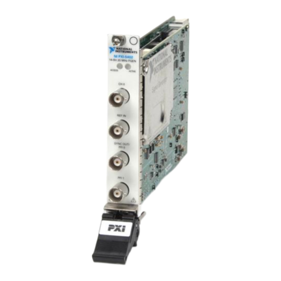
Page 24: Ni Pxi/Pci-5402/5406
ACTIVE CH 0 CH 0 REF IN SYNC OUT/ SYNC PFI 0 OUT/ PFI 0 PFI 1 NI PCI-5402 Figure 8. NI PXI/PCI-5402 Front Panel (NI PXI/PCI-5406 devices are similar) © National Instruments Corporation NI SIgnal Generators Getting Started Guide... - Page 25 Table 3. NI PXI/PCI-5402/5406 Front Panel Connectors Connector Access Function CH 0 Output Provides the waveform output. REF IN Input Accepts a PLL Reference clock from an external source and can frequency lock the Sample clock timebase to the external Reference clock. SYNC OUT/ Input/Output Provides a TTL-level output of the waveform...
-
Page 26: Ni Pxi-5404
SMB connectors, as shown in Figure 9. Signal descriptions are listed in Table 4. NI PXI-5404 100 MHz Freq Source ACCESS ACTIVE SINE CH 0 CLOCK PFI 0 Figure 9. NI PXI-5404 Front Panel © National Instruments Corporation NI SIgnal Generators Getting Started Guide... - Page 27 Table 4. NI PXI-5404 Front Panel Connectors Connector Access Function SINE Output Provides a sine waveform of the desired frequency output. CLOCK Output Provides a TTL version of the sine waveform being generated at the SINE connector. PFI 0 Input/Output Accepts either a TTL signal to start waveform generation, or provides an output to synchronize—or trigger—other devices at...
-
Page 28: Ni Pxi-5411/5431
ARB OUT VIDEO OUT EXT TRIG EXT TRIG MARKER OUT MARKER OUT PLL REF PLL REF SYNC OUT SYNC OUT VIDEO DIGITAL DIGITAL PATTERN PATTERN Figure 10. NI PXI-5411/5431 Front Panel © National Instruments Corporation NI SIgnal Generators Getting Started Guide... - Page 29 Table 5. NI PXI-5411/5431 Front Panel Connectors Connector Access Function ARB OUT/ Output Provides the waveform output. VIDEO OUT SYNC OUT Output Provides a TTL-level output of the waveform being generated at the ARB OUT connector. EXT TRIG Input Accepts a TTL-level signal that you can use to start or step through a waveform generation.
-
Page 30: Ni Pci-5411/5431
Routes the 16-bit digital pattern outputs, digital pattern clock output, marker output, external trigger input, and +5 V power output. Refer to the NI Signal Generators Help for connector pin assignments and signal descriptions. © National Instruments Corporation NI SIgnal Generators Getting Started Guide... -
Page 31: Ni Pxi/Pci-5412/5421/5422/5441
NI PXI/PCI-5412/5421/5422/5441 The NI 5412 is a 100 MS/s, 20 MHz, 14-bit arbitrary waveform generator. The NI 5421 is a 100 MS/s, 43 MHz, 16-bit arbitrary waveform generator. The NI 5422 is a 200 MS/s, 80 MHz, 16-bit arbitrary waveform generator. The NI 5441 is a 100 MS/s, 43 MHz, 16-bit arbitrary waveform generator with Onboard Signal Processing (OSP). - Page 32 Routes the 16-bit digital pattern outputs, digital DATA & pattern clock output, trigger outputs, trigger CONTROL inputs, and a clock input. Refer to the NI Signal (DDC) Generators Help for connector pin assignments and signal descriptions. © National Instruments Corporation NI SIgnal Generators Getting Started Guide...
-
Page 33: Ni Pxie-5442
NI PXIe-5442 The NI 5442 is a PXI Express, 100 MS/s, 43 MHz, 16-bit arbitrary waveform generator with Onboard Signal Processing (OSP). The NI 5442 has four SMB connectors, as shown in Figure 13. Signal descriptions are listed in Table 8. NI PXIe-5442 100 MS/s AWG OSP ACCESS... - Page 34 Refer to the NI Signal Generators Help for signal descriptions and routing information. © National Instruments Corporation NI SIgnal Generators Getting Started Guide...
-
Page 35: Where To Go For Support
Where to Go for Support The National Instruments Web site is your complete resource for technical support. At you have access to everything from ni.com/support troubleshooting and application development self-help resources to email and phone assistance from NI Application Engineers. - Page 36 National Instruments, NI, ni.com, and LabVIEW are trademarks of National Instruments Corporation. Refer to the Terms of Use section on ni.com/legal for more information about National Instruments trademarks. Other product and company names mentioned herein are trademarks or trade names of their respective companies. For patents covering National Instruments products, refer to the appropriate location: Help»Patents in your software, the patents.txt file on your CD, or ni.com/patents .
Need help?
Do you have a question about the PXI-5421 and is the answer not in the manual?
Questions and answers