National Instruments PXIe-5654 Getting Started Manual
Pxi rf analog signal generator
Hide thumbs
Also See for PXIe-5654:
- Calibration procedure (56 pages) ,
- Getting started manual (20 pages) ,
- Calibration procedure (32 pages)
Table of Contents
Advertisement
Quick Links
GETTING STARTED GUIDE
PXIe-5654
PXIe, 250 kHz to 20 GHz, PXI RF Analog Signal Generator
Note
Before you begin, install and configure your chassis and controller.
This document explains how to install, configure, and test the PXIe-5654 as a stand-alone
device. The PXIe-5654 is a 10 GHz or 20 GHz continuous-wave RF signal generator. The
PXIe-5654 requires the NI-RFSG instrument driver to program the device.
Refer to
ni.com/manuals
Safety Guidelines
Hot Surface
temperatures and cause burns. Allow the PXIe-5654 to cool before removing it from
the chassis.
Caution
the product in a manner not specified can damage the product and compromise the
built-in safety protection. Return damaged products to NI for repair.
Attention
documentation d'utilisation. L'utilisation du produit de toute autre façon que celle
spécifiée risque de l'endommager et de compromettre la protection de sécurité
intégrée. Renvoyez les produits endommagés à NI pour réparation.
Electromagnetic Compatibility Guidelines
This product was tested and complies with the regulatory requirements and limits for
electromagnetic compatibility (EMC) stated in the product specifications. These requirements
and limits are designed to provide reasonable protection against harmful interference when the
product is operated in the intended operational electromagnetic environment.
This product is intended for use in industrial locations. However, harmful interference may
occur in some installations, when the product is connected to a peripheral device or test object,
or if the product is used in residential or commercial areas. To minimize interference with
radio and television reception and prevent unacceptable performance degradation, install and
use this product in strict accordance with the instructions in the product documentation.
for the most recent specifications document.
If the PXIe-5654 has been in use, it may exceed safe handling
Observe all instructions and cautions in the user documentation. Using
Suivez toutes les instructions et respectez toutes les mises en garde de la
Advertisement
Table of Contents

Related Manuals for National Instruments PXIe-5654


Summary of Contents for National Instruments PXIe-5654
- Page 1 Before you begin, install and configure your chassis and controller. This document explains how to install, configure, and test the PXIe-5654 as a stand-alone device. The PXIe-5654 is a 10 GHz or 20 GHz continuous-wave RF signal generator. The PXIe-5654 requires the NI-RFSG instrument driver to program the device.
-
Page 2: Verifying The System Requirements
Do not install a device if it appears damaged in any way. Unpack any other items and documentation from the kit. Store the device in the antistatic package when the device is not in use. 2 | ni.com | PXIe-5654 Getting Started Guide... -
Page 3: Verifying The Kit Contents
Optional Items • A 1 N · m standard SMA torque wrench (NI part number 780487-01). • The PXIe-5696 amplitude extender (AE) module (NI part number 783128-01). PXIe-5654 Getting Started Guide | © National Instruments Corporation | 3... -
Page 4: Operating Environment
When the installer completes, restart your system. Installing the PXIe-5654 Notice To prevent damage to the PXIe-5654 caused by ESD or contamination, handle the module using the edges or the metal bracket. You must install NI-RFSG before installing the hardware. - Page 5 5. PXI Express Peripheral Slot 3. PXI Express Hybrid Peripheral Slot PXIe-5654 modules can be placed in PXI Express peripheral slots, PXI Express hybrid peripheral slots, or PXI Express system timing slots. Touch any metal part of the chassis to discharge static electricity.
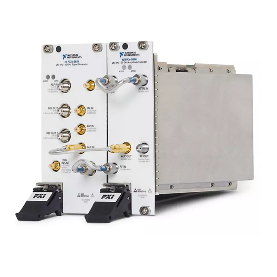
- Page 6 4 Installing the SMA Cables To use the PXIe-5654 with other devices, such as the NI 5696 AE, you must make connections using SMA cables. For best results when connecting signals to the PXIe-5654 front panel SMA connectors, use shielded low-loss coaxial cables.
- Page 7 PXIe-5654. Direct Connections to the PXIe-5654 The PXIe-5654 is a precision RF instrument that is sensitive to ESD and transients. Ensure you take the following precautions when making direct connections to the PXIe-5654 to avoid damaging the device.
- Page 8 PXIe-5654 RF Signal Generator Module The PXIe-5654 RF signal generator contains nine connectors and two multicolor LEDs. Figure 4. PXIe-5654 RF Signal Generator Module Front Panel 250 kHz–20 GHz Signal Generator ACCESS ACTIVE PULSE REF IN 1–20 MHz –0.5V MIN ±10 dBm NOM...
- Page 9 Amber The module is being accessed. Accessed means that the device setup is being transferred in order to control the device. Green The module is ready to be programmed by NI-RFSG. PXIe-5654 Getting Started Guide | © National Instruments Corporation | 9...
- Page 10 Programming the PXIe-5654 You can generate signals interactively using the NI-RFSG Soft Front Panel (SFP), or you can use the NI-RFSG instrument driver to program your device in the supported ADE of your choice. 10 | ni.com | PXIe-5654 Getting Started Guide...
- Page 11 You can locate LabVIEW or LabWindows/CVI examples with the NI Example Finder. Within LabVIEW or LabWindows/CVI, select Help»Find Examples and navigate to Hardware Input and Output»Modular Instruments. PXIe-5654 Getting Started Guide | © National Instruments Corporation | 11...
- Page 12 To verify your device configuration, use the NI-RFSG Soft Front Panel (SFP) in MAX to generate a simple signal. Within MAX, select the PXIe-5654 RF signal generator module in the configuration tree. Select Soft Front Panel from the MAX toolbar.
- Page 13 (100 MHz). 100M 12. In the VI front panel resource name control, enter the PXIe-5654 device name that you specified in MAX. Adding a While Loop Add a While Loop to continuously generate the signal and check the generation status until you click the Stop button.
- Page 14 Create an error indicator by right-clicking the error out output of the niRFSG Close VI and selecting Create»Indicator. Verify that the VI block diagram and VI front panel now look similar to the following figures. 14 | ni.com | PXIe-5654 Getting Started Guide...
- Page 15 Figure 9. Basic Sine Wave Generation VI Block Diagram Figure 10. Basic Sine Wave Generation VI Front Panel Open the VI front panel, and select the PXIe-5654 module name specified in MAX in the resource name control. Click the Run button on the toolbar to initiate sine wave generation.
-
Page 16: Troubleshooting
LED. Notice Apply external signals only while the PXIe-5654 is powered on. Applying external signals while the device is powered off may cause damage. Disconnect any signals from the module front panels. - Page 17 NI product. Product registration facilitates technical support and ensures that you receive important information updates from NI. NI corporate headquarters is located at 11500 N Mopac Expwy, Austin, TX, 78759-3504, USA. PXIe-5654 Getting Started Guide | © National Instruments Corporation | 17...
- Page 18 NI trademarks. Other product and company names mentioned herein are trademarks or trade names of their respective companies. For patents covering NI products/technology, refer to the appropriate location: Help»Patents in your software, the file on your media, or the National Instruments Patent Notice at . You can find patents.txt ni.com/patents...
Need help?
Do you have a question about the PXIe-5654 and is the answer not in the manual?
Questions and answers