National Instruments PXIe-5654 Calibration Procedure
250 khz to 20 ghz rf analog signal generator
Hide thumbs
Also See for PXIe-5654:
- Calibration procedure (56 pages) ,
- Getting started manual (20 pages) ,
- Getting started manual (18 pages)
Table of Contents
Advertisement
Quick Links
Download this manual
See also:
Calibration Procedure
CALIBRATION PROCEDURE
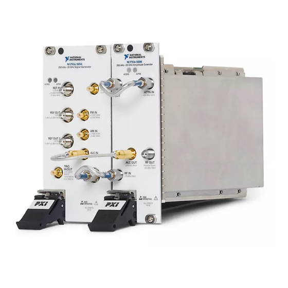
PXIe-5654
250 kHz to 20 GHz RF Analog Signal Generator
This document contains the verification and adjustment procedures for the PXIe-5654 RF
Analog Signal Generator.
Refer to
ni.com/calibration
Contents
Required Software.....................................................................................................................2
Related Documentation.............................................................................................................2
Test Equipment..........................................................................................................................2
Test Conditions..........................................................................................................................6
Initial Setup............................................................................................................................... 7
Test System Characterization....................................................................................................7
Zeroing and Calibrating the Power Sensor....................................................................... 7
As-Found and As-Left Limits................................................................................................... 7
Verification................................................................................................................................8
Verifying 10 MHz Reference Frequency Accuracy.......................................................... 8
Verifying 10 MHz Reference Amplitude Accuracy........................................................10
Verifying 100 MHz Reference Frequency Accuracy...................................................... 12
Verifying 100 MHz Reference Amplitude Accuracy......................................................13
Verifying RF OUT Frequency Accuracy........................................................................ 15
Verifying RF OUT Phase Noise......................................................................................17
Verifying RF OUT Maximum Power..............................................................................19
Optional Verification...............................................................................................................21
Verifying RF OUT Amplitude Accuracy........................................................................ 21
Verifying RF OUT Minimum Power.............................................................................. 23
Verifying PULSE IN Operation...................................................................................... 25
Adjustment.............................................................................................................................. 27
Adjusting Frequency Reference Accuracy......................................................................27
Adjusting RF OUT Power...............................................................................................29
Reverification..........................................................................................................................30
Updating Calibration Date and Time...................................................................................... 30
Worldwide Support and Services............................................................................................ 30
for more information about calibration solutions.
Advertisement
Table of Contents

Subscribe to Our Youtube Channel
Related Manuals for National Instruments PXIe-5654


Summary of Contents for National Instruments PXIe-5654
-
Page 1: Table Of Contents
CALIBRATION PROCEDURE PXIe-5654 250 kHz to 20 GHz RF Analog Signal Generator This document contains the verification and adjustment procedures for the PXIe-5654 RF Analog Signal Generator. Refer to ni.com/calibration for more information about calibration solutions. Contents Required Software........................2 Related Documentation......................2 Test Equipment..........................2... -
Page 2: Required Software
Required Software Calibrating the PXIe-5654 requires you to install the following package on the calibration system: • NI-RFSG 14.5 or later You can download all required software from ni.com/downloads. The software supports programming the verification procedures in the LabVIEW, C, and ™... - Page 3 8040C Rubidium • 10 MHz reference Frequency accuracy: Frequency Standard frequency accuracy ±1 × 10 • 100 MHz reference frequency accuracy • RF OUT frequency accuracy Adjustments: • Frequency reference accuracy PXIe-5654 Calibration Procedure | © National Instruments | 3...
- Page 4 Table 1. Recommended Equipment for PXIe-5654 Calibration (Continued) Equipment Recommended Where Used Minimum Model Requirements Power meter Anritsu ML2438A Verifications: Range: -15 dBm to with a SC7413A 20 dBm • 10 MHz reference Power Sensor amplitude accuracy Frequency range: •...
- Page 5 The connector on the power sensor listed above may be difficult to access with a torque wrench when there is adjacent connected hardware. Use this adapter if you need to extend the capabilities of the power sensor to make it accessible by a torque wrench. PXIe-5654 Calibration Procedure | © National Instruments | 5...
-
Page 6: Test Conditions
• PULSE IN operation Test Conditions The following setup and environmental conditions are required to ensure the PXIe-5654 meets published specifications. • Keep cabling as short as possible. Long cables act as antennas, picking up extra noise that can affect measurements. -
Page 7: Initial Setup
• Frequencies less than and equal to 10 GHz apply to the 10 GHz and 20 GHz PXIe-5654; frequencies above 10 GHz apply only to the 20 GHz PXIe-5654. Initial Setup Refer to the PXIe-5654 Getting Started Guide for information about how to install the software and the hardware and how to configure the device in Measurement &... -
Page 8: Verification
This procedure verifies that the internal oven-controlled crystal oscillator (OCXO) is adjusted for correct frequency accuracy. Connect the PXIe-5654 REF OUT 10 MHz front panel connector to the signal source analyzer RF input connector using the K(m)-to-K(m) cable as shown in the following figure. - Page 9 Check the signal generation status and verify that there are no reported errors or warnings. Configure the signal source analyzer using the following settings: • Center frequency: 110 MHz • Reference level: -50 dBm PXIe-5654 Calibration Procedure | © National Instruments | 9...
-
Page 10: Verifying 10 Mhz Reference Amplitude Accuracy
This procedure verifies that the internal 10 MHz reference circuitry is adjusted for correct amplitude accuracy. Connect the power sensor to the PXIe-5654 REF OUT 10 MHz front panel connector as shown in the following figure. 10 | ni.com | PXIe-5654 Calibration Procedure... - Page 11 Check the signal generation status and verify that there are no reported errors or warnings. Measure the PXIe-5654 REF OUT 10 MHz front panel connector power using the power meter. Correct the power meter reading for the 10 MHz measurement frequency and ensure that the corrected power is between 3 dBm and 7 dBm.
-
Page 12: Verifying 100 Mhz Reference Frequency Accuracy
This procedure verifies that the internal 100 MHz reference circuitry is adjusted for correct frequency accuracy. Connect the PXIe-5654 REF OUT 2 100 MHz front panel connector to the signal source analyzer RF input connector using the K(m)-to-K(m) cable as shown in the following figure. -
Page 13: Verifying 100 Mhz Reference Amplitude Accuracy
This procedure verifies that the internal 100 MHz reference circuitry is adjusted for correct amplitude accuracy. Connect the power sensor to the PXIe-5654 REF OUT 2 100 MHz front panel connector as shown in the following figure. PXIe-5654 Calibration Procedure | © National Instruments | 13... - Page 14 Check the signal generation status and verify that there are no reported errors or warnings. Use the power meter to measure the PXIe-5654 REF OUT 2 100 MHz front panel connector power. Correct the power meter reading for the 100 MHz measurement frequency. Ensure that the corrected power is between 3 dBm and 7 dBm.
-
Page 15: Verifying Rf Out Frequency Accuracy
This procedure verifies that the internal signal generation circuitry is adjusted for correct frequency accuracy. Connect the PXIe-5654 RF OUT front panel connector to the signal source analyzer RF input connector using the K(m)-to-K(m) cable as shown in the following figure. - Page 16 Configure the PXIe-5654 using the following settings: • Frequency: Frequency from the list in step 3 • Power Level: 0 dBm • Reference Clock Source: Onboard Clock Commit the settings to hardware if this is the first iteration of running this procedure;...
-
Page 17: Verifying Rf Out Phase Noise
This procedure verifies that the internal frequency generation circuitry is adjusted for correct phase noise accuracy. Connect the PXIe-5654 RF OUT front panel connector to the signal source analyzer RF input connector using the K(m)-to-K(m) cable as shown in the following figure. - Page 18 3 kHz 1,000 300 kHz to 1 MHz 10 kHz 1,000 Configure the PXIe-5654 using the following settings: • Frequency: 500 MHz • Power Level: +8 dBm Commit the settings to hardware if this is the first iteration of running this procedure;...
-
Page 19: Verifying Rf Out Maximum Power
This procedure verifies that the internal signal generation circuitry produces the correct maximum output power. Connect the power sensor to the PXIe-5654 RF OUT front panel connector as shown in the following figure. PXIe-5654 Calibration Procedure | © National Instruments | 19... - Page 20 1. PXIe-5654 RF Analog Signal Generator 2. Power Meter 3. Power Sensor Initialize a new external calibration session for the PXIe-5654. Create a list of test frequencies using the following table. Table 6. RF OUT Maximum Power Test Frequencies Start Frequency (MHz)
-
Page 21: Optional Verification
This procedure verifies that the internal signal generation circuitry is adjusted for correct amplitude accuracy. Connect the power sensor to the PXIe-5654 RF OUT front panel connector as shown in the following figure. PXIe-5654 Calibration Procedure | © National Instruments | 21... - Page 22 1. PXIe-5654 RF Analog Signal Generator 2. Power Meter 3. Power Sensor Create a new device session for the PXIe-5654. Create a list of test frequencies using the settings in the following table. Table 8. RF OUT Amplitude Accuracy Test Settings...
-
Page 23: Verifying Rf Out Minimum Power
This procedure verifies that the internal signal generation circuitry can produce the correct minimum output power. Connect the power sensor to the PXIe-5654 RF OUT front panel connector as shown in the following figure. PXIe-5654 Calibration Procedure | © National Instruments | 23... - Page 24 1. PXIe-5654 RF Analog Signal Generator 2. Power Meter 3. Power Sensor Initialize a new external calibration session for the PXIe-5654. Create a list of test frequencies using the following table. Table 10. RF OUT Minimum Power Test Frequencies Start Frequency (MHz)
-
Page 25: Verifying Pulse In Operation
Verifying PULSE IN Operation This procedure verifies that the PXIe-5654 PULSE IN connection is functioning. Connect the signal source analyzer RF input to the PXIe-5654 RF OUT front panel connector using the K(m)-to-K(m) cable. Connect the Port 0, Line 0 (P0.0) output of the USB digital output device to two separate connectors using a BNC Tee connector and a BNC(m)-to-terminal block adapter. - Page 26 1. USB-6501 Digital I/O Device 4. K(m)-to-K(m) Cable 2. BNC(m)-to-SMB(f) Cable 5. Signal Source Analyzer 3. PXIe-5654 RF Analog Signal Generator Create a new device session for the PXIe-5654. Configure the signal source analyzer using the following settings: • Reference level: 5 dBm •...
-
Page 27: Adjustment
This adjustment yields a more accurately tuned voltage-controlled oscillator (VCO) frequency. Connect the PXIe-5654 RF OUT front panel connector to the signal source analyzer RF input connector using the K(m)-to-K(m) cable as shown in the following figure. PXIe-5654 Calibration Procedure | © National Instruments | 27... - Page 28 Use the signal source analyzer to measure the frequency at the peak of the signal. Use the frequency measured in step 6 as the value of the measured frequency input of the niRFSG 5654 OCXO Cal Adjust VI. 28 | ni.com | PXIe-5654 Calibration Procedure...
-
Page 29: Adjusting Rf Out Power
This procedure adjusts the PXIe-5654 RF OUT power using a power meter. This adjustment yields a more accurate output power for the PXIe-5654 RF OUT front panel connectors. Connect the power sensor to the PXIe-5654 RF OUT front panel connector as shown in the following figure. -
Page 30: Reverification
PXIe-5654. Note If any test fails reverification after performing an adjustment, verify that you have met the test conditions before returning your PXIe-5654 to NI. Refer to the Worldwide Support and Services section for information about support resources or service requests. - Page 31 United States, visit the Worldwide Offices section of ni.com/niglobal access the branch office websites, which provide up-to-date contact information. PXIe-5654 Calibration Procedure | © National Instruments | 31...
- Page 32 NI trademarks. Other product and company names mentioned herein are trademarks or trade names of their respective companies. For patents covering NI products/technology, refer to the appropriate location: Help»Patents in your software, the file on your media, or the National Instruments Patent Notice at . You can find patents.txt ni.com/patents...
Need help?
Do you have a question about the PXIe-5654 and is the answer not in the manual?
Questions and answers