National Instruments PXIe-5654 Calibration Procedure
10 ghz or 20 ghz rf analog signal generator with amplitude extender
Hide thumbs
Also See for PXIe-5654:
- Calibration procedure (38 pages) ,
- Getting started manual (20 pages) ,
- Getting started manual (18 pages)
Table of Contents
Advertisement
Quick Links
CALIBRATION PROCEDURE
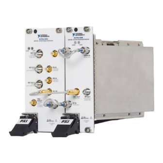
PXIe-5654 with PXIe-5696
10 GHz or 20 GHz RF Analog Signal Generator with Amplitude
Extender
This document contains the verification and adjustment procedures for the PXIe-5654 RF
Analog Signal Generator when used with the PXIe-5696 Amplitude Extender.
Refer to
ni.com/calibration
Contents
Required Software.....................................................................................................................2
Related Documentation.............................................................................................................2
Test Equipment..........................................................................................................................2
Test Conditions..........................................................................................................................5
Initial Setup............................................................................................................................... 6
Test System Characterization....................................................................................................6
Zeroing and Calibrating the Power Sensor....................................................................... 6
Characterizing the Power Sensor with 20 dB Attenuator................................................. 6
Characterizing the Signal Source Analyzer...................................................................... 8
As-Found and As-Left Limits................................................................................................. 10
Verification.............................................................................................................................. 11
Verifying 10 MHz Reference Frequency Accuracy........................................................ 11
Verifying 10 MHz Reference Amplitude Accuracy........................................................13
Verifying 100 MHz Reference Frequency Accuracy...................................................... 15
Verifying 100 MHz Reference Amplitude Accuracy......................................................16
Verifying RF OUT Frequency Accuracy........................................................................ 18
Verifying RF OUT Phase Noise......................................................................................20
Verifying RF OUT Amplitude Accuracy........................................................................ 22
Verifying RF OUT Maximum Power..............................................................................30
Verifying Frequency Settling.......................................................................................... 31
Optional Verification...............................................................................................................36
Verifying PULSE IN Operation...................................................................................... 36
Adjustment.............................................................................................................................. 38
Adjusting Frequency Reference Accuracy......................................................................38
Adjusting RF OUT Power...............................................................................................40
Measuring RF Attenuator Path Input Power...................................................................41
Adjusting RF Attenuator Path.........................................................................................43
Adjusting RF Attenuator Accuracy.................................................................................44
Measuring Amplifier Path Input Power.......................................................................... 46
Adjusting Amplitude Accuracy (Low Harmonic Paths).................................................48
for more information about calibration solutions.
Advertisement
Table of Contents

Related Manuals for National Instruments PXIe-5654


Summary of Contents for National Instruments PXIe-5654
-
Page 1: Table Of Contents
PXIe-5654 with PXIe-5696 10 GHz or 20 GHz RF Analog Signal Generator with Amplitude Extender This document contains the verification and adjustment procedures for the PXIe-5654 RF Analog Signal Generator when used with the PXIe-5696 Amplitude Extender. Refer to ni.com/calibration for more information about calibration solutions. -
Page 2: Required Software
Adjusting Amplitude Accuracy (High Power Paths)............50 Adjusting ALC........................ 52 Reverification..........................54 Updating Calibration Date and Time..................54 Worldwide Support and Services.................... 54 Required Software Calibrating the PXIe-5654 requires you to install one of the following packages on the calibration system: • NI-RFSG 14.5 • NI-RFSA 14.5 Note NI-RFSG automatically installs when you install NI-RFSA. - Page 3 ±5 × 10 frequency accuracy • RF OUT frequency accuracy • PULSE IN operation Arbitrary PXIe-5451 Verifications: waveform Waveform • Frequency settling generator Generator • PULSE IN (optional) (AWG) PXIe-5654 with PXIe-5696 Calibration Procedure | © National Instruments | 3...
- Page 4 Loss: <0.7 dB/ft. frequency accuracy (typical) at 20 GHz • 100 MHz reference frequency accuracy • RF OUT frequency accuracy • RF OUT phase noise • RF OUT maximum power • Frequency settling 4 | ni.com | PXIe-5654 with PXIe-5696 Calibration Procedure...
-
Page 5: Test Conditions
• Allow a warm-up time of at least 30 minutes after the chassis is powered on. The warm- up time ensures that the PXIe-5654 and PXIe-5696 are at a stable operating temperature. • Use an appropriate torque wrench to tighten all module RF connectors (SMA, 3.5 mm, or K). -
Page 6: Initial Setup
• Frequencies less than and equal to 10 GHz apply to the 10 GHz and 20 GHz PXIe-5654; frequencies above 10 GHz apply only to the 20 GHz PXIe-5654. • The PXIe-5654 must be verified before performing the procedures in this document. - Page 7 Measure the PXIe-5654 output power with the power meter. Correct the power meter reading for the RF frequency. Attach the 20 dB attenuator between the PXIe-5654 and the power sensor as shown in the following figure. PXIe-5654 with PXIe-5696 Calibration Procedure | © National Instruments | 7...
-
Page 8: Characterizing The Signal Source Analyzer
Attenuator Loss = Measurement with Attenuator - Measurement without Attenuator Characterizing the Signal Source Analyzer Connect the power sensor to the PXIe-5654 RF OUT front panel connector as shown in the following figure. 8 | ni.com | PXIe-5654 with PXIe-5696 Calibration Procedure... - Page 9 3. Power Sensor Set the PXIe-5654 to -40 dBm output. Step the PXIe-5654 frequency in 10 MHz steps according to the frequency range of your PXIe-5654 model, as shown in the following table. Table 3. Frequency Steps (10 MHz) for PXIe-5654 Models...
-
Page 10: As-Found And As-Left Limits
Power Sensor As-Found and As-Left Limits The as-found limits are the published specifications for the PXIe-5654. NI uses these limits to determine whether the PXIe-5654 meets the specifications when it is received for calibration. Use the as-found limits during initial verification. -
Page 11: Verification
The as-left calibration limits are equal to the published NI specifications for the PXIe-5654, less guard bands for measurement uncertainty, temperature drift, and drift over time. NI uses these limits to reduce the probability that the instrument will be outside the published specification limits at the end of the calibration cycle. - Page 12 2. Signal Source Analyzer 3. K(m)-to-K(m) Cable Create a new device session for the PXIe-5654. Set the PXIe-5654 RF frequency to 4 GHz, 0 dBm. Export the reference clock to the RefOut terminal. Initiate signal generation. Disable the RF output.
-
Page 13: Verifying 10 Mhz Reference Amplitude Accuracy
This procedure verifies that the internal 10 MHz reference circuitry is adjusted for correct amplitude accuracy. Connect the power sensor to the PXIe-5654 REF OUT 10 MHz front panel connector as shown in the following figure. PXIe-5654 with PXIe-5696 Calibration Procedure | © National Instruments | 13... - Page 14 Check the signal generation status and verify that there are no reported errors or warnings. Measure the PXIe-5654 REF OUT 10 MHz front panel connector power using the power meter. Correct the power meter reading for the 10 MHz measurement frequency and ensure that the corrected power is between 3 dBm and 7 dBm.
-
Page 15: Verifying 100 Mhz Reference Frequency Accuracy
This procedure verifies that the internal 100 MHz reference circuitry is adjusted for correct frequency accuracy. Connect the PXIe-5654 REF OUT 2 100 MHz front panel connector to the signal source analyzer RF IN front panel connector using the K(m)-to-K(m) cable as shown in the following figure. -
Page 16: Verifying 100 Mhz Reference Amplitude Accuracy
This procedure verifies that the internal 100 MHz reference circuitry is adjusted for correct amplitude accuracy. Connect the power sensor to the PXIe-5654 REF OUT 2 100 MHz front panel connector as shown in the following figure. 16 | ni.com | PXIe-5654 with PXIe-5696 Calibration Procedure... - Page 17 Check the signal generation status and verify that there are no reported errors or warnings. Use the power meter to measure the PXIe-5654 REF OUT 2 100 MHz front panel connector power. Correct the power meter reading for the 100 MHz measurement frequency. Ensure that the corrected power is between 3 dBm and 7 dBm.
-
Page 18: Verifying Rf Out Frequency Accuracy
Create a new device session for the PXIe-5654. Create a list of test frequencies, including endpoints, containing 100 MHz and 1 GHz according to the frequency range of your PXIe-5654 model, as shown in the following table. 18 | ni.com | PXIe-5654 with PXIe-5696 Calibration Procedure... - Page 19 Aging = ±(0.01 ppm × Number of Days Since Last Adjustment) Temperature Stability (15 °C to 35 °C) = ±0.2 ppm 15. Repeat steps 6 through 13 for each subsequent point in the frequency array created in step 4. PXIe-5654 with PXIe-5696 Calibration Procedure | © National Instruments | 19...
-
Page 20: Verifying Rf Out Phase Noise
50 Ω ALL PORTS 50 Ω 1. PXIe-5654 RF Analog Signal Generator 3. Signal Source Analyzer 2. PXIe-5696 Amplitude Extender 4. K(m)-to-K(m) Cable Create a new device session for the PXIe-5654. 20 | ni.com | PXIe-5654 with PXIe-5696 Calibration Procedure... - Page 21 11. Measure the phase noise using the signal source analyzer. Record the measurements. 12. Ensure that the recorded measurements are within the limits set in the following tables. PXIe-5654 with PXIe-5696 Calibration Procedure | © National Instruments | 21...
-
Page 22: Verifying Rf Out Amplitude Accuracy
13. Repeat steps 6 through 12 for 1 GHz, 5 GHz, 10 GHz, and 20 GHz carrier frequencies. Verifying RF OUT Amplitude Accuracy This procedure verifies that the PXIe-5654 with PXIe-5696 is adjusted for correct amplitude accuracy. Connect the PXIe-5654 to the PXIe-5696. - Page 23 Create a new device session for the PXIe-5654. Create a list of test frequencies from the following table that apply to power levels that are greater than or equal to 10 dBm. PXIe-5654 with PXIe-5696 Calibration Procedure | © National Instruments | 23...
- Page 24 6,000 6,250 15,000 15,250 20,000 0.25 — — 112.5 1,000 1,250 3,000 3,250 6,000 6,250 15,000 15,250 20,000 0.25 — — 112.5 1,000 1,250 3,000 3,250 6,000 6,250 15,000 15,250 20,000 24 | ni.com | PXIe-5654 with PXIe-5696 Calibration Procedure...
- Page 25 3,000 3,250 6,000 6,250 15,000 15,250 20,000 0.25 — — 112.5 1,000 1,250 3,000 3,250 6,000 6,250 15,000 15,250 20,000 0.25 — — 112.5 15,250 20,000 1,000 6,250 15,000 PXIe-5654 with PXIe-5696 Calibration Procedure | © National Instruments | 25...
- Page 26 Check the signal generation status and verify that there are no reported errors or warnings. Measure the PXIe-5654 RF OUT front panel connector power using the power meter. Correct the power meter reading for the RF frequency. This measurement is the Measured Power (dBm).
- Page 27 12. Repeat steps 6 through 8 for each test frequency in the frequency list created in step 4. 13. Repeat steps 6 through 11 for all output powers greater than -10 dBm and less than +10 dBm in the frequency list. PXIe-5654 with PXIe-5696 Calibration Procedure | © National Instruments | 27...
- Page 28 19. Disconnect the power sensor from the PXIe-5696. 20. Connect the signal source analyzer to the PXIe-5696 RF OUT front panel connector using the K(m)-to-K(m) cable as shown in the following figure. 28 | ni.com | PXIe-5654 with PXIe-5696 Calibration Procedure...
- Page 29 22. Repeat steps 4 through 15 for output powers from -80 dBm to -40 dBm, inclusive. Correct the signal source reading for the RF frequency using the calibration data previously measured for the signal source analyzer. 23. Close the device session. PXIe-5654 with PXIe-5696 Calibration Procedure | © National Instruments | 29...
-
Page 30: Verifying Rf Out Maximum Power
Verifying RF OUT Maximum Power This procedure verifies that the PXIe-5654 with PXIe-5696 produces the correct maximum output power. Connect the PXIe-5654 to the PXIe-5696. Connect the power sensor through the 20 dB attenuator to the PXIe-5696 RF OUT front panel connector. -
Page 31: Verifying Frequency Settling
15,000 15,250 20,000 Set the PXIe-5654 to the frequency and power from the list created in step 4. Initiate signal generation. Measure the PXIe-5696 RF OUT front panel connector power using the power meter and 20 dB attenuator. Correct the power meter reading for the RF frequency and previously characterized 20 dB attenuator loss. - Page 32 Connect the PXIe-5451 CH 1+/Q+ output to the signal source analyzer rear panel EXT TRIG/GATE IN connector. (Not pictured.) Connect the PXIe-5451 CH 1+/Q+ output to the PXIe-5654 front panel TRIG IN/OUT connector as shown in the following figure. Figure 15. Frequency Settling Verification Equipment Setup...
- Page 33 164.96 20,602.51 20,602.51 10,557.49 10,557.49 20,602.51 Configure the PXIe-5654 for the frequency list created in step 5 using the following settings: • Configuration List Step Trigger Type: Digital edge • Configuration List Step Digital Edge Source: TrigIn Configure the signal source analyzer using the following setting: •...
- Page 34 External trigger level: 1 V • Configure trigger polarity: Positive • Sweep time: Settling time from Tables 10 and 11 • Sweep time: Coupled 23. Wait 1 second. 24. Repeat steps 8 through 11. 34 | ni.com | PXIe-5654 with PXIe-5696 Calibration Procedure...
- Page 35 ≤1,115 160.957 10,557.49 ≤100 ≤90 ≤1,000 ≤970 10,557.49 160.957 ≤1,150 ≤1,115 ≤2,000 ≤1,900 10,000 ≤1,150 ≤1,115 ≤2,000 ≤1,900 10,000 ≤100 ≤90 ≤1,000 ≤970 10,000 2,000 ≤100 ≤90 ≤1,000 ≤970 PXIe-5654 with PXIe-5696 Calibration Procedure | © National Instruments | 35...
-
Page 36: Optional Verification
34. Close the PXIe-5654 session. 35. Close the signal source analyzer session. Optional Verification Use the following procedures to verify nonwarranted specifications for the PXIe-5654. Verifying PULSE IN Operation This procedure verifies that the PXIe-5654 PULSE IN connection is functioning. - Page 37 RF attenuation: 30 dB Configure the PXIe-5654 using the following settings: • Pulse Modulation Enabled: TRUE • Frequency: 5 GHz • Power Level: 10 dBm • Output Enabled: TRUE PXIe-5654 with PXIe-5696 Calibration Procedure | © National Instruments | 37...
-
Page 38: Adjustment
OnPower - OffPower ≥ 80 dB 12. Stop signal generation. 13. Close the instrument sessions. Adjustment This section describes the steps needed to adjust the PXIe-5654 with PXIe-5696 to meet published specifications. Note The PXIe-5696 is adjusted while connected to the PXIe-5654. - Page 39 Call the niRFSG 5654 OCXO Cal Initialize VI. Call the niRFSG 5654 OCXO Cal Configure VI. Use the signal source analyzer to measure the frequency at the peak of the signal. PXIe-5654 with PXIe-5696 Calibration Procedure | © National Instruments | 39...
-
Page 40: Adjusting Rf Out Power
This procedure adjusts the PXIe-5654 RF OUT power using a power meter. This adjustment yields a more accurate output power for the PXIe-5654 RF OUT front panel connectors. Connect the power sensor to the PXIe-5654 RF OUT front panel connector as shown in the following figure. -
Page 41: Measuring Rf Attenuator Path Input Power
Using the measured input power yields a more accurate adjustment for the PXIe-5696 attenuator paths. Connect the PXIe-5654 RF OUT front panel connector to the power meter through the 20 dB attenuator as shown in the following figure. PXIe-5654 with PXIe-5696 Calibration Procedure | © National Instruments | 41... - Page 42 Call the niRFSG 5696 Attenuator Path Cal Configure VI. Measure the PXIe-5654 output power through the 20 dB attenuator with the power meter. Ensure that the power meter is settled within 0.1% before taking a measurement. Correct the power meter reading for the RF frequency using the frequency to measure output of the niRFSG 5696 Attenuator Path Cal Configure VI.
-
Page 43: Adjusting Rf Attenuator Path
PXIe-5696 EE PROM. This adjustment yields a more accurate output power for the PXIe-5696 RF OUT. Connect the PXIe-5654 RF OUT to the PXIe-5696 ATTN IN front panel connector through the 20 dB attenuator as shown in the following figure. -
Page 44: Adjusting Rf Attenuator Accuracy
PXIe-5696 EEPROM. This adjustment yields a more accurate output power for the PXIe-5696 RF OUT. Connect the power sensor directly to the PXIe-5696 RF OUT front panel connector as shown in the following figure. 44 | ni.com | PXIe-5654 with PXIe-5696 Calibration Procedure... - Page 45 5696 Attenuator Cal Adjust VI. Repeat steps 5 and 6 until the attenuator calibration complete output of the niRFSG 5696 Attenuator Cal Adjust VI returns a value of TRUE. PXIe-5654 with PXIe-5696 Calibration Procedure | © National Instruments | 45...
-
Page 46: Measuring Amplifier Path Input Power
This procedure measures the input power used for PXIe-5696 RF amplifier path adjustments. Using the measured input power yields a more accurate adjustment. Connect the PXIe-5654 RF OUT front panel connector directly to the power meter as shown in the following figure. - Page 47 Call the niRFSG 5696 Amplifier Cal Configure VI. Measure the PXIe-5654 output power with the power meter. Ensure that the power meter is settled within 0.1% before taking a measurement. Correct the measurement from step 6 using the frequency to measure output of the niRFSG 5696 Amplifier Cal Configure VI.
-
Page 48: Adjusting Amplitude Accuracy (Low Harmonic Paths)
PXIe-5696 EEPROM. This adjustment yields a more accurate output power for the PXIe-5696 RF OUT. Connect the power sensor directly to the PXIe-5696 RF OUT front panel connector as shown in the following figure. 48 | ni.com | PXIe-5654 with PXIe-5696 Calibration Procedure... - Page 49 Measure the PXIe-5696 output power with the power meter. Correct the measurement using the frequency to measure output of the niRFSG 5696 Amplifier Cal Configure VI. Ensure that the power meter is settled within 0.1% before taking a reading. PXIe-5654 with PXIe-5696 Calibration Procedure | © National Instruments | 49...
-
Page 50: Adjusting Amplitude Accuracy (High Power Paths)
PXIe-5696 EEPROM. This adjustment yields a more accurate output power for the PXIe-5696 RF OUT. Connect the power sensor directly to the PXIe-5696 RF OUT front panel connector as shown in the following figure. 50 | ni.com | PXIe-5654 with PXIe-5696 Calibration Procedure... - Page 51 Measure the PXIe-5696 output power with the power meter. Correct the measurement using the frequency to measure output of the niRFSG 5696 Amplifier Cal Configure VI. Ensure that the power meter is settled within 0.1% before taking a reading. PXIe-5654 with PXIe-5696 Calibration Procedure | © National Instruments | 51...
-
Page 52: Adjusting Alc
Measuring Amplifier Path Input Power on page 46 Adjusting ALC This procedure characterizes the ALC path in the PXIe-5654 with PXIe-5696 and updates the values stored in the PXIe-5696 EEPROM. This adjustment yields a more accurate output power for the PXIe-5696 RF OUT. - Page 53 Repeat steps 5 and 6 until ALC calibration complete output of the niRFSG 5696 ALC Cal Adjust VI returns a value of TRUE. Call the niRFSG Close External Calibration VI to close the session. PXIe-5654 with PXIe-5696 Calibration Procedure | © National Instruments | 53...
-
Page 54: Reverification
PXIe-5654 or the PXIe-5696. Note If any test fails reverification after performing an adjustment, verify that you have met the test conditions before returning your PXIe-5654 or PXIe-5696 to NI. Refer to the Worldwide Support and Services section for information about support resources or service requests. - Page 55 PXIe-5654 with PXIe-5696 Calibration Procedure | © National Instruments | 55...
- Page 56 CONTAINED HEREIN AND SHALL NOT BE LIABLE FOR ANY ERRORS. U.S. Government Customers: The data contained in this manual was developed at private expense and is subject to the applicable limited rights and restricted data rights as set forth in FAR 52.227-14, DFAR 252.227-7014, and DFAR 252.227-7015. © 2016 National Instruments. All rights reserved. 376183A-01 Nov16...
Need help?
Do you have a question about the PXIe-5654 and is the answer not in the manual?
Questions and answers