Table of Contents
Advertisement
Quick Links
CALIBRATION PROCEDURE
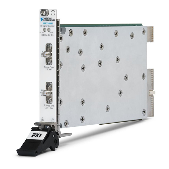
NI PXI-5650/5651/5652
This document describes the processes to calibrate the NI PXI-5650/5651/5652 (PXI-5650/
5651/5652) RF signal generator. This document provides performance tests to verify whether
the instrument is performing within the published specifications. For more information about
calibration, visit
ni.com/calibration
Contents
Required Software .................................................................................................................... 2
Related Documentation ............................................................................................................ 2
Password ................................................................................................................................... 2
Calibration Interval................................................................................................................... 2
Test Equipment......................................................................................................................... 3
Test Conditions......................................................................................................................... 5
Calibration Procedures ............................................................................................................. 5
Initial Setup....................................................................................................................... 6
Characterizing the Test System ........................................................................................ 6
Characterizing the Spectrum Analyzer..................................................................... 6
Verification....................................................................................................................... 8
Validating the ALC Limits Table............................................................................. 8
Verifying Frequency Accuracy ................................................................................ 9
Verifying High Power Level Accuracy .................................................................... 9
Verifying Low Power Level Accuracy..................................................................... 11
Verifying Single Sideband Phase Noise at 10 kHz Offset ....................................... 13
Verifying Nonharmonics at 0 dBm to -20 dBm Output Power ................................ 15
Optional Verification ........................................................................................................ 19
Verifying Harmonics at 0 dBm (Functional Test).................................................... 19
Verifying Harmonics at -50 dBm (Functional Test) ................................................ 21
Verifying Subharmonics on the PXI-5652 at 0 dBm (Functional Test)................... 23
Verifying Subharmonics on the PXI-5652 at -50 dBm (Functional Test) ............... 25
Adjustment........................................................................................................................ 27
Adjusting ALC ......................................................................................................... 27
Adjusting Attenuators............................................................................................... 28
Adjusting ALC Limits .............................................................................................. 29
Adjusting Frequency Accuracy ................................................................................ 30
Updating Calibration Date and Time................................................................................ 30
Appendix A: Calibration Utilities............................................................................................. 31
Calibration VI References ................................................................................................ 31
Worldwide Support and Services ............................................................................................. 31
.
Advertisement
Table of Contents

Subscribe to Our Youtube Channel
Related Manuals for National Instruments PXI-5650


Summary of Contents for National Instruments PXI-5650
-
Page 1: Table Of Contents
CALIBRATION PROCEDURE NI PXI-5650/5651/5652 This document describes the processes to calibrate the NI PXI-5650/5651/5652 (PXI-5650/ 5651/5652) RF signal generator. This document provides performance tests to verify whether the instrument is performing within the published specifications. For more information about calibration, visit ni.com/calibration... -
Page 2: Required Software
Required Software To calibrate the PXI-5650/5651/5652, you must install NI-RFSG version 15.0.3 or later on the calibration system. NI-RFSG includes all the VIs necessary for calibration. You can download the latest version of NI-RFSG at ni.com/downloads NI-RFSG supports programming the calibration procedures in LabVIEW. Calibration VIs are accessible in LabVIEW from the Functions palette. -
Page 3: Test Equipment
Test Equipment Table 2 lists the equipment required to calibrate the PXI-5650/5651/5652. If you do not have the recommended equipment, select a substitute calibration standard using the specifications listed in Table 2. Table 2. Required Equipment Specifications for PXI-5650/5651/5652 Calibration... - Page 4 VSWR: ≤1 .25 : 1 up to 6.6 GHz N (m)-to- Radiall — Frequency range: SMA (f) R191.329.000 DC to 11 GHz adapter Impedance: 50 Ω PXI chassis NI PXIe-1065 — — 4 | ni.com | NI PXI-5650/5651/5652 Calibration Procedure...
-
Page 5: Test Conditions
Test Conditions The following setup and environmental conditions are required to ensure the PXI-5650/5651/ 5652 meets published specifications. • Keep cabling as short as possible. Long cables and wires act as antennas, picking up extra noise that can affect measurements. -
Page 6: Initial Setup
Return Device Complete Initial Setup Refer to the NI PXI-5650/5651/5652 Getting Started Guide for information about how to install the software and hardware and how to configure the device in MAX. Characterizing the Test System The following procedures characterize the test equipment used during verification and adjustment. - Page 7 Connect the rubidium 10 MHz frequency reference signal to the spectrum analyzer REF IN rear panel connector. Connect the 6 dB precision attenuator to the PXI-5650/5651/5652 RF OUT front panel connector. Connect the spectrum analyzer RF INPUT connector to the 6 dB precision attenuator.
-
Page 8: Verification
ALC limits table cannot be validated. The PXI-5652 may be used as an LO for the NI PXIe-5663 or NI PXIe-5673 in this case. When using the PXI-5650/5651/ 5652 as a stand-alone device, NI recommends adjusting the device using NI-RFSG 15.0.3 or later. -
Page 9: Verifying Frequency Accuracy
Complete the following steps to verify the frequency accuracy of the PXI-5650/5651/5652 module using a spectrum analyzer: Connect the 6 dB precision attenuator to the PXI-5650/5651/5652 RF OUT front panel connector. Connect the spectrum analyzer RF INPUT connector to the 6 dB precision attenuator. - Page 10 500 MHz 1 GHz PXI-5651/5652 1.5 GHz ±0.75 2 GHz 2.5 GHz 3 GHz 3.3 GHz PXI-5652 3.5 GHz ±1.0 4 GHz 4.5 GHz 5 GHz 5.5 GHz 6 GHz 6.6 GHz 10 | ni.com | NI PXI-5650/5651/5652 Calibration Procedure...
-
Page 11: Verifying Low Power Level Accuracy
Connect the PXI-5650/5651/5652 REF IN/OUT front panel connector to the rubidium 10 MHz frequency reference signal. Connect the 6 dB precision attenuator to the PXI-5650/5651/5652 RF OUT front panel connector. You must use the same attenuator you used in the... - Page 12 Use the spectrum analyzer to measure the PXI-5650/5651/5652 RF OUT power. Add the Spectrum Analyzer Correction Factor recorded in the Characterizing the Spectrum Analyzer section to each power measurement in this step at the corresponding frequency. Compare the value to the Test Limit listed in Table 5.
-
Page 13: Verifying Single Sideband Phase Noise At 10 Khz Offset
Connect the PXI-5650/5651/5652 REF IN/OUT front panel connector to the rubidium 10 MHz frequency reference signal. Connect the 6 dB precision attenuator to the PXI-5650/5651/5652 RF OUT front panel connector. Connect the spectrum analyzer RF INPUT connector to the 6 dB precision attenuator. - Page 14 Table 6. Single Sideband Phase Noise at 10 kHz Offset Device Frequency Test Limit (dBc/Hz) PXI-5650/5651/5652 500 MHz <-111 1 GHz <-105 PXI-5651/5652 2 GHz <-98 3 GHz <-95 PXI-5652 4 GHz <-93 5 GHz <-90 6.6 GHz <-90 14 | ni.com | NI PXI-5650/5651/5652 Calibration Procedure...
-
Page 15: Verifying Nonharmonics At 0 Dbm To -20 Dbm Output Power
Connect the PXI-5650/5651/5652 REF IN/OUT front panel connector to the rubidium 10 MHz frequency reference signal. Connect the 6 dB precision attenuator to the PXI-5650/5651/5652 RF OUT front panel connector. Connect the spectrum analyzer RF INPUT connector to the 6 dB precision attenuator. - Page 16 16. Repeat steps 12 through 15 for the remaining frequencies listed in the Test Point column in Table 8. 17. Repeat steps 5 through 16 using the Center Frequency shown in Table 9. 16 | ni.com | NI PXI-5650/5651/5652 Calibration Procedure...
- Page 17 Table 8. Test Points for Nonharmonic Test Device Test Point (MHz) PXI-5650/5651/5652 1,000 1,200 PXI-5651/5652 1,400 1,600 1,800 2,000 2,200 2,400 2,600 2,800 3,000 3,200 NI PXI-5650/5651/5652 Calibration Procedure | © National Instruments | 17...
- Page 18 4,000 4,200 4,400 4,600 4,800 5,000 5,200 5,400 5,600 5,800 6,000 6,200 6,400 6,600 Table 9. Center Frequencies for Nonharmonic Test Device Center Frequency (MHz) PXI-5650/5651/5652 35.125 1,235.125 PXI-5651/5652 3,235.125 PXI-5652 6,535.125 18 | ni.com | NI PXI-5650/5651/5652 Calibration Procedure...
-
Page 19: Optional Verification
Use the following procedures to verify nonwarranted specifications for the PXI-5650/5651/ 5652. Verifying Harmonics at 0 dBm (Functional Test) Complete the following steps to verify the harmonic levels of the PXI-5650/5651/5652 module using a spectrum analyzer: Connect the PXI-5650/5651/5652 REF IN/OUT front panel connector to the rubidium 10 MHz frequency reference signal. - Page 20 12. Repeat steps 5 through 10 for the remaining frequency points shown in Table 10. 20 | ni.com | NI PXI-5650/5651/5652 Calibration Procedure...
-
Page 21: Verifying Harmonics At -50 Dbm (Functional Test)
Verifying Harmonics at -50 dBm (Functional Test) Complete the following steps to verify the harmonic levels of the PXI-5650/5651/5652 module using a spectrum analyzer: Connect the PXI-5650/5651/5652 REF IN/OUT front panel connector to the rubidium 10 MHz frequency reference signal. - Page 22 The limits in this table are typical values. Typical values describe useful product performance beyond specifications that are not covered by warranty and do not include guardbands for measurement uncertainty or drift. 12. Repeat steps 5 through 10 for the remaining frequency points in Table 11. 22 | ni.com | NI PXI-5650/5651/5652 Calibration Procedure...
-
Page 23: Verifying Subharmonics On The Pxi-5652 At 0 Dbm (Functional Test)
Measure the peak power of the half harmonic and 1.5x harmonics using the spectrum analyzer with the settings from step 8 and record the values. 10. Subtract the measurement in step 7 from the measurements in step 9. NI PXI-5650/5651/5652 Calibration Procedure | © National Instruments | 23... - Page 24 The limits in this table are typical values. Typical values describe useful product performance beyond specifications that are not covered by warranty and do not include guardbands for measurement uncertainty or drift. 12. Repeat steps 5 through 11 for the remaining frequencies in Table 12. 24 | ni.com | NI PXI-5650/5651/5652 Calibration Procedure...
-
Page 25: Verifying Subharmonics On The Pxi-5652 At -50 Dbm (Functional Test)
Measure the peak power of the half harmonic and 1.5x harmonics using the spectrum analyzer with the settings from step 8 and record the values. 10. Subtract the measurement in step 7 from the measurements in step 9. NI PXI-5650/5651/5652 Calibration Procedure | © National Instruments | 25... - Page 26 The limits in this table are typical values. Typical values describe useful product performance beyond specifications that are not covered by warranty and do not include guardbands for measurement uncertainty or drift. 12. Repeat steps 5 through 11 for the remaining frequencies in Table 13. 26 | ni.com | NI PXI-5650/5651/5652 Calibration Procedure...
-
Page 27: Adjustment
This procedure measures the response of the ALC circuit. This response is used to generate accurate power levels at the PXI-5650/5651/5652 RF OUT front panel connector. Complete the following steps to adjust the ALC of the PXI-5650/5651/5652 using the power meter thermal sensor: Connect the PXI-5650/5651/5652 RF OUT front panel connector to the power meter thermal sensor. -
Page 28: Adjusting Attenuators
This procedure measures the frequency response of the attenuator circuit. This response is used to generate accurate power levels at the PXI-5650/5651/5652 RF OUT front panel connector. Complete the following steps to adjust the PXI-5650/5651/5652 attenuators using a power meter... -
Page 29: Adjusting Alc Limits
17. Connect the 6 dB precision attenuator to the PXI-5650/5651/5652 RF OUT front panel connector. 18. Connect the spectrum analyzer RF IN connector to the 6 dB precision attenuator. You must use the same attenuator you used in the Characterizing the... -
Page 30: Adjusting Frequency Accuracy
PXI-5650/5651/5652 after adjustments. Updating Calibration Date and Time This procedure updates the date and time of the last calibration of the PXI-5650/5651/5652. Call the niRFSG Initialize External Calibration VI. Call the niRFSG Update External Calibration Date and Time VI. -
Page 31: Appendix A: Calibration Utilities
Appendix A: Calibration Utilities NI-RFSG provides a full complement of external calibration VIs. You can use these VIs to retrieve information about adjustments performed on the PXI-5650/5651/5652. The External Calibration palette includes the following VIs: • niRFSG Initialize External Calibration VI •... - Page 32 For patents covering NI products/technology, refer to the appropriate location: Help»Patents in your software, the patents.txt file on your media, or the National Instruments Patents Notice at ni.com/patents. You can find information about end-user license agreements (EULAs) and third-party legal notices in the readme file for your NI product.
Need help?
Do you have a question about the PXI-5650 and is the answer not in the manual?
Questions and answers