
Related Manuals for AAON MODGAS-XWR2


Summary of Contents for AAON MODGAS-XWR2
- Page 1 MODGAS-XWR2 Controller Technical Guide (Previously MODGAS-XWR-1) MODGAS-XWR2 (MODGAS-XWR-1) Code: DT003795-001/SS1086 MODGAS-XWR Code: DT006331-001/SS1060...
-
Page 2: Table Of Contents
SEQUENCE OF OPERATIONS ..................20 LCD DISPLAY SCREENS ....................22 TROUBLESHOOTING ....................... 29 APPENDIX A - SUPPLY AIR TEMPERATURE SENSOR INSTALLATION ......34 APPENDIX B - MODGAS-XWR2 REPLACEMENT OF THE MODGAS-XWR ......36 PART DESCRIPTION OLD PART NUMBER NEW PART NUMBER... -
Page 3: Overview & Features
I C communications (VCM-X E-BUS). The MODGAS-XWR2 Controller can also control or effect control of ad- ditional fixed valves for additional stages of heat by using the additional Heat Relays on the board itself. When the MODGAS-XWR2 is attached to one of the listed Unit Controllers, these additional stages are affected through the Unit Controller. -
Page 4: Installation & Wiring
Failure to follow this procedure can result in damage to the module and connected devices WARNING: Attach all valves to header before supplying power to the board. Figure 1: MODGAS-XWR2 Controller Dimensions (in inches) MODGAS-XWR2 Technical Guide... -
Page 5: 1V1Ign1S 1 Valve, 1 Ignitor, 1 Stage Stand Alone Wiring
Expansion Module. (Figure 8, page 11). This configuration operates as Stand-Alone (Figure 2, below) or communicating with an AAON Unit Controller (Figure 9, page 12). If using an MHGRV-X Controller along with the MODGAS-XWR2 Controller in Stand-Alone, the SAT Sensor always attaches to the This configuration is used to control one modulating valve, which must MODGAS-XWR2 Controller. -
Page 6: 2V2Ign2S 2 Valves, 2 Ignitors, 2 Stages Stand Alone Wiring & Secondary Board Wiring
This configuration operates as Stand-Alone (Figure 3, below) or fixed stages can be added by using the 12-Relay E-BUS communicating with an AAON Unit Controller (Figure 11, page 14). Expansion Module. (Figure 8, page 11). This configuration is used to control two modulating gas valves (one... - Page 7 This configuration operates as Stand-Alone (Figure 4, below) or XWR2 Controller in Stand-Alone, the SAT Sensor always attaches to communicating with an AAON Unit Controller (Figure 12, page 15). the Primary MODGAS-XWR2 Controller. Figure 4: Secondary Board 2V2IGN2S Stand-Alone Wiring Diagram...
-
Page 8: 2V1Ign1S 2 Valves, 1 Ignitor, 1 Stage Stand Alone Wiring & Secondary Board Wiring
Expansion Module. (Figure 8, page 11). This configuration operates as Stand-Alone (Figure 5, below) or communicating with an AAON Unit Controller (Figure 13, page 16). If using an MHGRV-X Controller along with the MODGAS-XW2 Controller in Stand-Alone, the SAT Sensor always attaches to the This configuration is used to control two modulating gas valves (one MODGAS-XWR2 Controller. - Page 9 This configuration operates as Stand-Alone (Figure 6, below) or XWR2 Controller in Stand-Alone, the SAT Sensor always attaches to communicating with an AAON Unit Controller (Figure 14, page 17). the Primary MODGAS-XWR2 Controller. Figure 6: Secondary Board 2V1IGN1S Stand-Alone Wiring Diagram...
-
Page 10: 2V2Ign1S 2 Valves, 2 Ignitors, 1 Stage Stand Alone Wiring
Expansion Module. (Figure 8, page 11). This configuration operates as Stand-Alone (Figure 7, below) or communicating with an AAON Unit Controller (Figure 10, page 13). If using an MHGRV-X Controller along with the MODGAS-XWR2 Controller in Stand-Alone, the SAT Sensor always attaches to the This configuration is used to control two modulating gas valves (one on MODGAS-XWR2 Controller. -
Page 11: Bus Expansion Board Wiring
If communication is lost to the 12-Relay E-BUS Expansion Module, the 12-Relay E-BUS Expansion Module will turn off its relays and the MODGAS-XWR2 Controller will alarm and fall back to using only its The 12-Relay E-BUS Expansion Module can be used to provide addi- onboard stages. -
Page 12: 1V1Ign1S 1 Valve, 1 Ignitor, 1 Stage Communicating Wiring
This configuration operates as Stand-Alone (Figure 2, page 5) or communicating with an AAON Unit Controller (Figure 9, below). NOTE: Up to 3 additional fixed heat stages can be used by using Heat Relays 2, 3 & 4 below. If additional fixed stages... -
Page 13: 2V2Ign1S 2 Valves, 2 Ignitors, 1 Stage Communicating Wiring
This configuration operates as Stand-Alone (Figure 7, page 10) or communicating with an AAON Unit Controller (Figure 10, below). NOTE: Up to 2 additional fixed heat stages can be used by using Heat Relays 3 & 4 below. If additional fixed stages are... -
Page 14: 2V2Ign2S 2 Valves, 2 Ignitors, 2 Stages Communicating Wiring & Secondary Board Wiring
This configuration operates as Stand-Alone (Figure 3, page 6) or communicating with an AAON Unit Controller (Figure 11, below). NOTE: Up to 2 additional fixed heat stages can be used by using Heat Relays 3 & 4 below. If additional fixed stages are... - Page 15 The Four Modulating Valves Primary/Secondary This configuration operates as Stand-Alone (Figure 4, page 7) or configuration is not supported when using I communicating with an AAON Unit Controller. communications. Figure 12: Secondary Board 2V2IGN2S Communicating Wiring Diagram MODGAS-XWR2 Technical Guide...
-
Page 16: 2V1Ign1S 2 Valves, 1 Ignitor, 1 Stage Communicating Wiring & Secondary Board Wiring
AAON Unit Controller’s relays. This configuration operates as Stand-Alone (Figure 5, page 8) or communicating with an AAON Unit Controller (Figure 13, below). For VCM-X Controllers, use an I C Cable connecting to the appropriate C port on the controller. - Page 17 The Four Modulating Valves Primary/Secondary This configuration operates as Stand-Alone (Figure 6, page 9) or configuration is not supported when using I communicating with an AAON Unit Controller. communications. Figure 14: Secondary Board 2V1IGN1S Communicating Wiring Diagram MODGAS-XWR2 Technical Guide...
-
Page 18: Inputs/Outputs
This sensor has to be installed for the unit to the second stage of heat if the MODGAS-XWR2 is configured for two operate. The Supply Air Sensor is located in the discharge air stream and stages of heat. -
Page 19: Operation Modes & Staging Configurations
1 stage of heat). Communicating Mode If more stages of heat are needed besides the MODGAS-XWR2 and the main control board’s configurable relays, a 12 Relay E-BUS Expansion When the MODGAS-XWR2 Controller is connected to a Main Con-... -
Page 20: Sequence Of Operations
2V2IGN1S: Both on-board heat relays are used for modulating valves (stage 1), Stage two would be configured on Heat 3 Relay and stage three on Heat 4 Relay. Additional stages must be off board. MODGAS-XWR2 Technical Guide... - Page 21 In order to help clarify operating modes, master and normal are used to ignition retry period (set in the hidden configurations menu), the denote two MODGAS-XWR2 boards that are communicating with one board will re-attempt to detect the valve(s) and retry the ignition another (i.e.
-
Page 22: Lcd Display Screens
Keys Refer to the following map when navigating through the LCD Main Screens. The first screen is an initialization screen. To scroll through The MODGAS-XWR2 Controller allows you to make configuration the rest of the screens, press the button. <MENU>... - Page 23 SLAVE_MODE: If the Controller is acting as a Modbus slave to an- other MODGAS-XWR2 Controller, then it operates in this control state. This mode limits many Controller operations (e.g. the PID Loop does not run in this mode). In this mode, the board essentially mimics the opera- tion of the MASTER MODGAS-XWR2 board.
- Page 24 If the Controller is a Modbus slave to another TOTAL # MODGAS-XWR2, then this mode replaces Modulate Mode. If the board is in this mode, then that means there is a MASTER XWR2 board run- ning the PID Loop control. A board in this mode simply mimics the op- TOTAL # OF STAGES CONFIGURED eration of the MASTER XWR2 board.
- Page 25 FAN SPEED STATUS Low, High, Off NOTE: When the MODGAS-XWR2 is operating in Commu- nications Mode, these setpoints screens will not appear on the LCD display because they are controlled by the Alarms Menu and Slave Alarms Main Controller.
- Page 26 Press the <UP> button to increase the percentage. Press the <DOWN> button to decrease the percentage. NOTE: When you turn the Force Mode back off or after 10 minutes of no keypad input, the valve will go to zero and the relays will turn off. MODGAS-XWR2 Technical Guide...
- Page 27 Relay, therefore, an additional fixed stage may be added on board at the This screen is used to set a Primary MODGAS-XWR2 board as a Heat 2 Relay. Additional stages may be added on Heat Relays 3 & 4 or Master board.
- Page 28 Range is 1-60 minutes. Default is 30. Range is 0 - 45ºF. Default is 40ºF. If the Supply Air Temperature is 40° (adjustable) or less, the stage up delay is reduced from 3 minutes to 1 minute. MODGAS-XWR2 Technical Guide...
-
Page 29: Troubleshooting
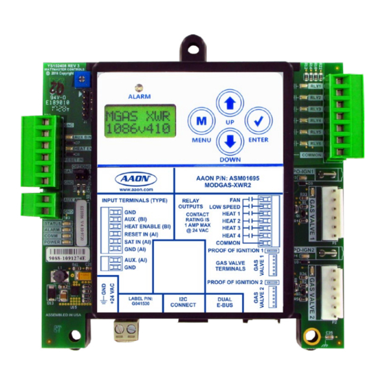
Communication LED COMM - This yellow LED will light up and blink when communications The MODGAS-XWR2 Controller is equipped with LEDs that can be are detected. If this LED never blinks, then there is no communication. used to verify operation and perform troubleshooting. There are LEDs for communication, operation modes, and diagnostic codes. - Page 30 TROUBLESHOOTING Troubleshooting Figure 16: MODGAS-XWR2 Controller LED Locations and Descriptions MODGAS-XWR2 Technical Guide...
- Page 31 Remove SAT and GND wiring from the MODGAS- Mechanical Failure: XWR2 and ohm sensor out (this may indicate open or • Check relay outputs on the MODGAS-XWR2 for 24 failed wiring). Refer to chart on pages 32-33 of this VAC output. guide for readings.
- Page 32 If the voltage is above 3.3 VDC, the sensor or wiring is “open.” If the voltage is less than 0.05 VDC, the sensor or wiring is shorted. Table 5: 0-3.3 V Temperature Sensor - Voltage & Resistance for Type III Sensors MODGAS-XWR2 Technical Guide...
- Page 33 25.6 9711 2.520 27.8 9302 2.465 27.8 8893 2.407 28.9 8514 2.352 30.0 8153 2.297 31.1 7805 2.242 32.2 7472 2.187 35.0 6716 2.055 Table 6: 0-5V Temperature Sensor - Voltage & Resistance for Type III Sensors MODGAS-XWR2 Technical Guide...
-
Page 34: Appendix A - Supply Air Temperature Sensor Installation
Mounting the Supply Air Temperature Sensor In Stand-Alone Mode, the SAT Sensor is connected to the MODGAS- XWR2 Controller. If, in Stand-Alone Mode, the MODGAS-XWR2 Controller is used in conjunction with a Stand-Alone MHGRV • The Supply Air Temperature (SAT) Sensor should be... - Page 35 MODGAS-XWR2 ONLY MODGAS-XWR2 & MHGRV-X STAND-ALONE Install Supply Air Install Sensor in MODGAS-XWR2 and daisy-chain Sensor in MODGAS-XWR2. it to the MHGRV-X. Set “SAT Options” Jumpers to “MODGAS X”. If connected to a MODGAS II Retrofit, Set “SAT Options” Jumpers to “MODGAS”.
-
Page 36: Appendix B - Modgas-Xwr2 Replacement Of The Modgas-Xwr
MODGAS-XWR and replug them into the MODGAS- XWR2 board. Disconnect power from the MODGAS-XWR Controller. Step 1: Wire the MODGAS-XWR2 relays according to the Step 6: Step 2: Set the SAT Options Jumper to the same settings as valve configuration you will be using. - Page 37 NOTES MODGAS-XWR2 Technical Guide...
- Page 38 PARTS: For replacement parts please contact your local AAON Representative. 2425 South Yukon Ave • Tulsa, OK • 74107-2728 Ph: (918) 583-2266 • Fax: (918) 583-6094 AAON P/N: V22330, Rev. 01C ® Printed in the USA • © January 2020 AAON • All Rights Reserved...
Need help?
Do you have a question about the MODGAS-XWR2 and is the answer not in the manual?
Questions and answers