Sign In
Upload
Download
Table of Contents
Contents
Add to my manuals
Delete from my manuals
Share
URL of this page:
HTML Link:
Bookmark this page
Add
Manual will be automatically added to "My Manuals"
Print this page
×
Bookmark added
×
Added to my manuals
Manuals
Brands
AAON Manuals
Control Unit
MODGAS-XWR2
Technical manual
AAON MODGAS-XWR2 Technical Manual
Hide thumbs
Also See for MODGAS-XWR2
:
Technical manual
(38 pages)
1
2
Table Of Contents
3
4
5
6
7
8
9
10
11
12
13
14
15
16
17
18
19
20
21
22
23
24
25
26
27
28
29
30
31
32
33
34
35
36
37
38
39
40
41
42
43
page
of
43
Go
/
43
Contents
Table of Contents
Troubleshooting
Bookmarks
Table of Contents
Table of Contents
Overview
General Information
Dimensions
Figure 1: MODGAS-XWR2 Module Dimensions
Wiring
Important Wiring Considerations
Table 1: Electrical and Environmental Requirements
Stand-Alone Wiring
One Modulating Valve, One Ignitor, One Stage (1V1IGN1S)
Figure 2: Stand-Alone Wiring - One Modulating Valve, One Ignitor, One Stage
Two Modulating Valves, Two Ignitors, Two Stages (2V2IGN2S)
Figure 3: Stand-Alone Wiring - Two Modulating Valves, Two Ignitors, Two Stages
Figure 4: Stand-Alone Wiring - Secondary Board 2V2IGN2S
Two Modulating Valves, One Ignitor, One Stage (2V1IGN1S)
Figure 5: Stand-Alone Wiring - Two Modulating Valves, One Ignitor, One Stage
Figure 6: Stand-Alone Wiring - Secondary Board 2V1IGN1S
Two Modulating Valves, Two Ignitors, One Stage (2V2IGN1S)
Figure 7: Stand-Alone Wiring - Two Modulating Valves, Two Ignitors, One Stage
12 Relay E-BUS Expansion Module
Figure 8: Stand-Alone Wiring - 12 Relay E-BUS Expansion Module
Communications Wiring
One Modulating Valve, One Ignitor, One Stage (1V1IGN1S)
Figure 9: Communications Wiring - One Modulating Valve, One Ignitor, One Stage
Two Modulating Valves, Two Ignitors, One Stage (2V2IGN1S)
Figure 10: Communications Wiring - One Modulating Valve, Two Ignitors, One Stage
Two Modulating Valves, Two Ignitors, Two Stages (2V2IGN2S)
Figure 11: Communications Wiring - Two Modulating Valves, Two Ignitors, Two Stages
Figure 12: Communications Wiring - Secondary Board 2V2IGN2S
Two Modulating Valves, One Ignitor, One Stage (2V1IGN1S)
Figure 13: Communications Wiring - Two Modulating Valves, One Ignitor, One Stage
Figure 14: Stand-Alone Wiring - Secondary Board 2V1IGN1S
Inputs and Outputs
Table 2: MODGAS-XWR2 Inputs and Outputs
Sequence of Operation
Operating Modes and Min Mode
Heating Mode
Valve Failure, Force Mode and Master Vs. Normal
Lcd Screens
Navigation Keys
Figure 15: LCD Display and Navigation Keys
Table 3: Navigation Key Functions
Table 4: Editing Key Functions
Main Screens Map
Main Screens
Alarms Menu and Slave Alarms
Setpoint Screens
Force Valves Screens
Protected and Configuration Screens
Configuration Screens
Troubleshooting
LED Diagnostics
Table 5: STATUS LED Blink Codes
Table 6: ALARM LED Blink Codes
Figure 16: MODGAS-XWR2 LED Locations and Descriptions
Alarms
SAT Sensor Testing
Table 7: 0-3V Temperature Sensor - Voltage and Resistance for Type III Sensors
Table 8: 0-5V Temperature Sensor - Voltage and Resistance for Type III Sensors
Appendix A: Sat Sensor
Installation
Figure 17: Supply Air Temperature Sensor Installation
SAT Sensor Wiring Guide and Jumper Settings
Table 9: SAT Wiring Conditions
Table 10: Stand-Alone Mode SAT OPTIONS Jumper Settings
Table 11: Communication Mode SAT OPTIONS Jumper Settings
Appendix B: Modgas-Xwr Replacement
MODGAS-XWR2 Replacement of MODGAS-XWR
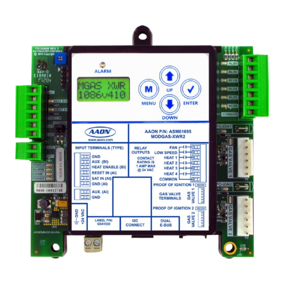
Figure 18: MODGAS-XWR2 Module
Advertisement
Quick Links
Download this manual
MODGAS-XWR2 Module
Technical Guide
Table of
Contents
Previous
Page
Next
Page
1
2
3
4
5
Advertisement
Table of Contents
Need help?
Do you have a question about the MODGAS-XWR2 and is the answer not in the manual?
Ask a question
Questions and answers
Related Manuals for AAON MODGAS-XWR2
Controller AAON MODGAS-XWR2 Technical Manual
(38 pages)
Control Unit AAON MODGAS-X Technical Manual
(38 pages)
Control Unit AAON MHGRVX-A2 Technical Manual
(35 pages)
Control Unit AAON MODGAS-XWR2-B Technical Manual
(44 pages)
Control Unit AAON HP2C2 Technical Manual
Two condenser head pressure ii module (17 pages)
Control Unit AAON RSMD-CM Technical Manual
Refrigerant system module for digital compressors with condenser fans with microchannel coils (43 pages)
Control Unit AAON SS1068 Quick Start Manual
Modular system manager sd (20 pages)
Control Unit AAON RSMZ Technical Manual
(40 pages)
Control Unit AAON RSMD2R Technical Manual
(42 pages)
Control Unit AAON RSMD Technical Manual
(42 pages)
Control Unit AAON RSMD Series Technical Manual
(37 pages)
Control Unit AAON RSMVQ2R Technical Manual
Refrigerant system module (36 pages)
Control Unit AAON RSMV ASM01686 Technical Manual
Refrigerant system module for vfd compressors (32 pages)
Control Unit AAON RSMVQ Technical Manual
(36 pages)
Control Unit AAON RSM-DEV1 Technical Manual
(40 pages)
This manual is also suitable for:
Asm01695
Table of Contents
Print
Rename the bookmark
Delete bookmark?
Delete from my manuals?
Login
Sign In
OR
Sign in with Facebook
Sign in with Google
Upload manual
Upload from disk
Upload from URL


Need help?
Do you have a question about the MODGAS-XWR2 and is the answer not in the manual?
Questions and answers