RGBlink mini+ User Manual
Hide thumbs
Also See for mini+:
- Installation precautions (9 pages) ,
- Quick start manual (35 pages) ,
- Product faqs (9 pages)
Table of Contents
Advertisement
Advertisement
Table of Contents

Related Manuals for RGBlink mini+


Summary of Contents for RGBlink mini+
- Page 1 User Manual Article NO: RGB-RD-UM-mini+ E000 Version NO: V1.0...
-
Page 2: Table Of Contents
Content Declarations..............................3 FCC/Warranty............................3 Operators Safety Summary.........................4 Installation Safety Summary....................... 4 Chapter 1 Your Product .......................... 6 1.1 In the Box............................6 1.2 Product Overview........................... 7 1.3 Dimension............................10 Chapter 2 Install Your Product......................11 2.1 Plug in Power..........................11 2.2 Turn on Your mini+........................11 2.3 Input HDMI Signal Source...................... -
Page 3: Declarations
30 days after the transfer of risks. In the event of justified notice of compliant, RGBlink can repair the fault or provide a replacement at its own discretion within an appropriate period. If this measure proves to be impossible or unsuccessful, the purchaser can demand a reduction in the purchase price or cancellation of the contract. -
Page 4: Operators Safety Summary
Operators Safety Summary The general safety information in this summary is for operating personnel. Do Not Remove Covers or Panels There are no user-serviceable parts within the unit. Removal of the top cover will expose dangerous voltages. To avoid personal injury, do not remove the top cover. Do not operate the unit without the cover installed. - Page 5 Unpacking and Inspection Before opening product shipping box, inspect it for damage. If you find any damage, notify the shipping carrier immediately for all claims adjustments. As you open the box, compare its contents against the packing slip. If you find any shortages, contact your sales representative. Once you have removed all the components from their packaging and checked that all the listed components are present, visually inspect the system to ensure there was no damage during shipping.
-
Page 6: Chapter 1 Your Product
Chapter 1 Your Product 1.1 In the Box Power Adapter USB3.0 Cable Note: Power Adapter supplied as standard according to destination market. For computers/phones/pads without HDMI port but with Type C interface, you can convert Type C to HDMI.Be sure that the Type C interface shall meet the USB 3.1 standard. mini+ User Manual... -
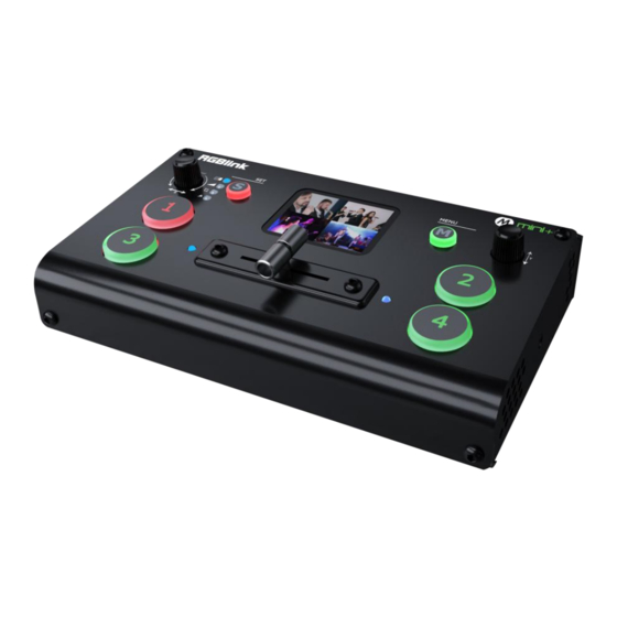
Page 7: Product Overview
1.2 Product Overview mini+, as a pocket-sized push-stream switcher, supports real-time monitoring, special effects switching,live streaming, audio insertion, independent input format conversion,PTZ camera control based on VISCA protocol, Chroma key, LOGO overlay and other functions. mini+ is able to control 8 PTZ cameras at the same time and do operations of Zoom In/Out. - Page 8 1.2.2 Front Panel 1. Turn to adjust volume of PGM VOLUME/X 2. Control camera left-right spinning when it is in PTZ setting Function selection button to select 1. Transition Effect ( 2. Switch Mode(MODE:CUT or T-Bar), 3. PIP( 4. FX( , enter PTZ camera setting) M(menu) Menu and back button...
- Page 9 1.2.3 Interface Panel HDMI IN 4 HDMI Inputs, connect to input source from HD camera or PC HDMI OUT 1 HDMI Output port, connect to display to show Preview (6 pictures) or PGM. DC 12V 1 DC Jack for power input, connect to 12V/4A power adapter. Communication port to link dedicated software for control USB3.0 output, capture signal via third party streaming software and push to live broadcasting websites...
-
Page 10: Dimension
1.3 Dimension Following is the dimension of mini+ for your reference: 180mm×113mm×49mm mini+ User Manual... -
Page 11: Chapter 2 Install Your Product
Chapter 2 Install Your Product 2.1 Plug in Power RGBlink mini+ is packaged with a 12V power link cable and two standard power plugs for British and Australian standards. When linking the power supply, please check the power supply standard used in your country/region. If you are... -
Page 12: Connecting Hdmi Output
Note: The HDMI cable is not included in the mini+ package and needs to be purchased separately. Some camcorders use a mini HDMI port, you need to buy a mini HDMI-HDMI cable separately when you use these camcorders. 2.4 Connect HDMI Output In the mini+, you can choose to use HDMI output as the pre-monitoring interface to achieve 16:9 6-picture split pre-monitoring, and we also provide a preset function. -
Page 13: Connecting Microphone And External Monitoring Devices
Note:If your computer only has a Type-C port, you can use a USB-A to Type-C cable to transmit the webcam signal. Please note that the Type-C cable you choose needs to support data transmission. The signal is recognized in Windows system as「RGBlink 」. mini+... -
Page 14: Connect Computer And Mini
2.7 Connect Computer and mini+ Software control:connect computer and mini+ with CAT6 cable Record and Stream:connect mini+’s USB-A and mini+’s USB 3.0 port with USB3.0 cable (Note:the color of USB3.0 port is blue) Note:The IP address of the mini+ must be in the same WLAN segment as the computer. mini+ User Manual... -
Page 15: Chapter 3 Use Your Product
Chapter 3 Use Your Product 3.1 Menu Main Menu After mini+ is powered on, push button M to enter the main menu. Main Menu include:Input, HDMI, USB 3.0. Audio, Logo Overlay, Ip Setting, Language, Reset 3.1.1 Input Push「M」button(MENU) to enter main menu The input menu displays the information of the and select first menu item<INPUT>,push「Y」... - Page 16 3.1.2 HDMI 1.Push MENU and select the second menu item 2.rotate 「Y」 knob to select PVW output and <HDMI> PGM output for HDMI. 「Y」 Output:PVW or PGM Push knob to enter <HDMI> menu. Format:1920×1080@60 3.1.3 USB3.0 「Y」 「 Y 」 2.rotate knob to select PVW output and 1.Push MENU, rotate and push...
- Page 17 3.1.5 LOGO Overlay 2.Rotate 「Y」 knob and select ON/OFF 1.Push MENU,rotate and push 「Y」 knob to ENABLE and set the position of LOGO enter the fifth menu item<LOGO OVERLAY> Note: If It is your first time to use the logo overlay function, please refer to 3.4.2 Using XPOSE mini first. 3.1.6 IP Setting Push MENU,rotate and push 「Y」...
- Page 18 3.1.7 Language 1.Push MENU and rotate and push「Y」knob to 2.Rotate and push「Y」knob to select enter the seventh menu item<LANGUAGE> Chinese and English. 3.1.8 Factory Reset 1.Push MENU and rotate and push「Y」knob 2.Rotate and push「Y」knob to select YES or to enter the eighth menu item<RESET> 、...
-
Page 19: S Button
3.1.9 INFO Push MENU and rotate and push「Y」 knob to enter the ninth menu item<INFO> INFO shows Device SN,IP address,MAC address,MAC address,MCU version,Video version. 3.2 S Button When you want to personalize your live show, you can use the mini+'s 14 built-in switching effects and control the timing of the switch via T-BAR. - Page 20 4. Push S button four times to enter PTZ camera control menu and the LED indicator beside will light up; Each time the menu is opened, the corresponding indicator light will be on, and then rotate the PUSH knob (" Y ") to select and confirm.
- Page 21 3.2.2 MODE Push S button twice to enter <MODE>menu,and rotate 「Y」knob to select FAST or T-BAR After selecting Quick Cut, you need to select the switching time: from 0.5s to 5.0s. The steps are as follows. 1.Press the "S" button twice to enter the Mode include Fast and T-Bar mode interface.
- Page 22 3.2.3 PIP Push S button three times to enter <PIP> menu and select PIP mode(9 PIP modes)The steps are as follows: 1. Select the signal you want for background. 2. Push "S" button three times to enter PIP (When the letter is A, it means background setting page.
- Page 23 How to Enter PIP Menu Quickly S button has memory function.When the TFT screen returns to preview mode, press S button to directly enter PIP menu if you use it last time. If you want to enter other menus, continue to press the "S" button. 3.2.4 PTZ Camera Setting mini+ can control cameras which supports VISCA protocol.mini+ allows users to control camera to move,zoom and focus.Meanwhile, mini + also saves camera position and zoom information for quick retrieval the next time...
-
Page 24: Switch Source
Note:The IP address of mini + and PTZ should be in the same network segment. 4.Push MENU and back to <CONTROL> ,then 3.Rotate 「 Y 」 knob and turn on you can control PTZ camera’s position,zoom corresponding ENABLE and focus. mini+ can control up to 8 cameras. - Page 25 In T-BAR Mode: Press a green button to set the source as the PVW, the source button will blink green. Slide the T-BAR to switch/mix from the current PGM source to the PVW source.Any MIX transition effect will be applied as the T-BAR is moved. Once the T-BAR has been fully transitioned, the indicator lights on sources buttons that are PGM and PVW will be swapped.
-
Page 26: Chapter 4 Streaming
Click video capture device to open up setting page Choose :RGBlink USB 3.0 Capture 5. Choose Video Format YUY2 Note:If there is no video format YUY 2 after setting above, check the USB 3.0 port connection. Make sure it is linked to USB 3.0port on PC by USB 3.0 cable. - Page 27 Audio Setting When there is no audio playing first check the video source see if the it is set in default value and then check the audio setting on OBS. 1. Set Default for the audio source. 2. Audio setting on OBS. Choose Audio, click Setting and choose audio device (Mic/Auxiliary Audio Device) Synchronize Video with External Audio...
- Page 28 2.Right click the Video Capture Device in Source and choose Filter 3. Click “+”under Audio/Video Filters and choose Video Delay (Async) 4.You can custom the filter name in the pop-up window. Click OK to confirm the filter name. 5.Input delay value in ms, the value need to adjusted until the video and audio is synchronous.
-
Page 29: Vmix Streaming
Streaming Setting 1. Find the RTMP URL and Stream Key provided by streaming broadcast website. 2. Copy URL and Stream Key 3. Back to OBS, click Setting in the lower right corner and click “Stream”. Choose Stream Type as “Streaming Service”... - Page 30 Note: vMix does not support automatic recognition of the output resolution of mini+. Every time the output resolution of mini+ is modified, the picture on vMix will pause. The user needs to re-select RGBlink USB3.0 Capture and manually input the current output resolution of mini+.
-
Page 31: Chapter 5 Xpose Mini Operation
Chapter 5 XPOSE mini Operation XPOSE mini is a software that allows you to control your mini+, RGBlink is available for all platforms including Android, iOS, MacOS, Windows. You can either connect the mini+ directly to your computer via the LAN port provided by the mini+, or link the mini+ to your router and the computer to the Wi-Fi emitted by your wireless router. - Page 32 1. Open the “Network and Sharing Center”; 2. Click on "Internet"; 3. Access to Properties may require administrator privileges; 4. Under "This connection uses the following items", find "Internet Protocol version 4 (TCP/IPv4)"; 5. Select "Use the following IP address" and change the IP address to the same network segment as mini+, eg: mini+'s IP address is 192.168.0.99, then the computer's IP address can be set to 192.168.0.1-255.
- Page 33 1. Open XPOSE mini and click on the icon in the upper right corner 2. Enter the IP address of the currently connected mini+. 5.1.3 Connect Wirelessly with Your Router The mini+ provides wireless control, so you can control it from a greater distance when the mini+ is not in your immediate vicinity.
-
Page 34: Using Xpose Mini
3. Enter the IP settings sub-menu 4. Turn on the DHCP switch. 5. Computer connects to Wi-Fi from the router. 6. Open XPOSE mini search Note:The Android and IOS versions can only connect wirelessly. Regardless of whether you are using wireless or wired, you need to make sure that the IP addresses are on the same network segment and that they do not conflict. - Page 35 After searching, all available mini+ devices in the sub-net can be found, up to 128 devices can found if there are. Select the desired device by SN and IP and enter the management interface. The software interface is a simulation of operation panel on real mini+ device. For example, clicking Button M can open up menu as on the device.
- Page 36 Following sections are dedicated to the additional features of XPOSE mini. 5.2.2 Live Streaming Device Capture:choose RGBlink USB3.0 Capture H.265: When it is ON, users can watch 4 inputs streaming back on XPOSE software. Import the related OBS application if users need to do live streaming, click Relate to confirm.
- Page 37 2. Select the mode of the test pattern. 3.Adjust color. 5.2.4 Password Protection In order to solve the problem of control conflicts caused by different devices controlling the same mini+ in the same LAN, XPOSE mini provides a password protection function, as an administrator, you can set a password for the device controlling XPOSE mini, and when you control the interface again, you need to...
- Page 38 5.2.5 T-Bar Calibration If the T-Bar is not in the correct position, no other operation is possible. t-Bar correction is available in XPOSE mini. The steps are as follow: 1. Turn on the T-Bar Calibration switch. 2. Push the T-Bar to the far right on the mini+. 3.
- Page 39 2.adjust color in the range of MAX, MIN and MARGIN. You can click in the MAX MIN MARGIN data input box to achieve a more precise keying effect. 3.Chroma key effect on mini+ as shown in the figure. Note: When using chroma key, make sure that the layer you want to edit is on the top layer, which is the B layer in the PIP setting, otherwise you may not see the chromakey effect.
- Page 40 2. Set both old IP and new IP to the camera IP address you want to control,the corresponding communication port to 1259 on mini+, configuration path: M(Menu) → FX → PTZ Camera Setting Port on the control software of mini+. 3.
-
Page 41: Upgrade
5.2.8 Logo Overlay If it is your first time to use Logo Over lay, please connect mini+ to your computer, and make sure that IP address of both are in the same network segment. 1. Select a picture as the Logo. 2. - Page 42 2.Upgrade 2.1 Power on the device connect LAN ports between PC and device by Cat6 cable; 2.2xEnsure that your computer is on the same network as the mini+. The default IP address of mini+ is 192.168.0.99, in which case your computers IP address should be in the range 192.168.0.xxx (xxx cannot b e the same as mini+ or other device on the network) to enable connection between the mini+ and your computer.
- Page 43 If the XTOOL app has been installed previously, use the Modify option to complete the setup. XTOOL is a universal updater application for RGBlink products, as such has a number of features in support of the full range of RGBlink devices that are not utilised for mini+ updates in this guide.
- Page 44 Upgrade Step 1. After Connection, XTOOL automatically matches the upgrade program, and click the "upgrade" button to upgrade automatically. Step 2. Monitor the progress DO NOT DISCONNECT OR POWER DOWN while updating Finish Step 1. Close XTOOL Step 2. Disconnect mini+ Step 3.
-
Page 45: Chapter 6 Ordering Codes
Chapter 6 Ordering Codes 6.1 Product Code 230-0001-02-0 mini+ mini+ User Manual... -
Page 46: Chapter 7 Support
Chapter 7 Support 7.1 Contact US mini+ User Manual... -
Page 47: Chapter 8 Appendix
Chapter 8 Appendix 8.1 Specification Connectors Input HDMI In 4×HDMI-A Output HDMI Out 1×HDMI-A USB 3.0 1×USB TypeA 1×3.5mm Stereo Jack Audio 1×3.5mm Stereo Jack Communication LAN 1×RJ45 Power 1×DC Power Jack Performance Input HDMI Resolutions SMPTE 720p@50/60 |1080i@50 | 1080p@23/24/30/50/60 1024×768@60 | 1280 ×... -
Page 48: Terms & Definitions
8.2 Terms & Definitions ●RCA: Connector used primarily in consumer AV equipment for both audio and video. The RCA connector was developed by the Radio Corporation of America. ●BNC: Stands for Bayonet Neill-Concelman. A cable connector used extensively in television (named for its inventors). A cylindrical bayonet connector that operates with a twist-locking motion . - Page 49 resolution 1920 × 1080 at 120 Hz or 2560 × 1440 at 60 Hz). It added support for 10 bpc, 12 bpc, and 16 bpc color depth (30, 36, and 48 bit/px), called deep color. ●HDMI 1.4: Released on June 5, 2009, added support for 4096 × 2160 at 24 Hz, 3840 × 2160 at 24, 25, and 30 Hz, and 1920 × 1080 at 120 Hz.
- Page 50 of optical fiber connectors are SC, FC, LC,ST. ●SC: (Subscriber Connector), also known as the square connector was also created by the Japanese company – Nippon Telegraph and Telephone. SC is a push-pull coupling type of connector and has a 2.5mm diameter. Nowadays, it is used mostly in single mode fiber optic patch cords, analog, GBIC, and CATV.
- Page 51 ●PAL: Phase Alternate Line. A television standard in which the phase of the colour carrier is alternated from line to line. It takes four full images (8 fields) for the colour-to-horizontalimages (8 fields) for the colour-to-horizontal phase relationship to return to the reference point. This alternation helps cancel out phase errors. For this reason, the hue control is not needed on a PAL TV set.
- Page 52 audio/video digital compression and Transmission. ●H.264: Also known as AVC (Advanced Video Coding) or MPEG-4i is a common video compression standard. H.264 was standardized by the ITU-T Video Coding Experts Group (VCEG) together with the ISO/IEC JTC1 Moving Picture Experts Group (MPEG).
- Page 53 ●Gamma: The light output of a CRT is not linear with respect to the voltage input. The difference between what you should have and what is actually output is known as gamma. ●Frame: In interlaced video, a frame is one complete image.A video frame is made up of two fields, or two sets of interlaced lines.
-
Page 54: Revision History
0000# Release Sylvia All information herein is Xiamen RGBlink Science & Technology Co Ltd. excepting noted. is a registered trademark of Xiamen RGBlink Science & Technology Co Ltd. While all efforts are made for accuracy at time of printing, we reserve the right to alter otherwise make change without notice.
Need help?
Do you have a question about the mini+ and is the answer not in the manual?
Questions and answers