Table of Contents
Advertisement
Quick Links
Advertisement
Table of Contents

Related Manuals for Ursalink EM500-UDL


Summary of Contents for Ursalink EM500-UDL
- Page 2 Please clarify your application environment before deployment so that the device can function well. The device is not intended to be used as a reference sensor, and Ursalink will not should responsibility for any damage which may result from inaccurate readings.
-
Page 3: Table Of Contents
6.1.2 Basic Settings-ABP....................20 6.1.3 Channel Settings.......................21 6.2 Device Settings........................23 6.2.1 General........................23 6.2.2 Data Calibration......................23 6.2.3 Threshold........................24 7.Sensor Management via Ursalink Cloud..................24 7.1 Ursalink Cloud Registration....................24 7.2 Add a Ursalink LoRaWAN Gateway..................25 7.3 Add EM500-UDL to Cloud....................26... -
Page 4: Overview
Sensor data are transmitted in real-time using standard LoRaWAN protocol. LoRaWAN enables encrypted radio transmissions over long distance while consuming very little power. The user can obtain sensor data and view the trend of data change through Ursalink Cloud or thr ough the user's own Network Server. -
Page 5: Dimensions(Mm)
EM500-UDL User Guide Battery Life 6 year (10 min interval, SF12) >10 year (10 min interval, SF7) Operating Temperature -20°C to +70°C Relative Humidity 0% to 100% (non-condensing) Dimension 156.1 × 71 × 69.5 mm Mounting Pole, wall, DIN rail 1.4 Dimensions(mm) -
Page 6: Product Overview
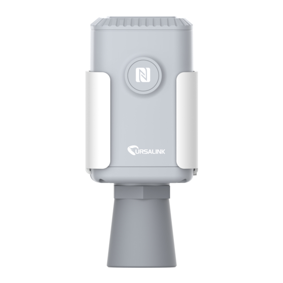
EM500-UDL User Guide If any of the above items is missing or damaged, please contact your Ursalink sales representative. 2.2 Product Overview Front View: ①LoRa Antenna (Internal) ②NFC Area ③Ultrasonic Horn Back View: ④Battery (Internal) ⑤Wall Mounting Holes ⑥Pole Mounting Holes Sensor Installation 3.1 Installation Location... -
Page 7: Wall Mounting
EM500-UDL User Guide 3.2 Wall Mounting 1. Attach the mounting bracket to the wall and drill. (Around 16mm) Note: The connecting line of two holes must be a horizon line. 2. Drive two screws into wall at the marks using screw driver. -
Page 8: Din Rail Mounting
DIN rail on the mounting bracket. It is necessary to choose a standard bracket. 4. Turn ON/OFF the Sensor EM500-UDL can be turned ON/OFF via smartphone or computer with NFC (Near Field Communication) or button. Select one of following methods to turn on/off the sensor. - Page 9 EM500-UDL User Guide 4. Device information will be shown on the APP. 5. Switch the button of Device Status to turn on or off the device. 6. Enter the correct password (default password: 123456) and wait a few seconds until APP shows “Operate Successful!”.
-
Page 10: Turn On/Off Via Pc Software
EM500-UDL User Guide 4.2 Turn ON/OFF via PC Software 1. Download Ursalink configuration software “Toolbox” and open the software. 2. Connect NFC reader to computer and attach the device to NFC reader. 3. Select type as NFC and serial port of NFC reader, then click “save”. -
Page 11: Turn On/Off Via Button
7. Enter password (default password:123456) and press Enter key to change device status. 4.3 Turn ON/OFF via Button 1. Remove screws on the bottom of EM500-UDL and take off the upper enclosure. 2. Find the button beside the battery. 3. Press the button until LED blinks to turn on or off the device. (about 3 seconds) Press the button until LED blinks rapidly to reset the device to factory default. -
Page 12: Read Configuration
EM500-UDL User Guide 5.1.1 Read Configuration 1. Open APP “Toolbox” and click “Read” to read current information of device. 1. Attach the smartphone with NFC area to the device until the APP shows “Read Successful!”. Note: Failing to read can be caused by long distance, wrong location, or rapid movement. -
Page 13: Template Settings
EM500-UDL User Guide 3. Enter password (default password: 123456). 4. Attach the smartphone with NFC area to the device and wait a few seconds until APP shows “Write Successful!”. The device will automatically re-join the network if LoRaWAN paramters are changed. - Page 14 EM500-UDL User Guide 2. Attach the smartphone with NFC area to another device. 3. Select the template file from Toolbox APP and click “Write”. 4. Enter password of this device and keep the two devices close until the APP shows “Write successful!”.
-
Page 15: Configuration Via Pc
EM500-UDL User Guide 5.2 Configuration via PC Make sure “Toolbox” is downloaded on your computer. 5.2.1 Read Configuration 1. Open software “Toolbox” and click “Read” to read current information of device. 3. Attach the device to the NFC reader until Toolbox shows “success”. -
Page 16: Upgrade
EM500-UDL User Guide 3.Press Enter key to write and attach the device close to NFC reader until “Write” button disappear. The device will automatically re-join the network if LoRaWAN paramters are changed. Note: Keep the two devices close and don’t move them in order that you can get the best connectivity as possible when writing data via NFC. -
Page 17: Template And Reset
EM500-UDL User Guide 5.2.3.2 FOTA 1. Make sure your computer can access the Internet. 2. Click “Check for Updates” to search for the latest firmware via computer Internet and upgrade. Note: Keep the two devices close and don’t move them in order that you can get the best connectivity as possible when upgrading. - Page 18 EM500-UDL User Guide 3. Click “Browse” to select the correct template from computer. 4. Click “Import” to import the template to the device. 6.2.4.2 Reset Click the “Reset” to reset the setting to factory default.
-
Page 19: Sensor Parameters (For App And Pc)
6.Sensor Parameters (for App and PC) 6.1 LoRa WAN Settings 6.1.1 Basic Settings-OTAA Location: Ursalink ToolBox(PC): LoRaWAN Settings → Basic Ursalink ToolBox(APP): Device → Settings → LoRaWAN Settings Basic Settings-OTAA Item Description Default Enter the application EUI.The Network Server receives... -
Page 20: Basic Settings-Abp
Network Server will not adjust the datarate of the device. 6.1.2 Basic Settings-ABP Location: Ursalink ToolBox(PC): LoRaWAN Settings → Basic Ursalink ToolBox(APP): Device → Settings → LoRaWAN Setting Basic Settings-ABP Item Description Default Enter the application EUI.The Network Server receives... -
Page 21: Channel Settings
Network Server will not adjust the datarate of the device. 6.1.3 Channel Settings Location: Ursalink ToolBox(PC): LoRaWAN Settings → Channel Ursalink ToolBox(APP): Device → Settings → LoRaWAN Settings Note: Make sure the LoRa channel configuration of EM500-UDL matches the LoRaWAN gateway. - Page 22 EM500-UDL User Guide LoRa frequency configuration is as follows if the sensor LoRa frequency is one of EU433/EU868/RU864/IN865/AS923/KR920: LoRa frequency configuration is as follows if the sensor LoRa frequency is one of CN470/US915/AU915: Enter the index of the channel to be enabled in the input box, separated by commas.
-
Page 23: Device Settings
6.2.2 Data Calibration Location: Ursalink ToolBox(PC): Device Settings → Data Calibration Settings Ursalink ToolBox(APP): Device → Settings → Data Calibration Settings Note: It is recommended to do the calibration before using the device. Data Calibration Settings Item... -
Page 24: Threshold
5mins. 7.Sensor Management via Ursalink Cloud Ursalink cloud is a comprehensive platform that provides multiple services including device remote management and data visualization with the easiest operation procedures. 7.1 Ursalink Cloud Registration Register and log in Ursalink Cloud. -
Page 25: Add A Ursalink Lorawan Gateway
EM500-UDL User Guide 7.2 Add a Ursalink LoRaWAN Gateway 1. Enable “Ursalink” type network server and “Ursalink Cloud” mode in gateway web GUI. Note: Ensure gateway has accessed the Internet. -
Page 26: Add Em500-Udl To Cloud
2.Go to “My Devices->Gateway” of Ursalink Cloud and click “Add” to add gateway to Ursalink Cloud via SN. 3.Check if gateway is online in Ursalink Cloud. 7.3 Add EM500-UDL to Cloud 1. Go to “Device->My Devices” and click “Add Device”. Fill in the SN of EM500-UDL and select associated gateway. - Page 27 EM500-UDL User Guide 2. After EM500-UDL is connected to Ursalink Cloud, Click or “History Data” to check the data on Ursalink cloud. 3.Go to “Dashboard” page to add dashboard.
- Page 28 EM500-UDL User Guide FCC Caution: Any Changes or modifications not expressly approved by the party responsible for compliance could void the user's authority to operate the equipment. This device complies with part 15 of the FCC Rules. Operation is subject to the following two conditions: (1) This device may not cause harmful interference, and (2) this device must accept any interference received, including interference that may cause undesired operation.
Need help?
Do you have a question about the EM500-UDL and is the answer not in the manual?
Questions and answers