Table of Contents
Advertisement
Quick Links
Advertisement
Table of Contents

Subscribe to Our Youtube Channel
Related Manuals for Ursalink EM500-UDL


Summary of Contents for Ursalink EM500-UDL
- Page 2 Please clarify your application environment before deployment so that the device can function well. The device is not intended to be used as a reference sensor, and Ursalink will not should responsibility for any damage which may result from inaccurate readings.
-
Page 3: Table Of Contents
6.3 Pole Mounting........................18 6.4 DIN Rail Mounting....................... 18 7. Payload Format..........................18 7.Sensor Management via Ursalink Cloud..................19 7.1 Ursalink Cloud Registration....................19 7.2 Add a Ursalink LoRaWAN Gateway..................20 7.3 Add EM500-UDL to Cloud....................21 Appendix............................22 Default LoRaWAN Parameters....................22 Default Uplink Channels......................22... -
Page 4: Overview
Sensor data are transmitted in real-time using standard LoRaWAN protocol. LoRaWAN enables encrypted radio transmissions over long distance while consuming very little power. The user can obtain sensor data and view the trend of data change through Ursalink Cloud or thr ough the user's own Network Server. -
Page 5: Hardware Introduction
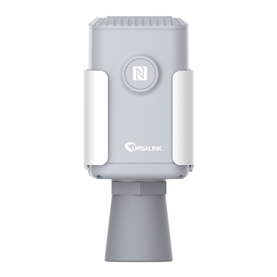
1 × Warranty Card 1 × Quick Guide Screws Clamp 1 × DIN Rail (Optional) If any of the above items is missing or damaged, please contact your Ursalink sales representative. 2.2 Product Overview Front View: ①LoRa Antenna (Internal) ②NFC Area... -
Page 6: Dimensions
EM500-UDL User Guide Back View: ④Battery (Internal) ⑤Wall Mounting Holes ⑥Pole Mounting Holes 2.3 Dimensions(mm) Insulating Sheet Disassembly 1. Take off the mounting bracket, remove the lid and screws on the bottom of the device, and then take off the enclosure cover. -
Page 7: Turn On/Off And Reset (Power Button)
Chapter 4 to check if EM500 can be turned on via power button. 4. Turn ON/OFF and Reset (Power Button) The LED indicator is inside the device. EM500-UDL can also be turned on/off and reset via Mobile APP or Toolbox. Function... -
Page 8: Configuration Via Smartphone App
EM500-UDL User Guide 5.1 Configuration via Smartphone APP Preparation: Smartphone (NFC supported) Toolbox APP: download and install from Google Play or Apple Store. 5.1.1 Read/Write Configuration via NFC 1. Enable NFC on the smartphone and open “Toolbox” APP. -
Page 9: Template Configuration
EM500-UDL User Guide 5.1.2 Template Configuration Template settings are used for easy and quick device configuration in bulk. Note: Template function works only for sensors with the same model and LoRa frequency band. 1. Go to “Template” page on the APP and save current settings as a template. - Page 10 EM500-UDL User Guide 4. Enter password of this device and keep the two devices close until the APP shows a successful prompt. 5. Slide the template item to the left to edit or delete the template.
-
Page 11: Configuration Via Pc
2. Select type as “General” and click password to log in Toolbox. (Default password: 123456) NFC Connection 1. Connect the NFC reader to computer, then attach the EM500-UDL to NFC area of the reader. 2. Select type as “NFC” and serial port as NFC reader port on Toolbox. -
Page 12: Basic Configuration
EM500-UDL User Guide 5.2.2 Basic Configuration 1. Click “Read” to read current data of the sensor. 2. When you perform one of the following operations, enter the password and wait a few seconds until toolbox shows a successful prompt. (Password is not needed if you connect it via... -
Page 13: Template And Reset
EM500-UDL User Guide 5.2.3 Template and Reset 5.2.3.1 Template Configuration Note: Template function works only for sensors with the same model and LoRa frequency band. 1. Go to “Maintenance -> Template and Reset” page in Toolbox. 2. Click “Export” to save the current settings as a template. -
Page 14: Upgrade
Note: If NFC connection is selected, please keep the two devices close and don’t move them in order to get the best connectivity as possible when upgrading. 5.3 Configuration Examples 5.3.1 LoRaWAN Channel Settings The configuration of LoRaWAN channel of EM500-UDL must match the LoRaWAN gateway’s. Refer to Appendix to check default channel settings of EM500-UDL. -
Page 15: Data Calibration Settings
EM500-UDL User Guide Mobile APP Configuration: Open Toolbox APP and go to “Device ->Setting -> LoRaWAN Settings”to change the frequency and channels. Software Configuration: Log in Toolbox and go to “LoRaWAN Settings -> Channel” to change frequency and channels. Note: If frequency is one of CN470/AU915/US915, you can enter the index of the channel that you want to enable in the input box, making them separated by commas. -
Page 16: Alarm Settings
Log in Toolbox and go to “Device Settings -> Basic -> Calibration Settings” to enable the calibration and type the calibration value. 5.3.3 Alarm Settings EM500-UDL will upload the current data instantly after the threshold is triggered. Mobile APP Configuration: Open Toolbox APP and go to “Device -> Setting -> Threshold Settings”to enable the threshold settings and input the threshold. -
Page 17: Sensor Installation
6.1 Installation Location When installing EM500-UDL, please take in mind: Ensure the location of EM500-UDL is within the communication range of LoRaWAN gateway. Device must sit in a vertical position on top of the object and be fitted such that it has a ... -
Page 18: Pole Mounting
EM500-UDL User Guide 6.3 Pole Mounting 1. Loosen the hose clamp by turning the locking mechanism counter-clockwise. 2. Straighten out the hose clamp and slide it through the rectangular holes in the mounting bracket, wrap the hose clamp around the pole. -
Page 19: Sensor Management Via Ursalink Cloud
03(Set Reporting Interval) b0 04 => 04 b0 = 1200 7.Sensor Management via Ursalink Cloud Ursalink cloud is a comprehensive platform that provides multiple services including device remote management and data visualization with the easiest operation procedures. 7.1 Ursalink Cloud Registration Register and log in Ursalink Cloud. -
Page 20: Add A Ursalink Lorawan Gateway
1. Enable “Ursalink” type network server and “Ursalink Cloud” mode in gateway web GUI. Note: Ensure gateway has accessed the Internet. 2.Go to “My Devices->Gateway” of Ursalink Cloud and click “Add” to add gateway to Ursalink Cloud via SN. 3.Check if gateway is online in Ursalink Cloud. -
Page 21: Add Em500-Udl To Cloud
EM500-UDL User Guide 7.3 Add EM500-UDL to Cloud 1. Go to “Device->My Devices” and click “Add Device”. Fill in the SN of EM500-UDL and select associated gateway. 1. After EM500-UDL is connected to Ursalink Cloud, Click or “History Data” to check the data on Ursalink cloud. -
Page 22: Appendix
EM500-UDL User Guide Appendix Default LoRaWAN Parameters 24E124 + 2 to 11 digits of SN DevEUI e.g. SN = 61 26 A1 01 84 96 00 41 Then Device EUI = 24E124126A101849 AppEUI 24E124C0002A0001 Appport 0x55 NetID 0x010203 The 5...
Need help?
Do you have a question about the EM500-UDL and is the answer not in the manual?
Questions and answers