Table of Contents
Advertisement
Quick Links
Advertisement
Table of Contents

Related Manuals for Ursalink EM500-PT100


Summary of Contents for Ursalink EM500-PT100
- Page 2 Please clarify your application environment before deployment, in case the device can function well. The device is not intended to be used as a reference sensor, and Ursalink will not should responsibility for any damage which may result from inaccurate readings.
-
Page 3: Table Of Contents
6.2 Pole Mounting........................17 6.3 DIN Rail Mounting....................... 18 7. Payload Format..........................18 8.Sensor Management via Ursalink Cloud..................19 8.1 Ursalink Cloud Registration....................19 8.2 Add a Ursalink LoRaWAN Gateway..................19 8.3 Add EM500-PT100 to Cloud....................20 Appendix............................22 Default LoRaWAN Parameters....................22 Default Uplink Channels......................22... -
Page 4: Overview
Sensor data are transmitted in real-time using standard LoRaWAN protocol. LoRaWAN enables encrypted radio transmissions over long distance while consuming very little power. The user can obtain sensor data and view the trend of data change through Ursalink Cloud or thr ough the user's own Network Server. -
Page 5: Hardware Introduction
2 × Mounting 1 × Hose 1 × Warranty Card 1 × Quick Guide (Include cable and probe) Screws Clamp 1 × DIN Rail (Optional) If any of the above items is missing or damaged, please contact your Ursalink sales representative. -
Page 6: Product Overview
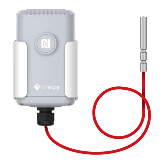
EM500-PT100 User Guide 2.2 Product Overview Front View: ①LoRa Antenna (Internal) ②NFC Area ③Water-proof Connector Back View: ④Battery (Internal) ⑤Wall Mounting Holes ⑥Pole Mounting Holes 2.3 Dimensions(mm) 3. Assembly and Preparation 3.1 Sensor Assembly Follow below to connect PT100 sensor cable to EM500 device if they are separated. -
Page 7: Insulating Sheet Disassembly
EM500-PT100 User Guide 2. Pass the cable through the cap, rubber seal 1. Take off the mounting bracket, remove the cap, and enclosure cover. rubber seal and the screws on the bottom of the device, and then take off the enclosure cover. -
Page 8: Turn On/Off And Reset (Power Button)
Chapter 4 to check if EM500 can be turned on via power button. 4. Turn ON/OFF and Reset (Power Button) The LED indicator is inside the device. EM500-PT100 can also be turned on/off and reset via Mobile APP or Toolbox. Function... -
Page 9: Read/Write Configuration Via Nfc
EM500-PT100 User Guide 5.1.1 Read/Write Configuration via NFC 1. Enable NFC on the smartphone and open “Toolbox” APP. 2. Attach the smartphone with NFC area to the device to read basic information. Note: Ensure your smartphone NFC area and it is recommended to take off phone case before using NFC. -
Page 10: Template Configuration
EM500-PT100 User Guide 5.1.2 Template Configuration Template settings are used for easy and quick device configuration in bulk. Note: Template function works only for sensors with the same model and LoRa frequency band. 1. Go to “Template” page on the APP and save current settings as a template. -
Page 11: Configuration Via Pc
EM500-PT100 User Guide 4. Enter password of this device and keep the two devices close until the APP shows a successful prompt. 5. Slide the template item to the left to edit or delete the template. 5.2 Configuration via PC... -
Page 12: Log In The Toolbox
2. Select type as “General” and click password to log in Toolbox. (Default password: 123456) NFC Connection 1. Connect the NFC reader to computer, then attach the EM500-PT100 to NFC area of the reader. 2. Select type as “NFC” and serial port as NFC reader port on Toolbox. -
Page 13: Basic Configuration
EM500-PT100 User Guide 5.2.2 Basic Configuration 1. Click “Read” to read current data of the sensor. 2. When you perform one of the following operations, enter the password and wait a few seconds until toolbox shows a successful prompt. (Password is not needed if you connect it via... -
Page 14: Template And Reset
EM500-PT100 User Guide 5.2.3 Template and Reset 5.2.3.1 Template Configuration Note: Template function works only for sensors with the same model and LoRa frequency band. 1. Go to “Maintenance -> Template and Reset” page in Toolbox. 2. Click “Export” to save the current settings as a template. -
Page 15: Configuration Examples
EM500-PT100 User Guide 5.3 Configuration Examples 5.3.1 LoRaWAN Channel Settings The configuration of LoRaWAN channel of EM500-PT100 must match the LoRaWAN gateway’s. Refer to Appendix to check default channel settings of EM500-PT100. Mobile APP Configuration: Open Toolbox APP and go to “Device ->Setting -> LoRaWAN Settings”to change the frequency and channels. -
Page 16: Data Calibration Settings
Log in Toolbox and go to “Device Settings -> Basic -> Calibration Settings” to enable the calibration and type the calibration value. 5.3.3 Alarm Settings EM500-PT100 will upload the current data instantly after the threshold is triggered. Mobile APP Configuration: Open Toolbox APP and go to “Device -> Setting -> Threshold Settings”to enable the threshold... -
Page 17: Installation
EM500-PT100 User Guide Software Configuration: Log in Toolbox and go to “Device Settings -> Basic -> Threshold Settings” to enable the calibration and input the calibration value. Installation 6.1 Wall Mounting 1. Attach the mounting bracket to the wall and drill. (Around 16mm) Note: The connecting line of two holes must be a horizontal line. -
Page 18: Din Rail Mounting
EM500-PT100 User Guide 6.3 DIN Rail Mounting Use 2 pieces of M3 × 6 flat head Phillips screws to fix the DIN rail to the device, and then hang the DIN rail on the mounting bracket. It is necessary to choose a standard bracket. -
Page 19: Sensor Management Via Ursalink Cloud
8.1 Ursalink Cloud Registration Register and log in Ursalink Cloud. Ursalink Cloud URL: https://cloud.ursalink.com/login.html 8.2 Add a Ursalink LoRaWAN Gateway 1. Enable “Ursalink” type network server and “Ursalink Cloud” mode in gateway web GUI. Note: Ensure gateway has accessed the Internet. -
Page 20: Add Em500-Pt100 To Cloud
2.Go to “My Devices->Gateway” of Ursalink Cloud and click “Add” to add gateway to Ursalink Cloud via SN. 3.Check if gateway is online in Ursalink Cloud. 8.3 Add EM500-PT100 to Cloud 1. Go to “Device->My Devices” and click “Add Device”. Fill in the SN of EM500-PT100 and select associated gateway. - Page 21 EM500-PT100 User Guide 2.After EM500-PT100 is connected to Ursalink Cloud, Click or “History Data” to check the data on Ursalink cloud.
-
Page 22: Appendix
EM500-PT100 User Guide Appendix Default LoRaWAN Parameters 24E124 + 2 to 11 digits of SN DevEUI e.g. SN = 61 26 A1 01 84 96 00 41 Then Device EUI = 24E124126A101849 AppEUI 24E124C0002A0001 Appport 0x55 NetID 0x010203 The 5...
Need help?
Do you have a question about the EM500-PT100 and is the answer not in the manual?
Questions and answers