Table of Contents
Advertisement
Quick Links
DA-088N Series
Damper Actuator, 88lb.-in., Non-Spring Return, 24V
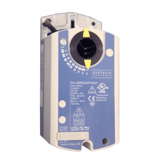
Figure 1: DA-088N Series Damper Actuator
Product Description
This document describes the hardware installation procedures for the
direct-coupled mounting of the DA-088N Series damper actuators.
General Installation Requirements
For proper installation and subsequent operation of each actuator, pay
special attention to the following recommendations:
-
Upon unpacking the product, inspect the contents of the carton for
shipping damages. Do not install damaged actuators.
-
Avoid areas where corroding, deteriorating or explosive vapors,
fumes or gases may be present.
-
Ensure that all equipment is installed according to local, regional,
and national regulations.
Personal injury or loss of life may occur if you do not follow a
procedure as specified.
Equipment damage or loss of data may occur
follow a procedure as specified.
Take reasonable precautions to prevent electrostatic
discharges to the controller when installing, servicing or
operating the controller. Discharge accumulated static
electricity by touching one's hand to a well-grounded object
before working with the controller.
H a r d w a r e I n s t a l l a t i o n G u i d e
Product Parts
if
you do not
a)
Actuator
b)
Position indicator
c)
Mounting bracket
d)
Mounting screws
e)
4 mm hex key
f)
Shaft insert for use with 3/8-inch (8-10 mm) shafts
Advertisement
Table of Contents

Related Manuals for Distech Controls DA-088N Series


Summary of Contents for Distech Controls DA-088N Series
- Page 1 Product Description Product Parts This document describes the hardware installation procedures for the direct-coupled mounting of the DA-088N Series damper actuators. General Installation Requirements For proper installation and subsequent operation of each actuator, pay special attention to the following recommendations: Upon unpacking the product, inspect the contents of the carton for shipping damages.
-
Page 2: Product Components
1. Determine whether the damper blades will rotate clockwise or Product Components counterclockwise to open. See Figure 3. 2. If the blades will rotate counterclockwise, slide the manual override switch to manual, and move the adjustment lever to the right. Actuator Components Return the switch to automatic. -
Page 3: Operation
Figure 7. Mounting Actuator to Damper Shaft. Figure 4. Removing 1/2-inch Ø shaft guide for 3/8-in or 5/8-in shaft. Figure 8. Installing the Position Indicator (b). Figure 5. 3/8 Ø inch shaft, see Figure 2, Item f. 1. A 3/8-inch shaft adapter is provided in actuator package. 2. - Page 4 Active voltage range: Uw = 2 to 10 Vdc Control signal adjustment DA-088N024PAXXP and DA-088N024PA2XP: For sequencing and the electronic limitation of the angle of rotation. Use the Uo potentiometer to set the offset (start point) between 0 to 5 Vdc. Use the U potentiometer to set the slope (span) between 2 to 30 Vdc.
-
Page 5: Manual Override
When turning the self-adaptive feature on or after the software reset with the feature on, the actuator will enter a five-minute calibration cycle as the actuator adjusts to the rotation limits of the system. A software reset happens after power on or may be caused by electrostatic discharge (ESD) at levels of 2kV and above. - Page 6 Dual Auxiliary Switch Setting Mechanical Range Limitation and Self-Adapt Feature For DA-088N024FX2XP, DA-088N024PA2XP, DA-088N024PX2XP only. Factory setting: 1. To use the entire 0 to 10V input signal to control the adjusted range, raise the tab located on the lower left-hand side of the actuator and A = 5°...
-
Page 7: Wiring Diagrams
Wiring All wiring must conform to NEC and local codes and regulations. Use earth ground isolating step-down Class 2 transformers. Do not use autotransformers. The sum of the VA ratings of all actuators and all other components powered by one transformer must not exceed the rating of the transformer. - Page 8 Table 1. 3-position Control 24 Vac. DA-088N024Fxxxx, continued Each wire has the standard symbol printed on it. See Table 1. Terminal Color Standard Function Designation Symbol 24 Vac Power Supply Floating Control. Supply (SP) Control signal clockwise Violet Control signal Orange counterclockwise Switch A Common...
- Page 9 Figure 23. 0 to 10 Vdc Modulating Control. 9/14...
-
Page 10: Start-Up / Commissioning
Check the Auxiliary Switch B: 1. Set the DMM dial to ohms (resistance) or continuity check. Start-Up / Commissioning 2. Connect wires S4 and S6 to the DMM. The DMM should indicate open circuit or no resistance. 1. Check that the wires are connected correctly. 3. - Page 11 Retrofit Wiring Modulating Control Distech Controls Siemens Belimo Honeywell Johnson (0 to 10 Vdc) DA-088N Series Series Series MN7505 Series M9104 Series GLB Series NMB Series MN7510 Series* M9109 Series* Function Color Number Color Number Color Number Color Number Color...
- Page 12 Dimensions Figure 24. Dimensions of the DA-ASK75.7U Weather Shield in Inches (Millimeters). 12/14...
- Page 13 Dimensions (cont’d) Figure 25. Dimensions of the DA-088N Actuator and Mounting Bracket in Inches (mm) 13/14...
- Page 14 ©, Distech Controls Inc., 2014. All rights reserved. While all efforts have been made to verify the accuracy of information in this manual, Distech Controls is not responsible for damages or claims arising from the use of this manual. Persons using this manual are assumed to be trained HVAC specialist / installers and are responsible for using the correct wiring procedures and maintaining safe working conditions with fail-safe environments.
Need help?
Do you have a question about the DA-088N Series and is the answer not in the manual?
Questions and answers