Table of Contents
Advertisement
Quick Links
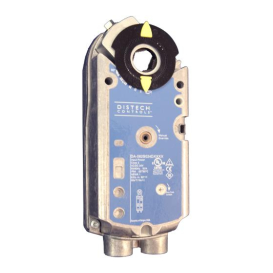
DA-062S Series
Damper Actuator, 62lb.-in., Spring Return
Figure 1: DA-062S Series Damper Actuator
Product Description
This document describes the hardware installation procedures for the
DA-062S Series damper actuators.
General Installation Requirements
For proper installation and subsequent operation of each actuator, pay
special attention to the following recommendations:
-
Upon unpacking the product, inspect the contents of the carton for
shipping damages. Do not install damaged actuators.
-
Avoid areas where corroding, deteriorating or explosive vapors,
fumes or gases may be present.
-
Ensure that all equipment is installed according to local, regional,
and national regulations.
Personal injury or loss of life may occur if you do not follow a
procedure as specified.
Equipment damage or loss of data may occur if you do not
follow a procedure as specified.
Keep these instructions together with the actuator or with the
plant documentation!
Do not open the actuator.
Spring preload
Factory set preload: 5°
Unload by power or mechanical.
H a r d w a r e I n s t a l l a t i o n G u i d e
Take reasonable precautions to prevent electrostatic
discharges to the controller when installing, servicing or
operating the controller. Discharge accumulated static
electricity by touching one's hand to a well-grounded object
before working with the controller.
Product Parts
a)
Actuator
b)
Self-centering shaft adapter
c)
Position indicator
d)
Shaft adapter locking clip
e)
Position indicator adapter
f)
Mounting bracket
g)
Mounting screws
h)
3 mm hex wrench
i)
Auxiliary switch adjustment tool
Advertisement
Table of Contents

Related Manuals for Distech Controls DA-062S Series


Summary of Contents for Distech Controls DA-062S Series
- Page 1 H a r d w a r e I n s t a l l a t i o n G u i d e DA-062S Series Damper Actuator, 62lb.-in., Spring Return Figure 1: DA-062S Series Damper Actuator Take reasonable precautions to prevent electrostatic discharges to the controller when installing, servicing or operating the controller.
-
Page 2: Product Components
Connection cable for adjustment auxiliary switches or feedback potentiometer 17. Adjustment tool for: auxiliary switches (11), Gear train lock pin offset/span (4 and 5), and lock pin (9) 1/2-inch NSPT conduit connections Figure 2. Components of the DA-062S Series Actuators. 2/14... - Page 3 Limits for Angular Rotation Shaft Mounting 3/14...
-
Page 4: Mounting And Installation
Mounting and Installation Flip the actuator to select either clockwise or counterclockwise fail-safe rotation of the damper shaft. Follow steps 1, 2, and 3 of the following table to determine the correct actuator mounting orientation. Do not open the actuator. If the actuator is inoperative, replace the unit. Table 1. -
Page 5: Operation
Mechanical Range Adjustment Operation The angular rotation is adjustable between 0° and 90° at 5-degree intervals. For DA-062S024Pxxxx, DA-062S024Qxxxx: To limit the range of shaft movement: Apply a continuous 0 to 10 Vdc, or 2 to 10 Vdc control signal between 1. -
Page 6: Dip Switch Functionality
Settings DIP Switch Functionality Uo = 2V; U = 16V DA-062S024QXXXP / XXXX and DA-062S024QX2XP / X2XX Umin = minimum control signal Umax = maximum control signal Description Label Description Function Inverse Input Signal Direct-Acting Acting Inversion Inverse- Feedback Direct-Acting Acting Signal feedback... - Page 7 Over-current protection for supply lines is maximum 10A. Wire Designations Each wire has the standard symbol printed on it. Applicable Standard Terminal Actuator Symbol Function Designations Color Supply (SP) Neutral (SN) Black Control signal clockwise Violet Control signal counterclockwise Orange 24 Vac/dc Input signal: 0 to 10 Vdc (DA-062S024Pxxxx) or 2 to 10 Vdc (DA- Gray...
-
Page 8: Wiring Diagrams
Wiring Diagrams DA-062S024Dxxxx 24 Vac/dc Class 2 2-position control DA-062S120Dxxxx 120 Vac 2-position control DA-062S024Fxxxx 24 Vac/dc Class 2 3-position control DA-062S024Qxxxx (2-10V) DA-062S024Pxxxx (0-10V) Class 2 24 Vac/dc Modulating control 8/14... - Page 9 Wiring Diagrams (cont’d) Special Applications DA-062S024QXXXP 4 to 20 mA 9/14...
-
Page 10: Start-Up / Commissioning
Connect wires S1 and S2 to the DMM. The DMM should indicate open circuit or no resistance. Start-Up / Commissioning Apply the input signal as in Step 1f, to wire 8 (gray). The DMM should indicate contact closure as the actuator shaft coupling reaches the setting of switch A. -
Page 11: Troubleshooting
1. Check Operation: Set the DMM dial to ohms (resistance) or continuity check. Switch on 120 Vac power. Connect wires S1 and S3 to the DMM. The DMM should Allow the actuator shaft coupling to rotate from 0 to 90°. indicate an open circuit or no resistance. - Page 12 Retrofit Wiring Distech Controls Siemens Belimo Honeywell Johnson Modulating Control DA-062S Series GMA Series LF Series, NF Series MS7505 Series M9208 Series (0 to 10 Vdc) Function Color Number Color Number Color Number Color Number Color Number Supply (24V) Common...
- Page 13 Dimensions (cont’d) Figure 8. Dimensions of the DA-ASK75.7U Weather Shield in Inches (mm). Figure 9. DA-062S Series Actuator and Mounting Bracket Dimensions 13/14...
- Page 14 ©, Distech Controls Inc., 2014. All rights reserved. While all efforts have been made to verify the accuracy of information in this manual, Distech Controls is not responsible for damages or claims arising from the use of this manual. Persons using this manual are assumed to be trained HVAC specialist / installers and are responsible for using the correct wiring procedures and maintaining safe working conditions with fail-safe environments.
Need help?
Do you have a question about the DA-062S Series and is the answer not in the manual?
Questions and answers