Table of Contents
Advertisement
Quick Links
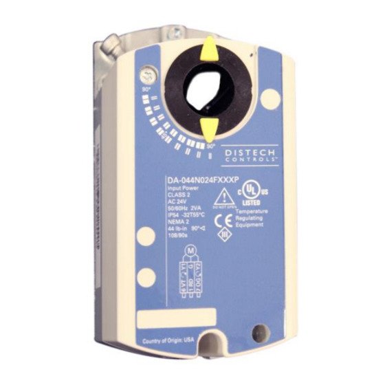
DA-044N Series
Damper Actuator, 44lb.-in., Non-Spring Return, 24V
Figure 1: DA-044N Series Damper Actuator
Product Description
This document describes the hardware installation procedures for the
direct-coupled mounting of the DA-044N Series damper actuators.
General Installation Requirements
For proper installation and subsequent operation of each actuator, pay
special attention to the following recommendations:
-
Upon unpacking the product, inspect the contents of the carton for
shipping damages. Do not install damaged actuators.
-
Avoid areas where corroding, deteriorating or explosive vapors,
fumes or gases may be present.
-
Ensure that all equipment is installed according to local, regional,
and national regulations.
Personal injury or loss of life may occur if you do not follow a
procedure as specified.
Equipment damage or loss of data may occur if you do not
follow a procedure as specified.
Take reasonable precautions to prevent electrostatic
discharges to the controller when installing, servicing or
operating the controller. Discharge accumulated static
electricity by touching one's hand to a well-grounded object
before working with the controller.
H a r d w a r e I n s t a l l a t i o n G u i d e
Product Parts
a)
Actuator
b)
Position indicator
c)
Mounting bracket
d)
Mounting screws
e)
4 mm hex key
f)
Shaft insert for use with 3/8-inch (8-10 mm) shafts
Advertisement
Table of Contents

Related Manuals for Distech Controls DA-044N Series


Summary of Contents for Distech Controls DA-044N Series
- Page 1 Product Description Product Parts This document describes the hardware installation procedures for the direct-coupled mounting of the DA-044N Series damper actuators. General Installation Requirements For proper installation and subsequent operation of each actuator, pay special attention to the following recommendations:...
-
Page 2: Product Components
Post Header AMP Product Components Actuator Components Figure 4: DA-044N024PXXXA - Uses a Post Header for connection purposes rather than cable connections. The Post Header AMP has two identical sets of contacts. Instructions Estimated Installation Time 30 minutes Required Tools 4 mm hex wrench 4 mm (5/32-inch) drill bit and drill Figure 2: Parts of the Actuator... -
Page 3: Mounting And Installation
Figure 7. 3/8 Ø inch shaft, see Figure 2, Item f. Figure 5. Setting the Direction of Rotation. 1. A 3/8-inch shaft adapter is provided in actuator package. 2. Hold the shaft insert so that the raised tabs are inserted last when Mounting and Installation placing the insert into the back of the actuator. -
Page 4: Operation
Figure 12. Actuator position (100% = angle of rotation Figure 10. Installing the Position Indicator (b). 90°*) Setting for Control input signal slope Offset (start point) offset U: Slope Uw: Figure 13. Active voltage range (Ys changes) *When the mechanical limitation of the angle of rotation and self-adapt function are ON, 100% does not equal 90°. -
Page 5: Manual Override
Settings: Uo = 2 Vdc; U = 16 Vdc Electronic limitation: Angle of rotation: Ys = 50% (45°) Slope: U = 16V Active voltage range: Uw = 2 to 10 Vdc Figure 16. Self-adapt Switch. When turning the self-adaptive feature on or after the software reset with the feature on, the actuator will enter a five-minute calibration cycle as the actuator adjusts to the rotation limits of the system. - Page 6 Figure 21. Moving the Mechanical Range Stop. To use the entire 0 to 10V input signal to control the mechanically limited range, see Figure 16 for setting self-adaptive features. Figure 19. Manual Override. Example: Stop set screw at 70° Self-adapt switch ON Dual Auxiliary Switch Setting Input signal Y = 5 Vdc The damper will be at 35°...
-
Page 7: Wiring Diagrams
Slope (span) and Offset Adjustment Wiring For DA-044N024PAXXP and DA-044N024PA2XP only All wiring must conform to NEC and local codes and regulations. Factory setting: Use earth ground isolating step-down Class 2 transformers. Do not use autotransformers. U 10 Slope (span) The sum of the VA ratings of all actuators and all other components Offset Uo = 0 powered by one transformer must not exceed the rating of the... - Page 8 Table 1. 3-position Control 24 Vac. DA-044N024Fxxxx, continued Each wire has the standard symbol printed on it. See Table Terminal Color Standard Function Designation Symbol 24 Vac Power Supply Floating Control. Supply (SP) Control signal clockwise Violet Control signal Orange counterclockwise Switch A Common Gray/red...
- Page 9 Determine the supply transformer rating by summing the total VA of all Terminal Strip - DA-044N024PXXXT actuators used. It is recommended that one transformer power no Maximum wire size for the DA-044N024PXXXT is 14 more than 12 actuators. AWG. Installations requiring Conformance All wiring for CE rated actuators must only be separated extra low voltage (SELV) or protective extra...
-
Page 10: Start-Up / Commissioning
2. Check that offset and slope are set correctly, if used. 3. Check that the direction of rotation switch/cable matches the rotation of the damper shaft. 4. Connect wires 1 (red) and 2 (black) to a Digital Multimeter (DMM) with the dial set at AC V to verify that the operating voltage is within range. - Page 11 Retrofit Wiring Modulating Control Distech Controls Siemens Belimo Honeywell Johnson (0 to 10 Vdc) DA-044N Series Series Series MN7505 Series M9104 Series GLB Series NMB Series MN7510 Series* M9109 Series* Function Color Number Color Number Color Number Color Number Color...
- Page 12 Dimensions Figure 34. Dimensions of the DA-ASK75.7U Weather Shield in Inches (Millimeters). 12/14...
- Page 13 Dimensions (cont’d) Figure 35. Dimensions of the DA-044N Actuator and Mounting Bracket in Inches (mm) 13/14...
- Page 14 ©, Distech Controls Inc., 2014. All rights reserved. While all efforts have been made to verify the accuracy of information in this manual, Distech Controls is not responsible for damages or claims arising from the use of this manual. Persons using this manual are assumed to be trained HVAC specialist / installers and are responsible for using the correct wiring procedures and maintaining safe working conditions with fail-safe environments.
Need help?
Do you have a question about the DA-044N Series and is the answer not in the manual?
Questions and answers