Table of Contents
Advertisement
Quick Links
Advertisement
Table of Contents

Subscribe to Our Youtube Channel
Related Manuals for Bender ISOMETER isoBAT425


Summary of Contents for Bender ISOMETER isoBAT425
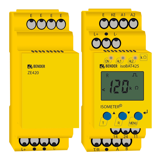
- Page 1 Manual ISOMETER® isoBAT425 with A1 A2 coupling impedance ZE420 isoBAT425 ZE420 < ISOMETER Insulation monitoring device for batteries up to DC 500 V MENU Software version: D0560 isoBAT425_D00308_04_M_XXEN/07.2020...
- Page 2 E-mail: info@bender.de Web: www.bender.de Customer service Service hotline: 0700-BenderHelp (Telephone and Fax) Carl-Benz-Strasse 8 • 35305 Gruenberg • Germany © Bender GmbH & Co. KG Tel.:+49 6401 807-760 All rights reserved. Fax:+49 6401 807-629 Reprinting only with permission of the publisher.
-
Page 3: Table Of Contents
Table of contents 1. Important information ..............5 3.2.7 Error codes ........... .11 3.2.8 Connection monitoring . - Page 4 Table of contents 5. Operation of the device ..............18 8. Modbus register assignment of the ISOMETER® .......25 5.1 Display elements ..........18 8.1 Device-specific data type of the ISOMETER®.
-
Page 5: Important Information
• Delivery of replacement devices for faulty or incorrectly delivered Bender devices This symbol denotes information intended to assist the user in • Extended guarantee for Bender devices, which includes an in-house repair service or making optimum use of the product. -
Page 6: Field Service
This operating manual, especially the safety instructions, must be observed by all person- Bender is happy to provide training regarding the use of test equipment. The dates of nel working on the device. Furthermore, the rules and regulations that apply for accident training courses and workshops can be found on the Internet at www.bender-de.com ->... -
Page 7: Safety Instructions
2.1 General safety instructions 2.3 Intended use Part of the device documentation in addition to this manual is the enclosed "Safety instructions for Bender products". Only skilled persons are permitted to carry out the work necessary to 2.2 Work activities on electrical installations install, commission and run a device or system. -
Page 8: Function
• RS-485 (galvanically isolated) including the following protocols: ton "R" is pressed or the supply voltage U is interrupted. BMS interface (Bender measuring device interface) for data exchange with other The device function can be tested using the test button "T". Parameters are assigned to •... -
Page 9: Measured Values
Function Function In addition, the coupling impedance contains two capacitances for a necessary minimum 3.2.3 Monitoring of the insulation resistance and the system leakage leakage capacitance to earth. capacitance The insulation resistance R as well as the system leakage capacitance C to earth are me- 3.2.2 Measured values asured. -
Page 10: Measuring Pulse Period Duration And Operating Times
Function Function The image below shows the operating mode of the voltage comparators with the resul- 3.2.6 Fault diagnosis ting messages. 3.2.6.1 Insulation fault to earth Limit Comparator Status Message The displayed value R of the ISOMETER® is the total insulation resistance R to earth. -
Page 11: Battery Voltage
Function Function 3.2.6.3 Battery voltage The self test can take a few minutes. It can be suppressed for the duration of the device start by setting the parameter "S.Ct = off" in the "SEt" menu. This allows the ISOMETER® to The nominal system voltage U is monitored with the voltage comparators described enter measurement mode quickly after connecting the supply voltage U... -
Page 12: Reset
Function Function 3.2.9.2 Reset 3.2.9.4 Automatic self test Briefly pressing (0.2 s < t < 1.5 s) the external T/R button, pressing and holding (t > 1.5 s) During an automatic test (duration approx. 30 s), the measuring functions of the ISOME- the "R"... -
Page 13: Checking The Operating System
Function Function 3.2.9.6 Checking the operating system No hysteresis is taken into account and the alarms do not remain stored in the fault memory. The following elements are part of the operating system check: A measured value that reaches the go status after the device has started triggers the •... -
Page 14: Password Protection (On, Off)
. An alarm will continuously be signalled until the threshold value of the The BMS protocol is an essential component of the Bender measuring device interface respective measured value is not violated (including hysteresis) for the period of t wit- (BMS bus protocol). -
Page 15: Installation, Connection And Commissioning
4. Installation, connection and commissioning Installation, connection and commissioning The dimension diagram, sketch for screw mounting and DIN rail mounting: Only skilled persons are permitted to carry out the work necessary to install, commission and run a device or system. Risk of fatal injury from electric shock! Touching live parts of the system carries the risk of: DANGER... -
Page 16: Wiring Diagram
Installation, connection and commissioning 4.2 Wiring diagram Bat 2 . . . Bat 1 A1 A2 ZE420 isoBAT425 < ISOMETER MENU off COM465IP Insulation fault to earth System leakage capacitance to earth RS-485 Test / Reset Insulation fault between the plus and minus strings (cross fault) J-Y (St)Y 2x0,6 For details about the conductor cross sections required for wiring, refer to the technical data from... -
Page 17: Commissioning
Installation, connection and commissioning Installation, connection and commissioning Wiring diagram legend: 4.3 Commissioning Terminal Connections 1. Check that the ISOMETER® is properly connected to the system to be monitored. Connection to the supply voltage via fuse (line protection). 2. Connect the supply voltage U to the ISOMETER®. -
Page 18: Operation Of The Device
5. Operation of the device Operation of the device The menu structure is illustrated schematically on the following pages. 5.1 Display elements After pressing the "MENU" button for > 1.5 s, the first menu item "AL" appears. Use (Enter) buttons for navigation and settings. Device front/display Function green - on... -
Page 19: Menu Overview
Operation of the device Operation of the device 5.2 Menu overview 5.3 "AL" menu 5.3.1 Response value setting Measurement display Standard display The two parameters that monitor the insulation resistance R , "R1" and "R2", can be found Menu selection Menu in the response value menu "AL". -
Page 20: Out" Menu
Operation of the device Operation of the device 5.4 "out" menu K1 "r1" K2 "r2" LEDs Alarm description Display FAC Cs Display 5.4.1 Configuration of the alarm relay operating mode Device start with S.AL S.AL alarm Alarm relay K1 Alarm relay K2 Description FAC = Factory setting;... -
Page 21: T" Menu
) / (100 % + x %) = (200 % * R ) / (100 % - x %) For Bender Service only The measured value is indicated in the history memory. FAC = Factory setting; Cs = Customer settings... -
Page 22: Data Access Using The Bms Protocol
6. Data access using the BMS protocol Data access using the BMS protocol The BMS protocol is an essential component of the Bender measuring device interface (BMS bus protocol). ASCII characters are used for the data transfer. BMS channel no. -
Page 23: Data Access Using The Modbus Rtu Protocol
7. Data access using the Modbus RTU protocol Data access using the Modbus RTU protocol Requests to the ISOMETER® can be made using the function code 0x03 (read multiple 7.2 Write Modbus register (parameter setting) registers) or the command 0x10 (write multiple registers). The ISOMETER® generates a Registers in the device can be modified with the Modbus command 0x10 (set multiple function-related answer and sends it back. -
Page 24: Exception Code
Data access using the Modbus RTU protocol Data access using the Modbus RTU protocol 7.3 Exception code If a request cannot be answered for whatever reason, the ISOMETER® will send a so-called exception code with which possible faults can be narrowed down. Exception code Description 0x01... -
Page 25: Modbus Register Assignment Of The Isometer
8. Modbus register assignment of the ISOMETER® Modbus register assignment of the ISOMETER® Depending on the device condition, the information in the registers is the measured value without alarm; the measured value with alarm 1; the measured value with alarm 2; Register Property Description... - Page 26 Modbus register assignment of the ISOMETER® Modbus register assignment of the ISOMETER® Register Property Description Format Unit Value range Register Property Description Format Unit Value range 0 = 8N1 8006 Clear fault memory UINT 16 0x434C "CL" 1 = 8O1 3017 Parity "Adr 2"...
-
Page 27: Device-Specific Data Type Of The Isometer
Modbus register assignment of the ISOMETER® Modbus register assignment of the ISOMETER® 8.1 Device-specific data type of the ISOMETER® 8.1.2.2 AT&T = Alarm type and test type (internal/external) Meaning 8.1.1 Device name The data format of the device name is specified below. Word 0x01 0x02... -
Page 28: R&U = Range And Unit
Modbus register assignment of the ISOMETER® Modbus register assignment of the ISOMETER® 8.1.2.3 R&U = Range and unit 8.1.3 Alarm assignment of the alarm relays Several alarms can be assigned to each alarm relay. For the assignment of each alarm re- Meaning lay, a 16-bit register is used with the bits described below. -
Page 29: Channel Descriptions
Modbus register assignment of the ISOMETER® Modbus register assignment of the ISOMETER® 8.2 Channel descriptions To convert parameter data, data type descriptions are required. Text representation is not necessary in this case. Measured value description/ Value Description of parameters Value alarm message operating Note message... -
Page 30: Isodata Data String
9. IsoData data string IsoData data string In IsoData mode, the ISOMETER® continuously sends the whole data string with a cycle time of approximately 1 second. Communication with the ISOMETER® in this mode is not possible and no additional sender may be connected via the RS-485 bus cable. IsoData is activated in the menu "out", menu item "Adr"... -
Page 31: Technical Data
10. Technical data Technical data 10.1 Tabular presentation Measuring circuit Measuring voltage U ..............................±12 V ( )* = Factory settings Measuring current Im at R = 0 Ω ........................≤ 110 μA Technical data isoBAT425 Internal resistance R .............................≥ 115 kΩ Permissible system leakage capacitance C Insulation coordination acc. - Page 32 Technical data Technical data Interface Flexible with ferrules with/without plastic sleeve..................0.25…2.5 mm Interface/protocol ......................RS-485/BMS, Modbus RTU, isoData Multi-conductor flexible with TWIN ferrules with plastic sleeve..............0.5…1.5 mm Baud rate ..............BMS (9.6 kbits/s), Modbus RTU (selectable), isoData (115.2 kbits/s) Opening force..................................
-
Page 33: Standards, Approvals And Certifications
Technical data Technical data Classification of climatic conditions acc. to IEC 60721: 10.2 Standards, approvals and certifications Stationary use (IEC 60721-3-3) .............. 3K23 (except condensation and formation of ice) The ISOMETER® has been developed in compliance with the following standards: Transport (IEC 60721-3-2) .............. -
Page 34: Index
INDEX Alarm relay Installation and connection 15 Response delay time 13 Assignment 20 Intended use 7 Response times 13 Interface/protocols 14 Response value setting 19 BMS 14 Commissioning 17 IsoData 14 Configuration Safety instructions 7 Modbus RTU 14 Alarm relay operating mode 20 Self test IsoData Fault memory 20... - Page 35 Bender GmbH & Co. KG Customer service Postbox 1161 • 35301 Grünberg • Germany Service hotline: 0700-BenderHelp (Telephone and Fax) Londorfer Straße 65 • 35305 Grünberg • Germany Carl-Benz-Straße 8 • 35305 Grünberg • Germany Tel.: +49 6401 807-0 Tel.:...
Need help?
Do you have a question about the ISOMETER isoBAT425 and is the answer not in the manual?
Questions and answers