
Subscribe to Our Youtube Channel
Related Manuals for Bender ISOMETER isoBAT425


Summary of Contents for Bender ISOMETER isoBAT425
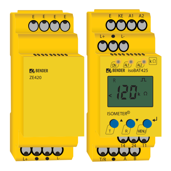
- Page 1 Manual EN ISOMETER® isoBAT425 Insulation monitoring device with coupling impedance ZE420 for batteries up to DC 500 V Software version: D0560 isoBAT425_D00308_05_M_XXEN/09.2023...
- Page 2 isoBAT425_D00308_05_M_XXEN/09.2023...
-
Page 3: Table Of Contents
Indication of important instructions and information...............6 Signs and symbols............................6 Service and Support............................6 Training courses and seminars........................7 Delivery conditions............................7 Inspection, transport and storage......................7 Warranty and liability.............................7 Disposal of Bender devices..........................8 1.10 Safety..................................8 Function.......................9 Intended use..............................9 Device features..............................9 Functional description........................... 9 2.3.1... - Page 4 Table of contents Connection...............................21 Commissioning...............................22 Operation......................24 Operating and display elements......................24 Menu overview...............................26 Displaying measured values........................27 Setting the response values (AL)......................28 4.4.1 Setting the response values for monitoring the insulation resistance........28 4.4.2 Setting the response values for undervoltage and overvoltage..........28 4.4.3 Response values overview.........................28 Configuring fault memory, alarm relays, and interfaces (out)............29...
- Page 5 ISOMETER® isoBAT425 Change log...............................51 isoBAT425_D00308_05_M_XXEN/09.2023...
-
Page 6: General Information
Protect from dust Temperature range Recycling RoHS directives Service and Support Information and contact details about customer service, repair service or field service for Bender devices are available on the following website: Fast assistance | Bender GmbH & Co. KG. isoBAT425_D00308_05_M_XXEN/09.2023... -
Page 7: Training Courses And Seminars
Regular face-to-face or online seminars for customers and other interested parties: www.bender.de > know-how > seminars. Delivery conditions The conditions of sale and delivery set out by Bender GmbH & Co. KG apply. These can be obtained in printed or electronic format. The following applies to software products: ‘Software clause in respect of the licensing of standard software as part of deliveries,... -
Page 8: Disposal Of Bender Devices
General information Disposal of Bender devices Abide by the national regulations and laws governing the disposal of this device. For more information on the disposal of Bender devices, refer to www.bender.de > service & support. 1.10 Safety If the device is used outside the Federal Republic of Germany, the applicable local standards and regulations must be complied with. -
Page 9: Function
• Two separately adjustable response value ranges from 10 k to 5 M (prewarning, alarm) • Device supply via wide-range power supply • RS-485 (galvanically isolated) including the following protocols: – BMS (Bender measuring device interface) for the data exchange with other Bender devices – Modbus RTU – IsoData (for continuous data output) •... -
Page 10: Ze420 Coupling Impedance
Function In the first step, the battery is assembled in two parallel strings (plus and minus string) which are not interconnected. During the second step, the two strings are connected to form a complete battery by means of another battery. The resulting measured values allow diagnosing the type and location of the insulation fault. -
Page 11: Monitoring Of The Insulation Resistance And The System Leakage Capacitance
ISOMETER® isoBAT425 Measured value ranges and resolution Value Interface Value range Resolution 999 k 1.0 M 10.0 M 0.1 M 20000 k Modbus, IsoData 20000 k ±99.9 V 0.1 V ±100 V ±500 V 500 V Modbus, IsoData ±500 V 0.1 V 0 nF 999 nF... -
Page 12: Messpulsperiodendauer Und Ansprecheigenzeiten
Function to improve the resolution and are time-delayed. The comparators of the system voltage monitoring use the non-delayed, non-averaged system voltage. Therefore, minor deviations between the response of the voltage monitoring and the indicated voltage value are possible. The parameters (U1˂, U1˃, U2˂ and U2˃) for monitoring the system voltage U can be set in the response value menu “AL”... -
Page 13: Fault Diagnosis
ISOMETER® isoBAT425 E.01 E.02 0.8 s 3.5 s 3.0 s 2.1 s 6.0 s 2.0 s 8.0 s 3.0 s 2.1 s 6.0 s 4.0 s 16.0 s 3.0 s 2.1 s 15.0 s 8.0 s 32.0 s 3.0 s 2.1 s 30.0 s The value only applies to C... -
Page 14: Error Codes
Function 2.3.6.3 Battery voltage The system voltage U is monitored with the voltage comparators described above. The insulation fault between the unconnected strings as well as the completion of the battery can be detected via these comparators. 2.3.7 Error codes In the event of a device error the display shows the respective error code. -
Page 15: Reset And Test
ISOMETER® isoBAT425 System connection monitoring The system connection monitoring monitors the connection of terminals “L+” and “L−” to the battery by means of the coupling impedance ZE420. An error is reported with the code E.02 and device error. The monitoring requires a resistance smaller than 12 k and a system leakage capacitance C larger than 80 nF between terminals “L+”... - Page 16 Function Sending a test command via the interface (COM): – The LCD shows “tES” and “CAL”. – A reset is carried out after the test. If triggering via the “T/R” button, the alarms remain active during the test (except the “Device fault” alarm). In addition, the message “test”...
-
Page 17: 2.3.10 Stop Mode
ISOMETER® isoBAT425 2.3.10 Stop mode The stop mode stops the measuring functions of the ISOMETER®. The measuring pulse voltage is 0 V and the input resistance of the system coupling has a high resistance. The LCD displays the message “StP”. The message “test”... -
Page 18: Password Protection (On, Off)
The ISOMETER® uses the serial hardware interface RS-485 with the following protocols: • BMS The BMS protocol is an essential component of the Bender measuring device interface (BMS bus protocol). Data transmission generally makes use of ASCII characters. • Modbus RTU Modbus RTU is an application layer messaging protocol, and it provides master/slave communication between devices that are connected via bus systems and networks. - Page 19 ISOMETER® isoBAT425 • IsoData The ISOMETER® sends an ASCII data string with a cycle of approximately 1 second. Communication with the ISOMETER® in this mode is not possible, and no additional sender may be connected via the RS-485 bus cable. The ASCII data string for the ISOMETER® is described in chapter 5.4. The IsoData protocol can be terminated by sending the command “Adr3”...
-
Page 20: Installation, Connection And Commissioning
Installation, connection and commissioning Installation, connection and commissioning Dimensions 45 70.5 31.1 47.5 74.5 Figure: Dimension diagram (in mm) Installation Figure: DIN rail mounting (left) or screw mounting (right) isoBAT425_D00308_05_M_XXEN/09.2023... -
Page 21: Connection
ISOMETER® isoBAT425 Connection DANGER Risk of fatal injury due to electric shock! Touching live parts of the system carries the risk of: • Risk of electrocution due to electric shock • Damage to the electrical installation • Destruction of the device Before installing the device and before working on its connections, make sure that the installation has been de-energised. -
Page 22: Commissioning
Installation, connection and commissioning Legend to wiring diagram Terminal Connections A1, A2 Connection to the supply voltage U via fuse (line protection): If supplied from an IT system, protect both lines by a fuse.* Connection to PE: Use same wire cross section as for “A1”, “A2”. Connection to the battery enclosure L+, L–... - Page 23 ISOMETER® isoBAT425 Check the functionality by a real insulation fault. Use a suitable resistor to check the ISOMETER® against earth in the system being monitored. isoBAT425_D00308_05_M_XXEN/09.2023...
-
Page 24: Operation
Operation Operation Operating and display elements Device front Operating elements Function Power LED AL1 AL2 Alarm LEDs (For codes see “Assigning the alarm messages to the relays”, page 29.) Up and down buttons – For navigating up or down in the menu settings. - Page 25 ISOMETER® isoBAT425 Display Display elements Function System voltage U Insulation resistance R System leakage capacitance C Monitored conductors L1 L2 L1 = L+ L2 = L– Voltage type DC Pulse symbol: error-free measured value update Voltage type AC °C Measured values and units μ...
-
Page 26: Menu Overview
Operation Menu overview Measurement display Menu selection Parameter selection Menu item Parameter Querying and setting response values Configuring fault memory, alarm relays and interface Setting delay times and self test cycles Setting device control parameters Querying software version Querying and clearing the history memory Going to the next-higher menu level isoBAT425_D00308_05_M_XXEN/09.2023... -
Page 27: Displaying Measured Values
ISOMETER® isoBAT425 Displaying measured values Overview Display Description Insulation resistance R 1 k … 10 M ✓ ± R k For R < 5 M , “+” or “–” R indicate as mainly on L+ or L– when |fault location| > 20 % or strings are open and |U | ≥... -
Page 28: Setting The Response Values (Al)
Operation Setting the response values (AL) 4.4.1 Setting the response values for monitoring the insulation resistance How to proceed Open menu “AL”. Select parameter “R1” for prewarning or parameter “R2” for alarm. Set value and confirm with Enter. 4.4.2 Setting the response values for undervoltage and overvoltage How to proceed Open menu “AL”. -
Page 29: Configuring Fault Memory, Alarm Relays, And Interfaces (Out)
ISOMETER® isoBAT425 Configuring fault memory, alarm relays, and interfaces (out) Call up menu „out“ to configure fault memory, alarm relays, and interfaces. 4.5.1 Configuring the relays Relay K1 Relay K2 Description Display Display Relay operating mode n/c or n/o FAC Factory settings Customer settings 4.5.2 Assigning the alarm messages to the relays... -
Page 30: Activating Or Deactivating Fault Memory
Operation K1 „r1“ K2 „r2“ LEDs Description Display Display Device start with alarm S.AL S.AL FAC Factory settings Customer settings LED off LED flashes LED on 4.5.3 Activating or deactivating fault memory Display Description Memory function for alarm messages (fault memory) FAC Factory settings Customer settings 4.5.4... -
Page 31: Setting Delay Times And Self Test Cycles (T)
2.0 auto: change to the period duration 8.0 s with the message “Battery voltage U is ok”. System connection test S.Ct Device test at device start Restore factory settings For Bender Service only FAC Factory settings Customer settings isoBAT425_D00308_05_M_XXEN/09.2023... -
Page 32: Reset To Factory Settings
Operation Reset to factory settings All settings with the exception of the interface parameters are reset to the factory settings. Press MENU button (> 1.5 s). Go to “SEt” and confirm with Enter. Go to “FAC” and confirm with Enter. Showing and deleting the history memory ADVICE The history memory saves the measured values for the first fault only. -
Page 33: Data Access Via Rs-485 Interface
ISOMETER® isoBAT425 Data access via RS-485 interface Data access using the BMS protocol The BMS protocol is an essential component of the Bender measuring device interface (BMS bus protocol). Data transmission generally makes use of ASCII characters. BMS channel no. -
Page 34: Writing The Modbus Register (Parameter Setting)
Data access via RS-485 interface Command of the master to the ISOMETER® In the following example, the master of the ISOMETER® requests the content of register 1003 using address 3. The register contains the channel description of measuring channel 1. Byte Name Example... -
Page 35: Exception Code
ISOMETER® isoBAT425 Response of the ISOMETER® to the master Byte Name Example Byte 0 ISOMETER® Modbus address 0x03 Byte 1 Function code 0x10 Byte 2, 3 Start register 0x0BBB Byte 4, 5 Number of registers 0x0001 Byte 6, 7 CRC16 checksum 0x722A 5.2.3 Exception code... -
Page 36: Modbus Register Assignment
Data access via RS-485 interface Modbus register assignment 5.3.1 Modbus measured value registers Depending on the device condition, the information in the registers is the measured value without alarm, the measured value with alarm 1, the measured value with alarm 2, or the device error. For more information see , page 37. - Page 37 ISOMETER® isoBAT425 5.3.1.2 Float = Floating point value of the channels Representation of the bit order for processing analogue measured values according to IEEE 754 Word 0x00 0x01 Byte HiByte LoByte HiByte LoByte 31 30 29 28 27 26 25 24 23 22 21 20 19 18 17 16 15 14 13 12 11 10 exponent mantissa sign...
- Page 38 Data access via RS-485 interface 5.3.1.4 R&U = Range and unit Meaning Unit Invalid (init) No unit Baud °C °F Second Minute Hour Month Range of validity Actual value The actual value is lower The actual value is higher Invalid value •...
-
Page 39: Modbus Parameter Register
ISOMETER® isoBAT425 5.3.1.5 Channel descriptions Value Description of measured value / message Comments 1 (0x01) Insulation fault 71 (0x47) Insulation fault Insulation resistance R 76 (0x4C) Voltage Measured value in V 77 (0x4D) Undervoltage 78 (0x4E) Overvoltage 82 (0x52) Capacitance Measured value in F 86 (0x56) Insulation fault... - Page 40 Data access via RS-485 interface Register Property Description Format Unit Value range 3010 Reserved UINT 16 cross fault lower limit 3 … U 3011 UINT 16 CrossL CrossH Memory function for alarm 0 = off 3012 UINT 16 messages (fault memory) “M” 1 = on 0 = n/o 3013...
- Page 41 ISOMETER® isoBAT425 Register Property Description Format Unit Value range 3028 Alarm assignment of relay K2 “r2” UINT 16 Bit 10 … Bit 1 0 = auto 0.8 1 = auto 2.0 2 = 0.8 3029 Measuring pulse period duration UINT 16 3 = 2.0 4 = 4.0 5 = 8.0...
- Page 42 Data access via RS-485 interface Display indication Meaning rx +R2 < Alarm R2 - Fault R at L+ Alarm R2 - Fault R at L– rx –R2 < Alarm message U - undervoltage rx U < V Alarm message U - overvoltage rx U >...
-
Page 43: Isodata Data String
ISOMETER® isoBAT425 IsoData data string In IsoData mode the ISOMETER® sends the entire data string roughly once per second. Communication with the ISOMETER® in this mode is not possible and no additional sender may be connected via the RS-485 bus cable. -
Page 44: Technical Data
Technical data Technical data Technical data isoBAT425 ( )* = Factory settings Insulation coordination acc. to IEC 60664-1/-3 Definitions Measuring circuit (IC1) L+, L- Supply circuit (IC2) A1, A2 Output circuit (IC3) 11, 14, 24 Control circuit (IC4) E, KE, T/R, A, B Rated voltage 400 V Overvoltage category... - Page 45 ISOMETER® isoBAT425 Supply voltage Supply voltage U AC 100…240 V / DC 24…240 V Tolerance of U –30…+15 % Frequency range U 47…63 Hz Power consumption ≤ 3 W, ≤ 9 VA Monitored IT system Nominal system voltage U DC 0…400 V Tolerance of U +25 % Measuring circuit...
- Page 46 Technical data Time response Response time t at R = 0.5 × R for the measuring pulse period durations = 0.8 s ≤ 3.5 s = 2 s ≤ 8 s = 4 s ≤ 16 s = 8 s ≤...
- Page 47 ISOMETER® isoBAT425 Switching elements Switching elements 2 x 1 n/o contacts, common terminal 11 Operating principle n/c or n/o (n/o)* Electrical endurance 10.000 cycles Electrical endurance at DC 30 V / ≤ 0.1 A (L/R = 7 ms) cycles Contact data acc. to IEC 60947-5-1 Utilisation category AC-12 / AC-14 / DC-12 / DC-12 / DC-12 Rated operational voltage...
-
Page 48: Technical Data Ze420
Technical data Enclosure material polycarbonate DIN rail mounting acc. to IEC 60715 Screw fixing 2 x M4 with mounting clip Weight ≤ 150 g Technical data ZE420 Insulation coordination acc. to IEC 60664-1/-3 Definitions Measuring circuit (IC1) L+, L– Control circuit (IC2) Rated voltage 400 V Overvoltage category... -
Page 49: Connection
ISOMETER® isoBAT425 Classification of climatic conditions acc. to IEC 60721 Stationary use (IEC 60721-3-3) 3K22 Transport (IEC 60721-3-2) 2K11 Long-term storage (IEC 60721-3-1) 1K22 Classification of mechanical conditions acc. to IEC 60721 Stationary use (IEC 60721-3-3) 3M11 Transport (IEC 60721-3-2) Long-term storage (IEC 60721-3-1) 1M12 Other... -
Page 50: Standards And Certifications
ZE420 EU Declaration of Conformity Hereby, Bender GmbH & Co. KG declares that the device covered by the Radio Directive complies with Directive 2014/53/EU. The full text of the EU Declaration of Conformity is available at the following Internet address: https://www.bender.de/fileadmin/content/Products/CE/CEKO_isoXX425.pdf... - Page 51 ISOMETER® isoBAT425 Change log Date Document Valid from State/Changes version software version 09.2023 D0560 V1.xx Editorial revision • Transfer to SMC incl. new CI and new chapter structure • Better separation of descriptive and instructional texts (function/ operation) Standards: Link to website added. Term: “stop mode”...
- Page 52 isoBAT425_D00308_05_M_XXEN/09.2023...
- Page 53 ISOMETER® isoBAT425 isoBAT425_D00308_05_M_XXEN/09.2023...
- Page 54 Alle Rechte vorbehalten. 35305 Grünberg Nachdruck und Vervielfältigung nur mit Germany Genehmigung des Herausgebers. © Bender GmbH & Co. KG, Germany Subject to change! The specified Tel.: +49 6401 807-0 All rights reserved. standards take into account the edition info@bender.de Reprinting and duplicating only with valid until 09.2023 unless otherwise...
Need help?
Do you have a question about the ISOMETER isoBAT425 and is the answer not in the manual?
Questions and answers