Bender ISOMETER isoRW685W-D Manual
Hide thumbs
Also See for ISOMETER isoRW685W-D:
- Manual (8 pages) ,
- Quick start manual (8 pages) ,
- Manual (87 pages)
Table of Contents
Advertisement
Quick Links
Advertisement
Table of Contents

Related Manuals for Bender ISOMETER isoRW685W-D


Summary of Contents for Bender ISOMETER isoRW685W-D
- Page 1 Manual ISOMETER® isoRW685W–D Insulation Monitoring Device for IT AC systems with galvanically connected rectifiers and inverters and for IT DC systems specific to railway applications Software version: D438 V1.27 isoRW685W-D_D00178_07_M_XXEN/12.2021...
- Page 2 Email: info@bender.de Web: www.bender.de Customer service: Service hotline: 0700-BenderHelp (Telephone and Fax) Carl-Benz-Straße 8 • 35305 Grünberg • Germany © Bender GmbH & Co. KG Tel.:+49 6401 807-760 All rights reserved. Fax:+49 6401 807-629 Reproduction only with permission of the publisher.
-
Page 3: Table Of Contents
Table of Contents 1. Important information ................6 6. Connection ....................17 1.1 How to use this manual ..........6 6.1 Connection conditions. - Page 4 Table of Contents (1.2) DC alarm ..........28 (5.3) Interface .
- Page 5 Table of Contents 10.5 BS bus ............. . 42 10.5.1 Master-slave principle .
-
Page 6: Important Information
1.2 Technical support 1.2.1 End customer support and advice This manual is intended for qualified personnel working in electrical Technical support by phone or e-mail for all Bender products engineering and electronics! • Questions concerning specific customer applications • Commissioning Read the manual before you begin to mount, connect, and commission •... -
Page 7: Training Courses
• Old electrical and electronic equipment from users other than private households Sale and delivery conditions can be obtained from Bender in printed or electronic format. which was introduced to the market after 13 August 2005 must be taken back by the manufacturer and disposed of properly. -
Page 8: Safety Instructions
Part of the device documentation in addition to this manual is the enclosed "Safety in- Installation inside a control cabinet structions for Bender products". If the ISOMETER® is installed inside a control cabinet, the insulation fault message must be audible and/or visible to attract attention. -
Page 9: Function
• Remote diagnosis via the Internet (made available by Bender Service only) of the system type 3AC, AC or DC and the required use of the appropriate terminals L1/+, • RS-485/BS (Bender sensor bus) for data exchange with other Bender devices via L2, L3/-. -
Page 10: Interfaces
3.4 Interfaces • Communication protocol Modbus TCP • Communication protocol Modbus RTU • BCOM for communication of Bender devices via Ethernet • BS bus for communication of Bender devices (RS-485) • isoData for recording and managing measured values • Integrated web server for reading out measured values and setting parameters 3.5 Self test... -
Page 11: Device Overview
4. Device overview Device overview 4.1 Dimensions 4.2 Device variants iso685(W)-D… The iso685 variant features a high-resolution graphic LC display and operating controls for direct operation of the device functions. isoxx685(W)-D… It cannot be combined with an FP200. Enclosure iso685…-device familiy – dimensions in mm isoRW685W-D_D00178_07_M_XXEN/12.2021... -
Page 12: Connection And Panel
Front Rear Connection top REMOTE Control panel Connction bottom REMOTE interface to connect the FP200(W) * Optional expansion interface for Bender products Bottom Multifunctional I/O interface (see „Connection of the X1 interface“) ETH (X2) Ethernet interface Switchable terminating resistor for termination of the RS-485 interface... -
Page 13: Display Elements And Device Buttons
Device overview Device overview 4.4 Display elements and device buttons 4.4.2 device buttons You can adjust the device settings in the respective menu using the menu buttons. De- pending on the menu entry, one of the options displayed below is assigned to the but- tons. -
Page 14: Operating And Navigating
Device overview Device overview 4.5 Operating and navigating 4.5.4 Character input Use the (forward) and (backward) 4.5.1 Menu selection Ethernet x.3.2 buttons to select a character from the dis- Activate the menu by pressing the play. To enter the next character, use the IT system "MENU"... -
Page 15: Mounting
5. Mounting Mounting 5.1 Common information 5.2 Mounting spaces Only qualified personnel are permitted to carry out the work necessary to install, commission and run a device or system. 20 mm Read the manual before you begin to mount, connect, and commission the unit. -
Page 16: Screw Mounting
Mounting Mounting 5.3 Screw mounting 5.4 DIN rail mounting 1. Fix the three mounting clips delivered with the device (two of them packed 1. Fix the three mounting clips delivered with the device (two of them packed separately) manually or using a tool, as illustrated below. separately) manually or using a tool, as illustrated below. -
Page 17: Connection
6. Connection Connection 6.1 Connection conditions Provide line protection! According to DIN VDE 0100-430, line protection shall be provided for the In accordance with VDE 0100, only qualified personnel are permitted to supply voltage. carry out the work necessary to install, commission and run a device or CAUTION Risk of injury from sharp-edged terminals! system. -
Page 18: Connection To A 3(N)Ac System
Connection Connection 6.2 Connection to a 3(N)AC system 6.4 Connection to a DC system L− back-up back-up back-up back-up > 690 V => F 2A L3/- L3/- A1/+ A2/– L1/+ A1/+ A2/– L1/+ 6.3 Connection to an AC system 6.5 Connection to the supply voltage In systems with a nominal system voltage of more than 690 V and with overvoltage category III, a fuse for the connection to the system to be mo- nitored must be provided. -
Page 19: Connection To The X1 Interface
Connection Connection 6.6 Connection to the X1 interface Voltage supply via external power supply units In case of external supply (24 V) the device can be supplied via "A1+"/"A2" – OR via "X1". In case of supply via "A1+"/"A2", make sure that +24 V are applied to "A1/+"... -
Page 20: Connection To The Ethernet Interface Eth
Connection Connection 6.7 Connection to the Ethernet interface ETH 6.9 Terminal covers Insert the terminal covers into the recesses provided in the enclosure until they click into place. RJ45 Connection with standard patch cable (RJ45/no crossover cable) to other ISOMETER®s or interconnection of several ISOMETER®s in STAR topology via a switch. -
Page 21: Commissioning
7. Commissioning Commissioning 7.1 General initial commissioning process 7.2 Initial commissioning 1. Check that the ISOMETER® is properly connected to the system to be monitored. Check network function! 2. Connect the supply voltage to the ISOMETER®. Adjust the device using the commis- When the device has been integrated into a network, the influence on the sioning wizard. -
Page 22: Setting System Type
Commissioning Commissioning 7.2.3 Setting system type 7.2.6 Setting response value R for alarm 1 By setting the system type, the insulation monitoring device can be optimally adapted to You can set the prewarning response value here. A value of 300 Ω/V is recommended for the system to be monitored. -
Page 23: Recommissioning
Commissioning Commissioning 7.3 Recommissioning If the device has already been put into operation once, the self test will be carried out shortly after connecting the supply voltage. The commissioning wizard will not restart. You can restart the commissioning wizard using the following menu path: Menu ->... -
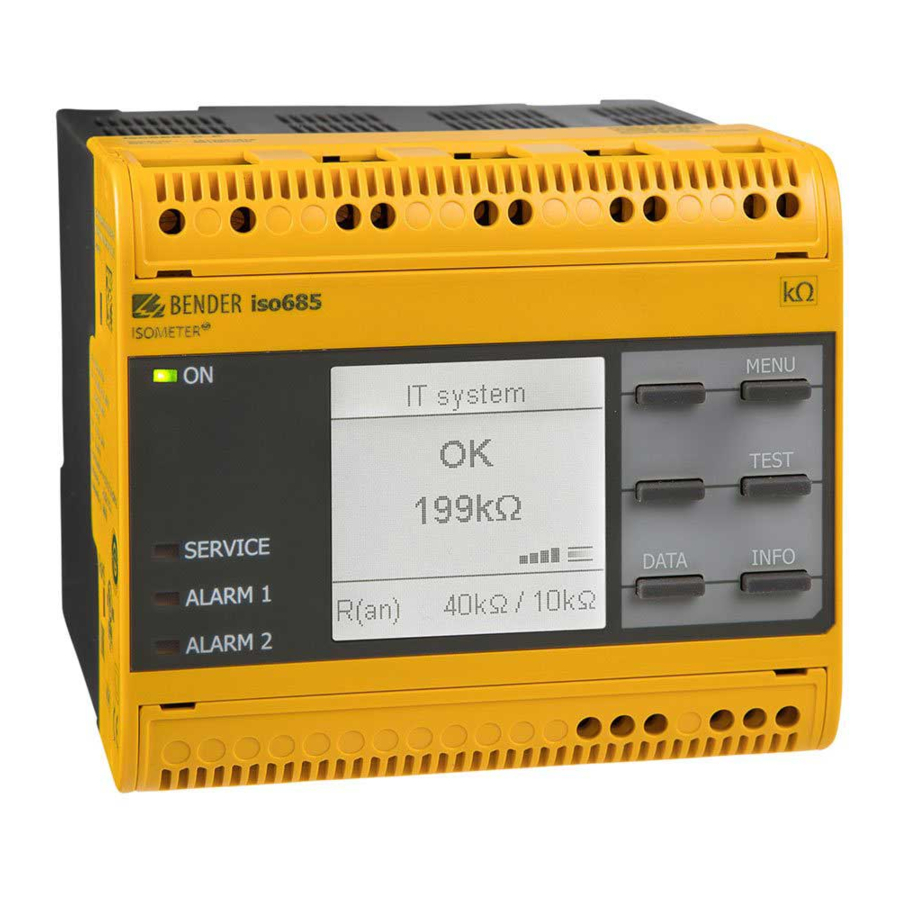
Page 24: Display
8. Display Display 8.1 Standard display 8.2 Fault display (active) During normal operation, the ISOMETER® displays the message "OK" and below, the cur- An active fault is displayed by rently measured insulation resistance. The upper part of the display turns orange and displays the fault message. Depending on the type of fault, the LEDs "ALARM 1", "ALARM 2"... -
Page 25: Fault Display (Inactive)
Display Display 8.3 Fault display (inactive) 8.4 Acknowledging a fault message An inactive fault is indicated by . If several faults have occurred, the number of faults In order to acknowledge the fault message and return to the ISOMETER®'s standard dis- will also be indicated. -
Page 26: Data-Isograph
Display Display 8.6 Data-isoGraph 8.8 Automatic test The isoGraph represents the chronological sequence of the insulation resistance over First, the ISOMETER® performs an automatic test. During the test, the connections to the time. This graphical representation can be displayed over the following time periods: IT system and to earth are tested. -
Page 27: Settings
9. Settings Settings 9.1 Menustructure Device settings 1. Language Alarm settings 1. Insulation alarm 1. Alarm 1 2. Clock 1. Time 2. Alarm 2 2. Format 3. Memory 3. Summer time 4. Date 2. DC Alarm 1. Alarm 5. Format 2. -
Page 28: Settings In The Device Menu
Settings Settings 9.2 Settings in the device menu (1.1.3) Fault memory Automatic reset of inactive faults at the outputs relay 1, relay 2, digital output 1, digital Representation of the menu items in the headings output 2: The settings of the ISOMETER® are explained in the order of the device If a fault becomes inactive, the programmed outputs remain in fault •on menu. -
Page 29: Profile
•3AC Deactivate (1.5) Coupling RS-485 Device I1 I2 Adapt the ISOMETER® to the requirements of Bender coupling devices. For a description high active active about the connection of coupling devices refer to chapter “Coupling devices” . You may select. TEST RESET •none... -
Page 30: (1.9.2) Digital 2
Settings Settings (1.9.1.1) Mode (1.9.3) Digital 3 The operating mode for the digital input can be set to the following values: Refer to “Digital 1”, page 29. An event is carried out on the rising edge of the digital input (low to high). •Active high Deactivation of the ISOMETER®... - Page 31 Settings Settings (1.10.1.3) Function 1 The following parameters can be set. Up to three functions can be assigned to one output. The functions are linked to an OR Function Description operator: The function is not used. •off The status of the output changes when the value falls below the set •Ins.
-
Page 32: (1.10.2) Relais 2
Settings Settings (1.10.1.4) Function 2 Maximalen Ausgangsstrom beachten! Refer to chapter 9.2 (1.10.1.3) “Function 1” on page Maximaler Ausgangsstrom bei interner Spannungsversorgung über A1/+ und A2/-: 200 mA in Summe an X1. (1.10.1.5) Function3 Beachten Sie außerdem die Formel zur Berechnung von I in den LmaxX1 Refer to... - Page 33 Settings Settings (1.10.6.1) Mode Calculation of the insulation resistance using the analogue output: The following values can be set for the operating mode of the analogue output Lower value Upper value ) * R Analogue Output A Analogue Output A 0 mA 20 mA Current output...
-
Page 34: Data Measured Values
Settings Settings (2.0) Data measured values (4.0) History The ISOMETER® stores certain measured values for a specific period of time. You can view In the history menu, the faults detected by the ISOMETER® are displayed. these data in the "Data meas. value" menu. Navigate through the different views using Overview of faults that have occurred. -
Page 35: 5) Format (Date)
Settings Settings (5.2.5) Format (date) (5.3.2.1) DHCP Select the date format that you want to be displayed: Select whether you want to use automatic address assignment via your DHCP server. If the automatic IP address assignment is enabled, the IP address, the subnet mask and the day, month, year •dd.mm.yy standard gateway will be automatically assigned. -
Page 36: (5.3.4) Modbus/Tcp
Alarm LEDs light in the event of an alarm. • off (5.3.5) RS-485 Set the parameters for communication with other devices via the Bender sensor bus. (5.5) Password Use the password function to protect the device parameters against unauthorised adjust- Selecting an RS-485 protocol 1. -
Page 37: (5.6) Commissioning
1. Profile: Enter a 4-digit Service Profile PIN Activation of special customer profiles by Bender. The device is first configured by the Bender service and the configuration is saved in a service profile. Activating this profile causes a warning message. The customer can activate it as a customer-specific profile by entering a Service Profile PIN. -
Page 38: Device Communication
– Easy and fast parameterisation of the device menu item "Allow" must have been set in the "Write access" menu. – Easy assignment and editing options of device texts • Maintenance – Data storage of specific events for fast support by the Bender service isoRW685W-D_D00178_07_M_XXEN/12.2021... -
Page 39: User Interface
Device communication Device communication 10.4.3 User interface 10.4.4 Menu structure The web menu is located on the left side of the browser window. Activated menu items are either highlighted in YELLOW or written in YELLOW. Use the scroll bar on the right side to display further menu items. -
Page 40: Parameter Changes
Device communication Device communication 10.4.5 Parameter changes 10.4.5.3 Error detection in case of incorrect entry In some cases, the system expects certain characters to be entered, for example, CAPITAL 10.4.5.1 Display of parameters in standard versions LETTERS. In case of an incorrect entry, the corresponding field is coloured in RED. Inputs are located horizontally (orange frame) and the corresponding parameters ver- tically (blue frame). -
Page 41: Changing Parameters In The Web Browser
Device communication Device communication 10.4.6 Changing parameters in the web browser 10.4.7 Changing parameters in the device menu when the web browser is open Changed values are highlighted in YELLOW in the input field (see fig. 2.1). Changes can If values are changed in the iso685 device menu, the changed values are not au- be made via drop-down menu, value input or text input. -
Page 42: Bs Bus
The optimum cable routing for the BS bus is a double-terminated bus topology. The The BS bus is used to extend Bender measuring devices (e.g. ISOMETER®) It is an RS-485 in- length of the branch line is limited to 1 m. These branch lines do not have to be terface with a specially developed protocol for Bender devices. -
Page 43: Isodata Protocol
BMS protocol. To evaluate the data by means of a PC or laptop, an USB/RS232-RS485 interface converter are required. Contact Bender Service to receive this device. Interface data: • The RS-485 interface, galvanically isolated from the device electronics •... -
Page 44: Isodata-Protocol Table
Device communication 10.7.1 isoData-protocol table Description Length [Bytes] Value Unit Example string Mode Data packet start character for modes 2 and 3 Data packet start character 0x02 0x02 for mode 1 Available Bitmask Dependent on the fields included. (Bitmask) FFFFFFFF Date Current date dd.mm.yy... - Page 45 Device communication Description Length [Bytes] Value Unit Example string Mode Voltage between phase L2 and PE. Voltage U (VRMS) L2-PE 1234 RMS value, Note: always signed with '+' Voltage between phase L3 and PE. Voltage U (VRMS) L3-PE 1234 RMS value, Note: always signed with '+' Quality of measured value 0 % = Poor quality Measurement quality...
- Page 46 Device communication Description Length [Bytes] Value Unit Example string Mode 0 == No alarm Alarm message Insualtion fault 1 == Alarm 1 Number Brief overview 2 == Alarm 2 3 == Alarm 1 + Alarm 2 Temperature in device Temperature value preceeded by '+' or '-' sign °C +100 System frequency...
-
Page 47: Coupling Devices
11. Coupling devices Coupling devices Coupling devices extend the nominal system voltage range of an ISOMETER®. Behaviour of system: Depending on the configuration, systems up to a nominal system voltage of 12 kV can be • If the ISOMETER® is operated with a coupling device, this device must be specified in monitored. -
Page 48: Connection Using The Agh520S (3Ac)
Coupling devices Coupling devices 11.3 Connection using the AGH520S (3AC) 11.4 Connection using the AGH520S (3(N)AC) Type: AGH520S Type: AGH520S Nominal voltage: AC 0…7200 V Nominal voltage: AC 0…7200 V Operative uncertainty: 15 % min. +/- 5 kΩ Operative uncertainty: 15 % min. +/- 5 kΩ Art.-No.: B 913 033 Art.-No.: B 913 033 isoRW685W-D_D00178_07_M_XXEN/12.2021... -
Page 49: Connection Using The Agh204S-4
Coupling devices Coupling devices 11.5 Connection using the AGH204S-4 11.6 Connection using the AGH676S-4 A) with rectifier B) without rectifier Type: AGH204S-4 Type: AGH676S-4 Nominal voltage with rectifier: AC 0...1300 V Nominal voltage: AC 12 kV Nominal voltage without rectifier: AC 0...1650 V Operative uncertainty: 15 % min. -
Page 50: Alarm Messages
12. Alarm messages 12.1 Measuring value alarms Alarmmeldungen werden direkt nach dem Einschalten aktiviert und können sofort auftreten. Alarm message Description Measures LED indicators • Observe insulation resistance in the monitored system An insulation fault exists. The insulation resistance falls Insulation fault and, if necessary, eliminate fault. - Page 51 • Press the TEST button Device error x.xx Internal device fault • Switch the supply voltage off and on "SERVICE" is lit • Contact Bender Service The device synhronises over a longer period of time. (longer • Restart Synchronizing ... than five minutes)
-
Page 52: Technical Data
– – – – tings. If no settings have been made by the Bender service, the profile has the same parameters as the "Power circuits" profile. For response times, refer „Device profiles“ at the follwing sections. Switching between profiles * Low-frequency system voltages When switching a profile, the value of R is reset. -
Page 53: Diagrams
Technical data Technical data 13.2 Diagrams 13.2.1 Response time profile power circuits 13.2.3 Response time generator profile Response time depending on response value and system leakage capacitance Response time depending on response value and system leakage capacitance acc. to IEC 61557-8 (U = 690 V, f = 50 Hz) measuring range <... -
Page 54: Response Time Inverter > 10 Hz Profile
Technical data Technical data 13.2.5 Response time inverter > 10 Hz profile 13.2.7 Response time DC alarm Response time depending on response value and system leakage capacitance Typical response times DC alarm at R depending on the measurement profile acc. to IEC 61557-8 (U = 690 V, f = 50 Hz) measuring range <... -
Page 55: Factory Settings Iso685-X
Technical data Technical data 13.3 Factory settings iso685-x Parameter Value Parameter Value Switching elements Response values/alarms Relay 1 Test Response value R (ALARM 1) 40 kΩ Operating mode N/C operation Response value R (ALARM 2) 10 kΩ Function 1 Ins. alarm 1 DC alarm Function 2 Connection fault... -
Page 56: Tabular Data Isorw685W-D
Technical data Technical data 13.4 Tabular data isoRW685W-D Supply via X1: Supply voltage U ....................................DC 24 V Insulation coordination acc. to IEC 60664-1/IEC 60664-3 Tolerance of U ................................DC -20…+25 % Definitions: IT system being monitored Measuring circuit (IC1)..............................(L1/+, L2, L3/-) Nominal system voltage range U ...................... - Page 57 Technical data Technical data ON (operation LED) ....................................green Interfaces SERVICE......................................yellow Field bus: ALARM 1......................................yellow Interface/protocol............................web server/Modbus TCP/BCOM ALARM 2......................................yellow Data rate................................10/100 Mbit/s, autodetect Max. amount Modbus requests ..............................< 100/s Inputs/outputs (X1-Interface) Cable length ....................................≤ 100 m Cable length X1 (unshielded cable) ..............................
-
Page 58: Standards And Certifications
Technical data Technical data Environment/EMC and temperature ranges Other EMC ..............................DIN EN 50121-3-2, IEC 61326-2-4 Operating mode................................continuous operation Operating temperature................................-40…+70 °C Mounting position (0°)................display-oriented, cooling slots must be ventilated vertically Transport....................................-40…+85 °C Degree of protection internal components ............................IP40 Long-term storage ................................-40…+70 °C Degree of protection terminals ................................IP20 Classification of climatic conditions acc. -
Page 59: Ordering Details Isorw685W-D
13.6 Ordering details isoRW685W-D 13.7 Glossary BB bus The BB bus is an interface which enables Bender devices to communicate 13.6.1 Device with each other (Bender-internal device bus). The BB bus can be used with an ISOMETER® and one or more EDS44…-S. - Page 60 Londorfer Straße 65 • 35305 Grünberg • Germany Carl-Benz-Straße 8 • 35305 Grünberg • Germany Tel.: +49 6401 807-0 Tel.: +49 6401 807-760 Fax: +49 6401 807-259 Fax: +49 6401 807-629 E-Mail: info@bender.de E-Mail: info@bender-service.com Web: www.bender.de Web: http://www.bender.de Group Fotos: Bender Archiv und bendersystembau Archiv.
Need help?
Do you have a question about the ISOMETER isoRW685W-D and is the answer not in the manual?
Questions and answers