
Subscribe to Our Youtube Channel
Related Manuals for Creative Play THE CAPTAIN


Summary of Contents for Creative Play THE CAPTAIN
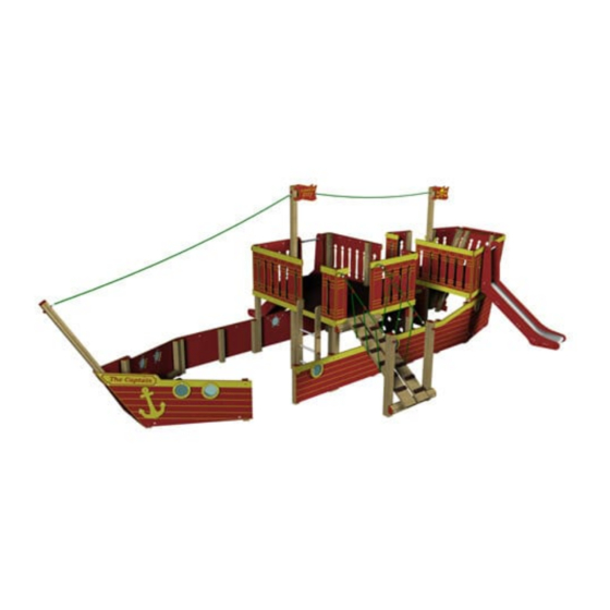
- Page 1 THE CAPTAIN Installation Instructions VOY122 - QUARTER MASTER VOY121 - FIRST MATE REF: VOY123 - THE CAPTAIN pg 1 of 53...
-
Page 2: Parts Required
PARTS required PARTS required BOW Timbers CODE TYPE SIZE VOY121-B1 90x90 2700 VOY121-B VOY121-B3 (ASSEMBLY) ASSEMBLY BOW Pre-assembled parts STARBOARD FRONT (BOW PANEL) (BOW PANEL) PORTSIDE STAIRS (BOW PANEL) (BOW) REF: VOY123 - THE CAPTAIN pg 2 of 53... - Page 3 (FM180 WOOD SCREWS) (M12 x 130* CUP SQUARE BOLTS) (COVERED END) (M12 NYLOCS) ENTRY ‘OPEN BACK’ Pre-assembled parts PORTSIDE STARBOARD (ENTRY PANEL) (ENTRY PANEL) ENTRY ‘OPEN FRONT’ fixings (FM80 WOOD SCREWS) REF: VOY123 - THE CAPTAIN pg 3 of 53...
- Page 4 MAIN DECK Timbers VOY123-M VOY123-M VOY123-M VOY123-M VOY123-M VOY123-M VOY123-M VOY123-M VOY123-M VOY123-M VOY123-M LADDER ASSEMBLY GANGPLANK ASSEMBLY MAIN DECK Pre-assembled parts PANELa PANELb PANELc/f (MAIN DECK) (MAIN DECK) (MAIN DECK) REF: VOY123 - THE CAPTAIN pg 4 of 53...
- Page 5 PARTS required MAIN DECK Pre-assembled parts PANELd PANELe (MAIN DECK) (MAIN DECK) PANELg PANELh (MAIN DECK) (MAIN DECK) 1.2m SLIDE GANGPLANK (MAIN DECK) (MAIN DECK) REF: VOY123 - THE CAPTAIN pg 5 of 53...
- Page 6 (FM80 WOOD SCREWS) (M12 x 230* CUP SQUARE BOLTS) (FM120 WOOD SCREWS) (M12 x 290* CUP SQUARE BOLTS) (Polyfix halves) INC POLYFIX HALF SCREWS (M12 NYLOCS) (M10 NYLOCS) (COVERED END) REF: VOY123 - THE CAPTAIN pg 6 of 53...
- Page 7 PORTSIDE STARBOARD (BACK PANEL) (BACK PANEL) STERN Timbers VOY121-S VOY121-S VOY121-S VOY121-S VOY121-S S10b VOY121-S VOY121-S PANELh ASSEMBLY PANELh ASSEMBLY PANELc ASSEMBLY PANELc ASSEMBLY PANELe ASSEMBLY VOY121-S PANELc ASSEMBLY VOY121-S S10a REF: VOY123 - THE CAPTAIN pg 7 of 53...
- Page 8 PARTS required STERN Pre-assembled parts PANELb PANELa PANELc (STERN) (STERN) (STERN) PANELg PANELf PANELh (STERN) (STERN) (STERN) STERN PANELi REAR STERN PANELj REAR PANELi / PANELj 1.0m SLIDE (STERN) (STERN) REF: VOY123 - THE CAPTAIN pg 8 of 53...
- Page 9 PARTS required STERN Pre-assembled parts PANELd PANELe (STERN) (STERN) Starboard Portside SHIPS WHEEL FLAG (STERN) NET CLIMBER END COVER (STERN) (STERN) REF: VOY123 - THE CAPTAIN pg 9 of 53...
- Page 10 (M12 x 120* CUP SQUARE BOLTS) (M12 x 130* CUP SQUARE BOLTS) (M12 x 220* CUP SQUARE BOLTS) (COVERED END) (M12 NYLOCS) HEXA GRIP MAIN DECK -H1 MAIN DECK -H2 BOW-H1 BOW-H2 REF: VOY123 - THE CAPTAIN pg 10 of 53...
- Page 11 PARTS required HEXA GRIP STERN-H1 STERN-H2 STERN-H3 INDIVIDUAL ROPES RIGGING ROPE RIGGING ROPE REF: VOY123 - THE CAPTAIN pg 11 of 53...
-
Page 12: Tools Required
ADDITIONAL Fixings (FM120 WOOD SCREWS) (COVERED END) (M12 NYLOCS) (FM180 WOOD SCREWS) TOOLS required REF: VOY123 - THE CAPTAIN pg 12 of 53... -
Page 13: Foundation Details
Use a 500mm x 400mm Foundation when a post SHARES the same hole foundation for ‘standard’ upright for angled posts - ENSURE 500mm posts starts from the timber edge (rather than centre of the post) REF: VOY123 - THE CAPTAIN pg 13 of 53... - Page 14 S10b STAIRS S10a Y 1055mm PLAN VIEW...
- Page 15 FOUNDATION Details POST LOCATIONS REF: VOY123 - THE CAPTAIN pg 15 of 53...
- Page 16 ADDITIONAL ITEMS Y 1055mm NET CLIMBER 1.2m SLIDE DATUM POINT LADDER NOTES: The NET GROUND ANCHOUR needs to sit 1.0m SLIDE 5-10mm below FINISHED GROUND LEVEL LADDER 1.0m SLIDE NET CLIMBER REF: VOY123 - THE CAPTAIN pg 16 of 53...
-
Page 17: Surfacing Details
= SURFACE AREA 4915 3891 2624 2629 1682 1952 2624 3912 3930 4646 Y 1055mm NOTES: The stern slide ‘OUTLINE’ has been included to help highlight the orientation of the area REF: VOY123 - THE CAPTAIN pg 17 of 53... - Page 18 SURFACING Details OVERALL AREA - DATUM POINT = MINIMUM SPACE = SURFACE AREA REF: VOY123 - THE CAPTAIN pg 18 of 53...
-
Page 19: Section 1 - Bow Assembly
Position the BOW PANELS - Starboard / Portside DRY INSTALL - Do not concrete posts until the full assembly is complete Ensure The PANELS are positioned 30mm above FINISHED GROUND LEVEL REF: VOY123 - THE CAPTAIN pg 19 of 53... - Page 20 Using 4 x FM180 WOOD SCREWS ASSEMBLY Ensure LOCATION HOLES line up Circled BELOW RIGHT - these holes are to locate assembly only Notes Screw either side of the LOCATION HOLES REF: VOY123 - THE CAPTAIN pg 20 of 53...
- Page 21 Using 1 x M12x130 CUP SQUARE BOLT / 1 x M12 x 120 CUP SQUARE BOLT / 2 x M12 NYLOCS / 1 x COVERED END M12x130 CUP SQUARE BOLT COVERED END NOT REQUIRED M12x120 CUP SQUARE BOLT Position & attach the FRONT assembly Using 1 x FM80 WOOD SCREW REF: VOY123 - THE CAPTAIN pg 21 of 53...
- Page 22 Using 4 x FM 180 WOOD SCREWS Notes The TOP STEP marked red - needs to sit 18mm above the face of the timber - this will level with the HEXA GRIP FLOOR REF: VOY123 - THE CAPTAIN pg 22 of 53...
- Page 23 Attach the HEXA GRIP BOW-H1 Using 4 x FM 80 WOOD SCREWS / 4 x FM180 WOOD SCREWS Notes Use the FM180 in the locations circled below (remaining will be FM80) BOW ASSEMBLY - COMPLETE REF: VOY123 - THE CAPTAIN pg 23 of 53...
-
Page 24: Section 2 - Entry
DRY INSTALL - Do not concrete posts until the full assembly is complete Ensure The PANELS are positioned 30mm above FINISHED GROUND LEVEL Attach the Starboard ENTRY PANEL to the BOW Using 2 x FM80 WOOD SCREWS REF: VOY123 - THE CAPTAIN pg 24 of 53... -
Page 25: Section 3 - Main Deck
VOY123-M VOY123-M Notes M1 timber has a foundation of 450mm circled above All other main timber uprights have foundations of 750mm (below finished ground level) M12x290 CUP SQUARE M12x200 CUP SQUARE REF: VOY123 - THE CAPTAIN pg 25 of 53... - Page 26 Installation Instructions Position M10 timbers The timbers will be attached when the HEXA GRIP floor is installed VOY123-M VOY123-M VOY123-M REF: VOY123 - THE CAPTAIN pg 26 of 53...
- Page 27 Using 12 x FM80 WOOD SCREWS (6 for each panel) PANELc (MAIN DECK) PANELf (MAIN DECK) Ensure panels are positoned correctly Ensure The PANELS are positioned 30mm above FINISHED GROUND LEVEL REF: VOY123 - THE CAPTAIN pg 27 of 53...
- Page 28 Attach timber M5 to Using 2 x M12x200 CUP SQUARE BOLT / 2 x M12 NYLOCS / 2 x COVERED END VOY123-M VOY123-M VOY123-M Attach PANELg Using 4 x PLAYTEC L’s REF: VOY123 - THE CAPTAIN pg 28 of 53...
- Page 29 Installation Instructions Attach PANELg & PLAYTEC L’s Using 18 x FM80 WOOD SCREWS looking towards the BOW looking towards the STERN Attach PANELd Using 14 x FM80 WOOD SCREWS REF: VOY123 - THE CAPTAIN pg 29 of 53...
- Page 30 BOW Attach PANELe Using 11 x FM80 WOOD SCREWS Notes PANELe (MAIN DECK) DO NOT SCREW / BOLT the panel through the holes circled LEFT (these are for the gangplank ROPES) REF: VOY123 - THE CAPTAIN pg 30 of 53...
- Page 31 Attach the HEXA GRIP MAIN DECK H2 / H1 Using 16 x FM 80 WOOD SCREWS MAIN DECK -H2 MAIN DECK -H1 NOTES: VOY123-M VOY123-M The screws will attach the HEXA GRIP and floor support timbers REF: VOY123 - THE CAPTAIN pg 31 of 53...
- Page 32 Position the 1.2m Main Deck Slide The CUT OUTS in the slide will slot onto / over PANELa (circled below) Attach PANELb Using 8 x FM80 WOOD SCREWS PANELb (MAIN DECK) REF: VOY123 - THE CAPTAIN pg 32 of 53...
- Page 33 fixed LOCKED Position M4 timbers & attach M5 timber Using 2 x M12x230 CUP SQUARE BOLT / 2 x M12 NYLOCS / 2 x COVERED END VOY123-M VOY123-M VOY123-M REF: VOY123 - THE CAPTAIN pg 33 of 53...
- Page 34 PLEASE ENSURE M10 NYLOCS are used for the EYEBOLT fixings on the net Attach the GANGPLANK ‘boards’ to the M5 timbers Using 8 x FM120 WOOD SCREWS ENSURE: Spacing between boards is CORRECT REF: VOY123 - THE CAPTAIN pg 34 of 53...
- Page 35 Attach the net to the GANGPLANK timbers Using 12 x POLYFIX HALVES (and screws supplied with the HALVES) Attach the LADDER Using 4 x FM80 WOOD SCREWS NOTES: COUNTERSINK the holes circled below - BEFORE screwing REF: VOY123 - THE CAPTAIN pg 35 of 53...
- Page 36 Installation Instructions Attach CP FLAG Using 4 x FM80 WOOD SCREWS MAIN DECK ASSEMBLY - COMPLETE REF: VOY123 - THE CAPTAIN pg 36 of 53...
-
Page 37: Section 4 - Back Panels
DRY INSTALL - Do not concrete posts until the full assembly is complete Ensure The PANELS are positioned 30mm above FINISHED GROUND LEVEL Attach ADJOINING timber Using 6 x FM120 WOOD SCREWS (3 each side - circled below RIGHT) REF: VOY123 - THE CAPTAIN pg 37 of 53... -
Page 38: Section 5 - Stern
VOY121-S VOY121-S VOY121-S VOY121-S S10b Further secure the panel to the timbers Using 6 x FM80 WOOD SCREWS (locations circled below) Ensure The PANELS are positioned 30mm above FINISHED GROUND LEVEL REF: VOY123 - THE CAPTAIN pg 38 of 53... - Page 39 Using 2x M12x130 CUP SQUARE BOLT / 2 x M12 x 120 CUP SQUARE BOLT / 4 x M12 NYLOCS / 4 x COVERED END VOY121-S VOY121-S S10a Further secure the panel to the timbers Using 2 x FM80 WOOD SCREWS (locations circled below) Ensure The PANELS are positioned 30mm above FINISHED GROUND LEVEL REF: VOY123 - THE CAPTAIN pg 39 of 53...
- Page 40 Using 2x M12x130 CUP SQUARE BOLT / 4 x M12 x 120 CUP SQUARE BOLT / 6 x M12 NYLOCS / 6 x COVERED END VOY121-S STERN PANELi REAR VOY121-S STERN PANELj REAR Further secure the panels to the timbers Using 6 x FM80 WOOD SCREWS (locations circled below) REF: VOY123 - THE CAPTAIN pg 40 of 53...
- Page 41 The timbers will be attached when the HEXA GRIP floor is installed VOY121-S VOY121-S PANELh (STERN) PANELc (STERN) Position timber S1 x 2 As per STEP 6 - The timbers will be attached when the HEXA GRIP floor is installed VOY121-S VOY121-S REF: VOY123 - THE CAPTAIN pg 41 of 53...
- Page 42 Attach PANEL i / j assembly to timbers S4a / S4b Using 14 x FM80 WOOD SCREWS VOY121-S VOY121-S Ensure The top face of the four back timbers MUST BE LEVEL - highlighted red left REF: VOY123 - THE CAPTAIN pg 42 of 53...
- Page 43 Position & Attach timber S13 and PANELd (stern) Using 1 x M12 x 220 CUP SQUARE BOLT / 1 x M12 NYLOCS / 1 x COVERED END / 11 x FM80 WOOD SCREWS VOY121-S PANELd (STERN) REF: VOY123 - THE CAPTAIN pg 43 of 53...
- Page 44 The panel will SLOT BEHIND the yellow cover strip on the lower panel - circled right Position the 1m Stern Slide The CUT OUTS in the slide will slot onto / over PANELb (circled below) REF: VOY123 - THE CAPTAIN pg 44 of 53...
- Page 45 Using 2 x FM 80 WOOD SCREWS (circled below) NOTES: With PANELa / PANELb attached the postion of the slide will be LOCKED ENSURE: Slide has NO movement and is securely fixed REF: VOY123 - THE CAPTAIN pg 45 of 53...
- Page 46 Attach PANELe (Stern) - CLIMBING PANEL Using 1 x M12 x 120 CUP SQUARE BOLT / 1 x M12 NYLOCS / 1 x COVERED END / 1 x FM80 WOOD SCREW REF: VOY123 - THE CAPTAIN pg 46 of 53...
- Page 47 PANELe that is NOT bolted (view shown right is looking from the REAR of the ship) Attach the NET CLIMBER Using 3 x M12 NYLOCS / 3 x COVERED END (the ground anchor is PRE-ATTACHED) REF: VOY123 - THE CAPTAIN pg 47 of 53...
- Page 48 Installation Instructions Attach additional parts to the STERN Using 14 x FM 80 WOOD SCREWS (4 for FLAG / 8 for END COVER / 2 for SHIPS WHEEL) STERN ASSEMBLY - COMPLETE REF: VOY123 - THE CAPTAIN pg 48 of 53...
- Page 49 Installation Instructions SECTION VIEW of THE CAPTAIN Check dimensions as shown below SECTION VIEW A-A REF: VOY123 - THE CAPTAIN pg 49 of 53...
- Page 50 Attach RIGGING ROPE to the B1 / M1 / S13 timbers Using 4 x M12 NYLOCS / 4 x COVERED END Attach ADJOINING timbers - STERN to BACK Using 6 x FM180 WOOD SCREWS (3 each side - circled below RIGHT) REF: VOY123 - THE CAPTAIN pg 50 of 53...
- Page 51 Installation Instructions Attach ADJOINING timbers - OPEN FRONT to MAIN DECK Using 6 x FM120 WOOD SCREWS (3 each side - circled below LEFT) REF: VOY123 - THE CAPTAIN pg 51 of 53...
- Page 52 Addition Drawings PLAN VIEW SIDE VIEW REF: VOY123 - THE CAPTAIN pg 52 of 53...
- Page 53 Notes: This space can be used to make any notes relating to installation / assembly of the CAPTAIN - pass this sheet back to PRODUCT DEVELOPMENT to review the notes REF: VOY123 - THE CAPTAIN pg 53 of 53...
Need help?
Do you have a question about the THE CAPTAIN and is the answer not in the manual?
Questions and answers