Table of Contents
Advertisement
Quick Links
Advertisement
Table of Contents

Summary of Contents for GRAUPNER HoTT GR-18
-
Page 1: User Manual
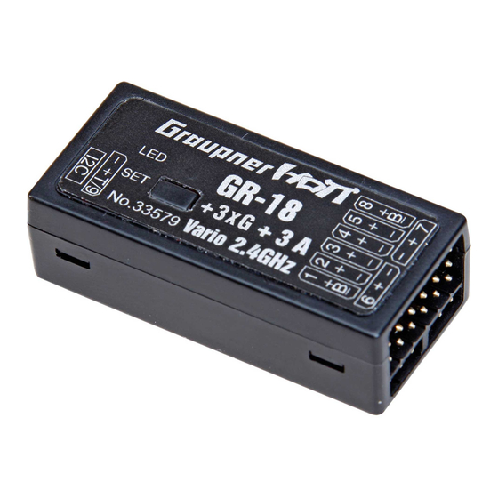
User manual HoTT GR-18 receiver with Copterfirmware No. 33579... -
Page 2: Table Of Contents
Index Index .................. 2 Introduction ................ 3 Service centre ..............3 Package content ..............3 Intended use ..............4 Technical Data ..............4 Installation in the model (Copter) ......... 6 Binding ................6 Connections ............... 7 Receiver setting menu ............7 Gyro initialization .............. -
Page 3: Introduction
INNOVATION & TECHNOLOGIE Introduction Thank you very much for choosing a Graupner HOTT GYRO RECEIVER. This receiver is extremely versatile. Read this manual carefully to achieve the best results with your receiver and first of all to control safely your model. If you experience any trouble during operation, take the instructions to help or ask your dealer or Graupner Service Centre. -
Page 4: Intended Use
For any improper use no warranty or liability is ac- cepted. Read through this entire manual before you attempt to program or set the receiver. Graupner/SJ constantly works on the development of all prod- ucts; we reserve the right to change the item, its technology and equipment. - Page 5 / or modification of the product is not permitted. Ð They may only be used our recommended components and accessories. Use only genuine matching Graupner con- nectors of the same design and the same material. Ð Make sure that all connections are secure. Do not pull on the cables when you unplug the connector.
-
Page 6: Installation In The Model (Copter)
Ð Protect the receiver from dust, dirt, moisture and other for- eign parts. Do not expose this equipment to vibration and excessive heat or cold. The remote control operation may be carried out only in “normal” ambient temperatures, in a range from -10 °... -
Page 7: Connections
negative wire (-) is brown, the positive (+) red and the signal orange. The servo sockets of Graupner HoTT 2.4 receivers are numbered sequentially. The socket for channel 8 (K6 in GR 18) can also be programmed to deliver a (digital) sum signal (see next section). -
Page 8: Gyro Initialization
Maximum altitude (Max. altitude) Inform yourself before flying your model on which maximum alti- At this point you can enter a maximum altitude, at which an tude you can fly in the uncon- alarm is triggered, either via the transmitter’s RF module in the trolled airspace over the starting form of the “general alarm tone”: a regular beeping at a rate of position and do not exceed it. -
Page 9: Transmitter Pre-Setting
INNOVATION & TECHNOLOGIE Transmitter pre-setting Step 1: Setting the flight mode - Attitude or In the transmitter it must be selected a free model memory, Rate mode the model type must be “surface model“ and the channel 1 direction must be set so that in “motor off“ position the power indicator must show -100%. -
Page 10: Axis Assignment
sequence this parameter has to gas curve, will be explained in next section. MINPOWER % The setting is principally used to prevent the motors shut down in flight. Adjust so that the motors are running straight. Under no circumstances unnecessarily high set, this would limit the controller possibilities. -
Page 11: Roll And Nick Setting
Copters the value can be 100. If, because of its gravity centre, the Copter is more agile on the Roll axis than on the Nick axis, then you can change here the roll factor. In the Graupner ALPHA RACE 250 Q this value is set about 65%. POWER2SENS.: GR-18_Copter_jh_V1... -
Page 12: Multicopter Yaw Settings
Very strong drives can lead to oscillating at full throttle. This parameter allows you to set a kind of gyro suppression. High- er values result in an increased gyro suppression towards full throttle. Only for attitude mode: ROLL/NICK I: Set the I component of the Attitude mode. At too low values the Copter swings slowly. -
Page 13: Firmware Update
(order no. 7168.6A or 7168.S), which are available separately. The programs and files required can be found in the Down- load area for the corresponding products at www.graupner.de. Connect the adapter lead to the USB interface (order no. 7168.6). The connectors are reverse polarity protected: note the small chamfers on the sides. - Page 14 The receiver LED lights up red and green during this pro- cess and flashes red and green alternately once the transfer is complete. Please refer to the detailed update instructions for the item in question in the Download area at www.graupner.de. GR-18_Copter_jh_V1...
-
Page 15: Declaration Of Conformity
Measures for the efficient use of the radio frequency spectrum § 3 (2) (Article 3 (2)) Kirchheim, 07. Mai 2015 Ralf Helbing, Geschäftsführer Ralf Helbing, Managing Director Graupner/ SJ GmbH Henriettenstraße 96 D-73230 Kirchheim/Teck Germany Tel: 07021/722-0 Fax: 07021/722-188 EMail: info@graupner.de... -
Page 16: Notes For Environmental Protection
The current version can be found on the Internet at www. graupner.de on the relevant product page. In addition, the company Graupner/SJ GmbH has no responsibility or liability for any errors or inaccuracies that may appear in construction or operation manuals.


Need help?
Do you have a question about the HoTT GR-18 and is the answer not in the manual?
Questions and answers