Table of Contents
Advertisement
Quick Links
Advertisement
Table of Contents

Related Manuals for GRAUPNER GR-12L


Summary of Contents for GRAUPNER GR-12L
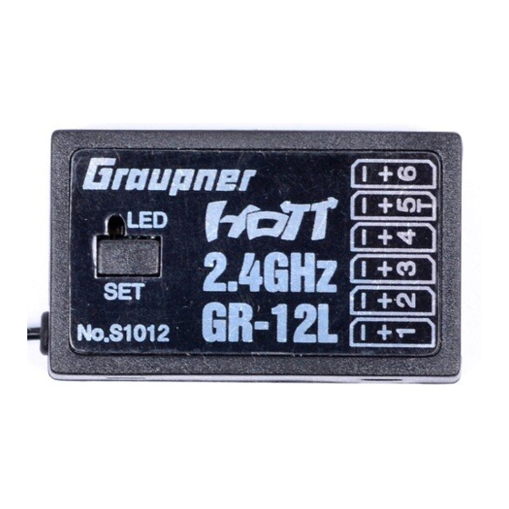
- Page 1 Manual GR-12L HoTT 6 channel 2.4 GHz HoTT receiver No. S1012...
- Page 2 2 / 20 S1012_GR-12L_DE_V1sh...
-
Page 3: Table Of Contents
Service centre ...................4 Intended use ..................5 Target group ..................5 Package content ................5 Technical data ...................6 S1012 GR-12L HoTT ................6 table ................6 Symbol descrip ................7 Safety notes ..................7 For your safety by handling the transmi er and the receiver ..8 For your safety by handling the ba eries ........8... -
Page 4: Intr
Intr Thank you very much for purchasing a Graupner S1012 GR-12L receiver. Read this manual carefully to achieve the best results with your HoTT system and rst of all to safely control your models. If you experience any trouble during opera... -
Page 5: Intended Use
If you do not have su nt knowledge about dealing with radio-controlled models, please contact an expe- rienced modeler or a model club. Package content Receiver S1012 GR-12L HoTT Manual S1012_GR-12L_DE_V1sh 5 / 20... -
Page 6: Technical Data
Technical data 1 x wire 145 mm Antenna of which Antenna 30 mm Opera voltage (2.5) 3.6 ... 8.4 V Frequency range 2400 ... 2483.5 MHz Modula 2.4 GHz FHSS Number of controls Current consump rox. 70 mAh Temperature range -15 …... -
Page 7: Symbol Descrip
Only use the components and spare parts that we recommend. Always use matching, original Graupner plug-in c the same design and material. Make sure that all of the plug-in c ht. -
Page 8: For Your Safety By Handling The Transmi Er And The Receiver
For your safety by handling the transmi er and the receiver WARNING Also while programming the transmi er, make sure that a con- nected motor cannot accidentally start. Disconnect the fuel sup- ply or drive ba ery beforehand. CAUTION Avoid every kind of short-circuit in all sockets of the transmi er! Risk of re! Use only the suitable connectors. -
Page 9: Installa
Connect the devices that have to be connected to the receiver to the row of sockets on one end of the receiver. The servo c the Graupner-HoTT receiver are numbered. The polarity of the plug-in system cannot be reversed. Do not apply force. -
Page 10: Power Supply
4. Within this lapse start the transmi er-side binding accord- ing to the ins 5. If the red LED of the GR-12L HoTT receiver goes out, the binding process has been completed successfully. Your transmi er/receiver c 10 / 20... -
Page 11: Receiver Reset
If a reset has already been performed on an already-bound receiver and the associated model memory is ve in the switched-on trans- mi er, then the red LED of the receiver GR-12L HoTT should go out and thus signal a correct c to the transmi er. Otherwise the process has to be repeated. -
Page 12: Se Ay Of The Receiver Se
"Telemetry" of the corresponding manual as well as a detailed descrip of the receiver menus on the r ve product page at www.graupner. com on the Internet. Note The values shown in the following display illustra always show the standard values. - Page 13 CH5 FUNCTION SERVO Port "5" is suitable for opera RC components and for receiver updates. SENSOR Port 5 is suitable for the opera telemetry sensors. BATT V A er switching as described before, a DC voltage o max. 25,5 V can be displayed instead of the receiver voltage.
-
Page 14: Display "Mixer
With this RSSI signal and a ht control board with OSD, e.g. No. 48377, the signal strength of the receiver can be displayed in video goggles or monitors. Adjustment range: OFF, CH8, CH12, CH16 F.RESET A er changing the value to "Yes"... -
Page 15: Display "Ch Reverse
Display "CH REVERSE" In this display, the dir of rota of each of the servos con- nected to the receiver outputs 1 ... 6 can be set individually: select the desired line; press or tap on the ENTER key or equivalent, then change the se value from "Normal"... -
Page 16: Firmware Update
Do not use force, the plug should click into place easily. Connect the other end of the adapter lead to the socket of the receiver GR-12L HoTT labelled with "-+5T". The polarity of the plug-in system cannot be reversed. Do not apply force. The plug should be fully inserted. - Page 17 S1012_GR-12L_DE_V1sh 17 / 20...
-
Page 18: Simplified Declaration Of Conformity
Manufaturer / Manufakturer GRAUPNER Co. Ltd Post Code: 14557 202-809, 18, Bucheon-ro 198beon-gil, Bucheon-si, Gyeonggi-do, South Korea Vertrieb Deutschland, Österreich, Niederlande D-Power Modellbau Robbe Modellsport Inhaber: Horst Derkum Sürther Straße 92-94 Industriestraße 10 50996 Köln 4565 Inzersdorf im Kremstal Deutschland Österreich... -
Page 19: Notes On Environmental Prot
The current version can be found on the Internet at www.graupner.com on t- th relevant product page. In the company Graupner has no responsibility or liability for any errors or inaccuracies that may...
Need help?
Do you have a question about the GR-12L and is the answer not in the manual?
Questions and answers