
Related Manuals for Wilson Electronics WeBoost Drive Reach Flex Fleet


Summary of Contents for Wilson Electronics WeBoost Drive Reach Flex Fleet
- Page 1 Installation Guide ® Drive Reach Flex Fleet Professional Vehicle Cell Signal Booster Kit...
-
Page 2: Table Of Contents
Index Package Contents . . . . . . . . . . . . . . . . . . . . . . . . . . . . . . . . . . . . . . . . . . . . . . . . . . . . . . . . . . . 1 STEP 1 Mount the Outside Antenna . -
Page 3: Package Contents
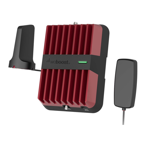
Package Contents Booster & In-Vehicle Power Supply, Outside NMO Antenna Mounting Antenna Hardwire Power + Magnet NMO Mount Bracket Supply & In-line with 14 ft . Cable Fuse Holder Mounting Plate O-Ring Lubricant for Aluminum Packet Vehicle... -
Page 4: Step 1 Mount The Outside Antenna
STEP 1 Mount the Outside Antenna Identify a location for NMO outside antenna on the top of your vehicle that is: ■ Near the center of the roof ■ At least 12 inches away from any other antennas ■ At least 6 inches away from any windows (for best performance install on top of vehicle) Do a soft install before finalizing the antenna... - Page 5 (STEP 1 cont .) Once the antenna location point has been apply silicone identified, route the cable into the vehicle . grease The cable is strong enough that it may be shut in most vehicle doors without damage or the cable can be routed into the vehicle through the third brake, as shown .
- Page 6 (STEP 1 cont .) After running cable through third brake light to into vehicle, pull down the headliner so the cable can be routed into side trim the vehicle cabin . Route the cable down panel the vehicle pillar to the desired booster location .
-
Page 7: Step 2 Mount The Inside Antenna
STEP 2 Mounting the Inside In-Vehicle Antenna Antenna Identify a place to mount the in-vehicle antenna, either on the side of the seat or on the dash and mount . The location should be at least 18 inches but no more than 36 inches from where the cellular device will be used . -
Page 8: Step 3 Hardwiring To Power
STEP 3 Hardwiring to Power The Drive Reach Flex Fleet kit includes a CLA and Hardwire power option . The CLA power can be connected to a vehicle cigarette lighter port . Hardwire instructions are below . Use the steps below as a general template for wiring the power. There are multiple options for wiring and steps will vary depending on the vehicle type. - Page 9 (STEP 3 cont .) ■ Connecting the power supply . Once you have determined a fuse slot to use connect the positive lead on the power cable to the included in-line fuse then attach to a fuse tap and crimp into place (fuse tap is not included in the kit and will vary by vehicle type) .
-
Page 10: Step 4 Connect Coax Cables To Booster
STEP 4 Connect Coax Cables to Booster Connect the cable from the Outside Antenna from Outside Antenna to the port labeled “Outside Antenna” on the booster and connect the cable from the Inside Antenna to the port labeled “Inside Antenna” on the booster . -
Page 11: Step 5 Connect Power Supply To Booster
STEP 5 Connect Power Supply to Booster Connect the 12V Power Supply Cord to the end of the Booster, labeled "12V DC" then plug the power adapter into vehicle’s 12V DC Power Supply . Push switch to ON position . If your Drive Reach is working correctly, the light on the Booster will be green . -
Page 12: Booster Light Patterns
Booster Light Patterns SOLID GREEN This indicates that your Drive Reach Booster is functioning properly and there are no issues with installation . SOLID RED Band has shutoff . This is due to a feedback loop condition called oscillation . This is a built in safety feature that causes a band to shut off to prevent harmful interference with a nearby cell tower . - Page 13 (Booster Light Patterns cont .) NOTE: The signal booster can be reset by disconnecting and reconnecting the power supply . After troubleshooting you must initiate a new power cycle by disconnecting and then reconnecting power to the booster .
-
Page 14: Troubleshooting
Troubleshooting FIXING BLINKING OR RED LIGHT ISSUES This section is only applicable if the Booster is red or blinking red and you are not experiencing the desired signal boost. ■ Unplug the booster’s power supply . ■ Relocate the inside and outside antenna further from each other . The objective is to increase the separation distance between them, so that they will not create this feedback condition discussed before . - Page 15 (Troubleshooting cont .) FREQUENTLY ASKED QUESTIONS How can I contact customer support? Customer Support can be reached Monday through Friday by calling 866 .294 . 1 660, or through our support site at support . w eboost .com . Why do I need to create distance between the Outside Antenna and Inside Antenna? Antennas connected to a booster create spheres of signal .
-
Page 16: Safety Guidelines
Safety Guidelines Use only the power supply provided in this package . Use of a non-weBoost product may damage your equipment . Connecting this signal booster directly to the cell phone with use of an adapter will damage the cell phone . RF Safety Warning: Any antenna used with this device must be located at least 8 inches from all persons . - Page 17 (Safety Guidelines cont .) FOR MORE INFORMATION ON REQUIREMENTS SET OUT IN ISED CPC-2-1-05, SEE BELOW: http://www .ic .gc .ca/eic/site/smt-gst .nsf/eng/sf08942 .html FOR MORE INFORMATION ON REGISTERING YOUR SIGNAL BOOSTER WITH YOUR WIRELESS PROVIDER, PLEASE SEE BELOW: T-Mobile/MetroPCS: https://www . t -mobile .com/support/coverage/register-a-signal-booster Verizon Wireless: https://www .
-
Page 18: Antenna Info
Antenna Info The following accessories are certified by the FCC to be used with the Drive Reach Booster . This radio transmitter 4726A-460061 has been approved by innovation, Science and Economic Development Canada to operate with the antenna types listed below, with the maximum gain indicated . Antenna types not included in this list that have a gain greater than the maximum gain indicated for any type listed are strictly prohibited for use with this device . -
Page 19: Specifications
Specifications Drive Reach Cell Signal Booster 460061 Model PWO460061 4726A-460061 Connectors SMB-Jack Antenna Impedance 50 Ohms Frequency 698-716 MHz, 728-756 MHz, 777-787 MHz, 824-894 MHz, 1850-1995 MHz, 1710-1755/2110-2155 MHz Power output for single cell 700 MHz B12/17 700 MHz B13 800 MHz B5 1700 MHz B4 1900 MHz B2... -
Page 20: Warranty
2 YEAR WARRANTY weBoost Signal Boosters are warranted for two (2) years against defects in workmanship and/or materials . Warranty cases may be resolved by returning the product directly to the reseller with a dated proof of purchase . Signal Boosters may also be returned directly to the manufacturer at the consumer’s expense, with a dated proof of purchase and a Returned Material Authorization (RMA) number supplied by weBoost . - Page 21 Notes 1 .866 .294 . 1 660 www .wilsonelectronics.com support@wilsonelectronics .com...
- Page 22 Notes 1 .866 .294 . 1 660 www .wilsonelectronics.com support@wilsonelectronics .com...
- Page 23 Notes 1 .866 .294 . 1 660 www .wilsonelectronics.com support@wilsonelectronics .com...
- Page 24 .weboost .com or www .weboost .ca support@weboost .com Copyright © 2021 weBoost . All rights reserved . Wilson Electronics products covered by U .S . patent(s) and pending application(s) For patents go to: weboost .com/us/patents NOT AFFILIATED WITH WILSON ANTENNA...
Need help?
Do you have a question about the WeBoost Drive Reach Flex Fleet and is the answer not in the manual?
Questions and answers