
Related Manuals for Wilson Electronics weboost 472061


Summary of Contents for Wilson Electronics weboost 472061
- Page 1 Installation Guide ® Drive Reach Overland Cellular Signal Booster Use our weBoost App to guide you through the installation. See inside page for more details.
- Page 2 Download the weBoost App Download the weBoost App Use our app to guide you through setting up a weBoost cell phone signal booster in your home, business, or vehicle. Boost every network, including 5G, right away. Videos to guide you Antenna positioning guide Before and after cell through installation...
-
Page 3: Table Of Contents
Index Package Contents ............1 Installation Overview . -
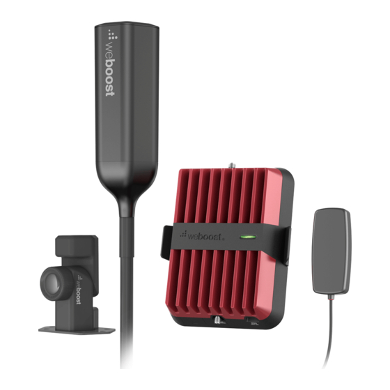
Page 4: Package Contents
Package Contents Drive Reach Signal 13 in. Mast Ext., Inside Outside Antenna, Booster, Bracket & Side-Exit Adapter, Spring Antenna 14 ft. Cable & Heat Power Supply & Thread Lock Pack Shrink Tubes Overland Mounting Stabilizer Arm & Bracket & Mounting Hardware Zip Ties... - Page 5 Compatible Aftermarket Accessories 952315 - 18 ft. Cable for Outside Antenna This cable can be used to add 4 feet to outside antenna. Used for larger ■ vehicles, not recommended unless longer cable is the only option to complete install. 311160 - Desktop Antenna Optional desktop in-vehicle antenna adds flexibility to broadcast boosted ■...
-
Page 6: Installation Overview
Installation Overview Outside Antenna Folding Mount Bracket Stabilizer Inside Antenna Booster to power Use stability arm to secure antenna when laid in the horizontal position. NOTE: System will only fully function with the antenna in the upright position. -
Page 7: Step 1 Assemble The Outside Antenna
STEP 1 Assemble the Outside Outside Antenna Antenna The antenna should be mounted above gear on top of the vehicle. Once you have determined the best location for the outside antenna, insert coax cable 13 in. through mast extension (mast can be mast used optionally), then through cable from... - Page 8 (STEP 1 cont.) Outside Antenna Apply thread locker (provided) to thread points and screw into place. Be sure the outside antenna is the correct height add Thread before applying thread locker. Connect Locker 14-foot cable to outside antenna cable. Heat shrink tube can be applied to the mast connection (optional).
-
Page 9: Step 2 Mounting The Outside Antenna With Overland Mounting Bracket
STEP 2 Mount the Outside Overland Folding Antenna with Overland Mounting Bracket Mounting Bracket This kit includes a folding mounting bracket. This makes it easier to install pull & twist the outside antenna to different types of knob to rotate top portion of overland vehicles. - Page 10 (STEP 2 cont.) secure Outside Antenna to T-Track Mounting Option Mounting Bracket For vehicles with t-track roof rack systems, the provided mounting bracket can be mounted to the roof rack. Use the t-track mounting hardware to secure the bracket to roof rack, then screw in assembled outside antenna.
- Page 11 (STEP 2 cont.) T-Track Mounting Option Outside Antenna in Folded Down horizontal position with Stabilizer Arm The stabilizer arm can be used to secure the outside antenna in the horizontal position. Insert stabilizer Stabilizer Arm arm into t-track, zip tie can be used to in t-track secure it in place.
- Page 12 (STEP 2 cont.) secure Outside Antenna to Mounting Bracket Pole Mounting Option Brackets, hardware and non-slip rubber pad are also provided for securing the folding mounting bracket to 1.0-1.25 inch diameter poles, like roof rails or ladders. ensure knob is pushed in completely after adjusting antenna...
- Page 13 (STEP 2 cont.) Pole Mounting Option Folded Down Stabilizer arm can be used on poles secure with by securing with zip ties, as shown. zip ties tighten zip ties in notches on foot...
- Page 14 (STEP 2 cont.) secure Outside Antenna to Mounting Bracket Fixed Mounting Option The folding mounting bracket can also be secured to a flat surface using the provided hardware as shown here. ensure knob is pushed in completely after adjusting antenna...
- Page 15 (STEP 2 cont.) Route Cable into Vehicle Once the outside antenna is mounted and cable from Outside Antenna secured, route the coax cable into the vehicle. The cable is strong enough that it may be shut in most vehicle doors without damage.
-
Page 16: Step 3 Mounting The Inside Antenna
STEP 3 Mounting the Inside Antenna Identify a place to mount the inside antenna. Mount it either on the side of the seat or on the dash. The antenna should be placed at least 18 inches but no more than 36 inches from where the cellular device will be used. -
Page 17: Step 4 Connect Coax Cables To Booster
STEP 4 Connect Coax Cables to Booster Connect the coax cable from the outside from Outside Antenna antenna to the port labeled “Outside Antenna” on the booster. Then connect the cable from the inside antenna to the port labeled “Inside Antenna”... -
Page 18: Step 5 Connect Power Supply To Booster
STEP 5 Connect Power Supply to Booster Connect the 12V power supply cord to the end of the booster, labeled "12V DC." Then plug the power adapter into vehicle’s 12V DC power supply. Push switch to ON position. If your Drive Reach is working correctly, the light on connect Power the booster will be green. -
Page 19: Booster Light Patterns
Booster Light Patterns SOLID GREEN This indicates that your Drive Reach booster is functioning properly and there are no issues with installation. SOLID RED Band has shutoff. This is due to a feedback loop condition called oscillation. This is a built in safety feature that causes a band to shut off to prevent harmful interference with a nearby cell tower. - Page 20 (Booster Light Patterns cont.) NOTE: The signal booster can be reset by disconnecting and reconnecting the power supply. After troubleshooting, you must initiate a new power cycle by disconnecting and then reconnecting power to the booster.
-
Page 21: Troubleshooting
Troubleshooting FIXING BLINKING OR RED LIGHT ISSUES This section is only applicable if the light on the booster is red or blinking red and you are not experiencing the desired signal boost. 1 Unplug the booster’s power supply. 2 Relocate the inside and outside antenna further from each other. The objective is to increase the separation distance between them, so that they will not create this feedback condition discussed before. - Page 22 (Troubleshooting cont.) FREQUENTLY ASKED QUESTIONS How can I contact customer support? Customer Support can be reached Monday through Friday by calling 1-866-294-1660, or through our support site at support.weboost.com. Why do I need to create distance between the outside antenna and inside antenna? Antennas connected to a booster create spheres of signal.
-
Page 23: Safety Guidelines
Safety Guidelines Use only the power supply provided in this package. Use of a non-weBoost product may damage your equipment. Connecting this signal booster directly to the cell phone with use of an adapter will damage the cell phone. RF Safety Warning: Any antenna used with this device must be located at least 8 inches from all persons. - Page 24 (Safety Guidelines cont.) FOR MORE INFORMATION ON REGISTERING YOUR SIGNAL BOOSTER WITH YOUR WIRELESS PROVIDER IN THE U.S., PLEASE GO TO THE LINK BELOW: https://www.weboost.com/carrier-registration...
-
Page 25: Antenna Info
Antenna Info The following accessories are certified by the FCC to be used with the Drive Reach Booster. This radio transmitter 4726A-460061 has been approved by Innovation, Science and Economic Development Canada to operate with the antenna types listed below, with the maximum gain indicated. Antenna types not included in this list that have a gain greater than the maximum gain indicated for any type listed are strictly prohibited for use with this device. -
Page 26: Specifications
Specifications Drive Reach Cell Signal Booster 460061 Model PWO460061 4726A-460061 SMA-Female Connectors Antenna Impedance 50 Ohms 698-716 MHz, 728-756 MHz, 777-787 MHz, 824-894 MHz, 1850-1995 MHz, 1710-1755/2110-2155 MHz Frequency Power output for single cell 700 MHz B12/17 700 MHz B13 800 MHz B5 1700 MHz B4 1900 MHz B2... -
Page 27: Warranty
2 YEAR WARRANTY weBoost Signal Boosters are warrantied for two (2) years against defects in workmanship and/or materials. Warranty cases may be resolved by returning the product directly to the reseller with a dated proof of purchase. Signal Boosters may also be returned directly to the manufacturer at the consumer’s expense, with a dated proof of purchase and a Returned Material Authorization (RMA) number supplied by weBoost. - Page 28 3301 East Deseret Drive, St. George, UT 1.866.294.1660 www.weboost.com or www.weboost.ca support@weboost.com Copyright © 2022 weBoost. All rights reserved. weBoost products covered by U.S. patent(s) and pending application(s) For patents go to: weboost.com/us/patents GDE000527_Rev02_11.10.22 NOT AFFILIATED WITH WILSON ANTENNA...
Need help?
Do you have a question about the weboost 472061 and is the answer not in the manual?
Questions and answers