
Related Manuals for Baumer GT 7


Summary of Contents for Baumer GT 7
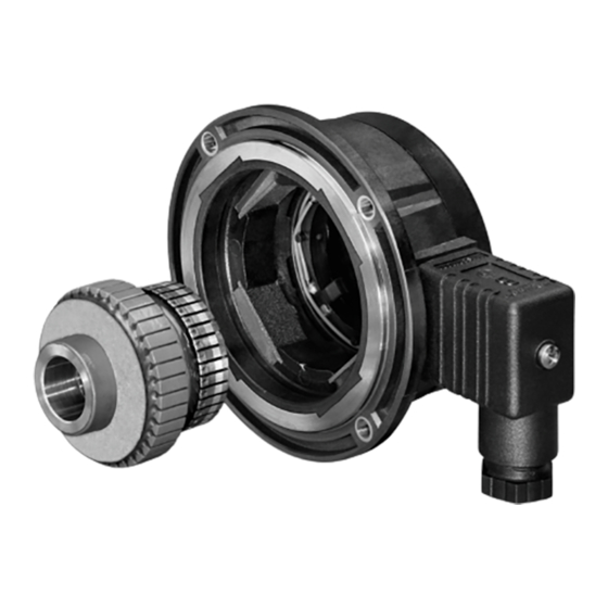
- Page 1 Montage- und Betriebsanleitung Mounting and operating instructions GT 7 Tachogenerator...
-
Page 2: Table Of Contents
Schritt 3 ................................Schritt 4 ................................Schritt 5 ................................Schritt 6 ................................Montagehinweis ............................Abmessungen ................................GT 7.08 mit Schraubklemmenanschluss ..................GT 7.08 mit Anschlusskabel ........................GT 7.16 mit Schraubklemmenanschluss ..................GT 7.16 mit Anschlusskabel ........................Elektrischer Anschluss ............................Schraubklemmenanschluss ........................ - Page 3 ................................... Step 5 ................................... Step 6 ................................... Mounting instruction ..........................Dimensions ................................... GT 7.08 with screw terminal connector ..................... GT 7.08 with connecting cable ......................GT 7.16 with screw terminal connector .................... GT 7.16 with connecting cable ......................Electrical connection ............................
-
Page 4: Allgemeine Hinweise
Hinweis zur Gewährleistung eines einwandfreien Betriebes des Gerätes Information Empfehlung für die Gerätehandhabung Der Tachogenerator GT 7 ist ein generatorisch arbeitendes Prä zi sions-Drehzahl- messgerät, das mit Sorgfalt nur von technisch qualifiziertem Per sonal gehandhabt werden darf. Lebensdauer der Kohlebürsten unter normalen Bedingungen ≥10 Umdrehungen. -
Page 5: General Notes
Informations to ensure correct device operation Information Recommendation for device handling The tachogenerator GT 7 is a generator-based working precision rotary measurement device which must be handled with care by skilled personnel only. Service life of the carbon brushes under normal conditions ≥10 revolutions. -
Page 6: Sicherheitshinweise
Sicherheitshinweise Sicherheitshinweise Verletzungsgefahr durch rotierende Wellen Haare und Kleidungsstücke können von rotierenden Wellen erfasst werden. • Vor allen Arbeiten alle Betriebsspannungen ausschalten und Maschinen stillsetzen. Zerstörungsgefahr durch mechanische Überlastung Eine starre Befestigung kann zu Überlastung durch Zwangskräfte führen. • Die Beweglichkeit des Gerätes niemals einschränken. Unbedingt die Montagehinweise beachten. -
Page 7: Security Indications
Securtiy indications Security indications Risk of injury due to rotating shafts Hair and clothes may become tangled in rotating shafts. • Before all work switch off all voltage supplies and ensure machinery is stationary. Risk of destruction due to mechanical overload Rigid mounting may give rise to constraining forces. -
Page 8: Vorbereitung
Vorbereitung / Preparation Vorbereitung Scope of delivery Lieferumfang Scope of delivery Stator Stator Kohlebürsten (4x) Carbon brushes (4x) Anker mit Hohlwelle Armature with hollow shaft Spannelement Clamping element Gewindebuchse mit Schlüsselfläche 22 mm Insert nut with spanner flat 22 mm Abdeckhaube Cover Verschlussstopfen... -
Page 9: Zur Montage Erforderlich (Nicht Im Lieferumfang Enthalten)
Vorbereitung / Preparation Zur Montage erforderlich Required for mounting (nicht im Lieferumfang enthalten) (not included in scope of delivery) Befestigungsschraube M4x10 mm, ISO 4017 Fixing screw M4x10 mm, ISO 4017 Montagekegel (empfohlen), als Zubehör er- Mounting cone (recommended), available as hältlich: Bestellnummer 11056827 accessory: Order number 11056827 Anschlusskabel ø5...9 mm... -
Page 10: Montage
Montage / Mounting Montage Mounting Schritt 1 Step 1 TX 10 22 mm Schritt 2 Step 2 Zul. Anzugsmoment: Max. tightening torque: = 2...3 Nm Ansicht X siehe Abschnitt 5. View X see section 5. * Siehe Seite 5 See page 5 Antriebswelle einfetten. -
Page 11: Schritt 3
Montage / Mounting Schritt 3 Step 3 Zul. Anzugsmoment: Max tightening torque: 7 mm = 3 Nm Schritt 4 Step 4 Litzenposition beachten! Mind the position of the stranded wire! Schritt 5 Step 5 TX 10 * Siehe Seite 5 oder 6 See page 5 or 6 MB126 - 11055737 Baumer_GT7_II_DE-EN (19A1) -
Page 12: Step 6
Montage / Mounting Schritt 6 Step 6 Mit Druckschraube With pressure screw TX 10 13 * 16 mm 12 * Mit Druckschraube 17 mm Wth pressure screw Ansicht Y siehe Abschnitt 6.1. View Y see section 6.1. 15 * * Siehe Seite 5 oder 6 See page 5 or 6 Keine Silikonkabel verwenden. -
Page 13: Montagehinweis
Montage / Mounting Montagehinweis Mounting instruction Wir empfehlen, das Gerät so zu It is recommended to mount the device montieren, dass der Kabelanschluss with cable connection facing down- keinem direkten Wassereintritt ward and being not exposed to water. ausgesetzt ist. MB126 - 11055737 Baumer_GT7_II_DE-EN (19A1) -
Page 14: Abmessungen
Abmessungen / Dimensions Abmessungen Dimensions GT 7.08 mit Schraubklemmenan- GT 7.08 with screw terminal connector schluss (80500, 80529, 80550, 80575) (80500, 80529, 80550, 80575) Ansicht X siehe Abschnitt 4.2. ø14 View X ø15 see section 4.2. ø16 ø14 ø15 Drehrichtung positiv ø16... -
Page 15: Gt 7.16 Mit Schraubklemmenanschluss
Abmessungen / Dimensions GT 7.16 mit Schraubklemmenanschluss GT 7.16 with screw terminal connector (80631, 80650, 80675) (80631, 80650, 80675) Ansicht X siehe Abschnitt 4.2. ø12 View X ø14 see section 4.2. ø15 ø16 ø12 ø14 ø15 ø16 Drehrichtung positiv Positive rotating direction GT 7.16 mit Anschlusskabel... -
Page 16: Elektrischer Anschluss
Elektrischer Anschluss / Electrical connection Elektrischer Anschluss Electrical connection Schraubklemmenanschluss Screw terminal connector Polarität bei positiver Drehrichtung, Polarity at positive rotating direction, siehe Abschnitt 5. see section 5. Ansicht Y siehe Abschnitt 4.6. View Y see section 4.6. Zur Gewährleistung der angegebenen To ensure the specified protection of Schutzart sind nur geeignete Kabel- the device the correct cable diameter... -
Page 17: Betrieb Und Wartung
Betrieb und Wartung / Operation and maintenance Betrieb und Wartung Operation and maintenance Austausch der Kohlebürsten Replace of the carbon brushes Bei Erreichen der minimalen Kohlebür- When the minimum carbon brush length stenlänge (L) von 5,5 mm sollten die (L) of 5.5 mm is reached , the carbon Kohlebürsten ausgewechselt sowie der brushes should be replaced and the com- Kommutatorraum mit trockener Pressluft... -
Page 18: Demontage
Demontage / Dismounting Demontage Dismounting Schritt 1 Step 1 TX 10 TX 10 17 mm 16 mm Schritt 2 Step 2 * Siehe Seite 5 oder 6 See page 5 or 6 MB126 - 11055737 Baumer_GT7_II_DE-EN (19A1) -
Page 19: Schritt 3
Demontage / Dismounting Schritt 3 Step 3 7 mm Schritt 4 Step 4 * Siehe Seite 5 oder 6 See page 5 or 6 MB126 - 11055737 Baumer_GT7_II_DE-EN (19A1) -
Page 20: Step 5
Demontage / Dismounting Schritt 5 Step 5 22 mm Schritt 6 Step 6 * Siehe Seite 5 See page 5 MB126 - 11055737 Baumer_GT7_II_DE-EN (19A1) -
Page 21: Zubehör
Zubehör / Accessories Zubehör Accessories • Montagekegel: • Mounting cone: Bestellnummer 11056827 Order number 11056827 • Kohlebürsten: • Carbon brushes: 1 Satz (4 Stück, Qualität H87): 1 set (4 pieces, quality H87): Bestellnummer 11075833 Order number 11075833 • Werkzeugset: • Tool kit: Bestellnummer 11068265 Order number 11068265 * Siehe Abschnitt 3... -
Page 22: Technische Daten
• Leerlaufspannung: 10...60 mV pro U/min (je nach Bestellung) • Störfestigkeit: EN 61000-6-2 • Störaussendung: EN 61000-6-3 • Zulassung: GT 7.08 • Leistung: 0,3 W (Drehzahl ≥5000 U/min) GT 7.16 • Leistung: 0,6 W (Drehzahl ≥5000 U/min) 10.2 Technische Daten - mechanisch •... -
Page 23: Daten Nach Typ
Montage / Mounting 10.3 Daten nach Typ Leerlauf- Min. erforderlicher Lastwiderstand in Max. Anker- Anker- spannung Abhängigkeit vom Drehzahlbereich Betriebs- Widerstand Induktivität (DC) [U/min] drehzahl 0 - 3000: 0 - 6000: 0 - n (20°C) [mV/ [kΩ] [kΩ] [kΩ] [U/min] [Ω] [mH] U/min]... -
Page 24: Technical Data
• Open-circuit voltage: 10...60 mV per rpm (as ordered) • Interference immunity: EN 61000-6-2 • Emitted interference: EN 61000-6-3 • Approval: GT 7.08 • Performance: 0.3 W (speed ≥5000 rpm) GT 7.16 • Performance: 0.6 W (speed ≥5000 rpm) 10.2 Technical data - mechanical design •... -
Page 25: Type Data
10.3 Type data Open- Minimum load required Maximum Armature Armature circuit depending on speed range operating resistance inductance voltage [rpm] speed (DC) Type 0 - 3000: 0 - 6000: 0 - n (20°C) [mV/rpm] [kΩ] [kΩ] [kΩ] [rpm] [Ω] [mH] GT7.08L/410 ≥5 ≥12... - Page 26 MB126 - 11055737 Baumer_GT7_II_DE-EN (19A1)
- Page 27 MB126 - 11055737 Baumer_GT7_II_DE-EN (19A1)
- Page 28 Baumer Hübner GmbH P.O. Box 12 69 43 · 10609 Berlin, Germany Phone: +49 (0)30/69003-0 · Fax: +49 (0)30/69003-104 info@baumerhuebner.com · www.baumer.com/motion Version: 80500, 80506, 80529, 80531, 80550, 80555, 80575, 80580, 80629, 80631, 80650, 80654, 80675, 80680 MB126 - 11055737...
Need help?
Do you have a question about the GT 7 and is the answer not in the manual?
Questions and answers