Sign In
Upload
Download
Table of Contents
Contents
Add to my manuals
Delete from my manuals
Share
URL of this page:
HTML Link:
Bookmark this page
Add
Manual will be automatically added to "My Manuals"
Print this page
×
Bookmark added
×
Added to my manuals
Manuals
Brands
unicraft Manuals
Lifting Systems
HT 300 S
Operating instructions manual
unicraft HT 300 S Operating Instructions Manual
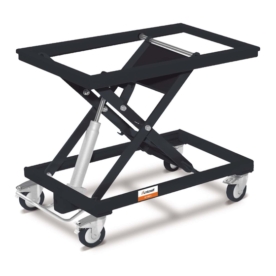
Lift table
Hide thumbs
1
Table Of Contents
2
3
4
5
6
7
8
9
10
11
12
13
14
15
16
17
18
19
20
21
22
23
24
25
26
page
of
26
Go
/
26
Contents
Table of Contents
Troubleshooting
Bookmarks
Table of Contents
Table of Contents
1 Introduction
Copyright
Customer Service
Limitation of Liability
2 Safety
Symbol Explanation
Obligations of the Operating Company
Requirements to Staff
Personal Protective Equipment
Safety Instructions
General Safety Regulations
Safety Regulations
Safety Instructions for Operating Personnel
Safety Labels on the Lift Table
3 Intended Use
Residual Risks
4 Technical Data
Table
Type Plate
5 Transport, Packaging, Storage
Transport
Packaging
Storage
6 Description of Device
Function
Accessories Work Plates (Optional)
7 Assembly
8 Commissioning
HT 300 M PSR: Disassembly and Installation of the Platform Swivel Device
9 Operation
Operating Conditions
Test Run
Using
Load or Unload Lifting Table
Lifting and Lowering the Load
Moving the Lift Table
10 Care, Maintenance and Repair
Care by Cleaning
Maintenance and Service/Repair
Servicing/Repair
11 Checking the Lift Table
12 Disposal, Recycling of Used Devices
Decommissioning
Disposal of Lubricants
13 Troubleshooting
14 Spare Parts
Ordering Spare Parts
Spare Parts Drawings
15 EU Declaration of Conformity
Advertisement
Quick Links
Download this manual
Operating instructions
Lift Table
HT 300 S, HT 300 M, HT 300 M PSR
HT 300 L, HT 300 L LAP, HT 600, HT 600 LAP
HT 300 S
HT 300 L
HT 300 M PSR
HT 600
Table of
Contents
Previous
Page
Next
Page
1
2
3
4
5
Advertisement
Table of Contents
Need help?
Do you have a question about the HT 300 S and is the answer not in the manual?
Ask a question
Questions and answers
Related Manuals for unicraft HT 300 S
Lifting Systems unicraft HT 600 LAP Operating Instructions Manual
Lift table (26 pages)
Lifting Systems unicraft HZ 751 Operating Instructions Manual
Level hoist (20 pages)
Lifting Systems unicraft HZ 1501 Operating Instructions Manual
Level hoist (20 pages)
Lifting Systems unicraft HZ 3001 Operating Instructions Manual
Level hoist (20 pages)
Lifting Systems unicraft MH 3 Operating Instructions Manual
(16 pages)
Lifting Systems unicraft WK Series Operating Instructions Manual
Workshop crane (26 pages)
Lifting Systems unicraft K 1001 Operating Instructions Manual
(18 pages)
Lifting Systems unicraft PK 1 Operating Instructions Manual
Mobile gantry crane (16 pages)
Lifting Systems unicraft SHB 3 Instruction Manual
Scissor lift (23 pages)
This manual is also suitable for:
Ht 300 m
Ht 300 m psr
Ht 300 l
Ht 300 l lap
Ht 600
Ht 600 lap
...
Show all
6100300
6100310
6100315
6100320
6100325
6100600
6100605
Table of Contents
Print
Rename the bookmark
Delete bookmark?
Delete from my manuals?
Login
Sign In
OR
Sign in with Facebook
Sign in with Google
Upload manual
Upload from disk
Upload from URL


Need help?
Do you have a question about the HT 300 S and is the answer not in the manual?
Questions and answers