Table of Contents
Advertisement
Quick Links
Advertisement
Table of Contents

Summary of Contents for unicraft SHB 3
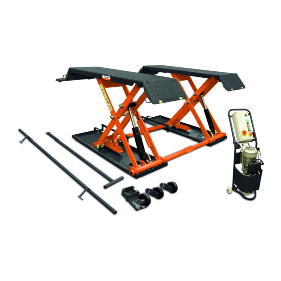
- Page 1 Instruction Manual Scissor lift SHB 3 SHB 3...
- Page 2 14.1 Ersatzteilbestellung ........16 its content are prohibited if not explicitly permitted. Con- 14.2 Ersatzteilzeichnungen ........17 traventions are liable to compensation. 15 Elektro-Schaltplan..........18 16 Hydraulik-Schaltplan...........19 Subject to technical modifications and error. 17 Druckluft-Schaltplan ...........19 18 EU-Konformitätserklärung .........20 SHB 3 | Version 1.02...
- Page 3 This combination of symbol and signal words indi- cates a potentially dangerous situation which may lead to death or severe injury if not avoided. SHB 3 | Version 1.02...
- Page 4 - The operator must have all safety devices checked tion of the user, the staff or for third par-ties. regularly for their good working order and their in- tegrity. SHB 3 | Version 1.02...
-
Page 5: Personal Protective Equipment
Please contact our cus- at first glance, the lift must be taken out of service until tomer service for the execution of all arising work. new safety markings have been applied. SHB 3 | Version 1.02... - Page 6 Safety 2.6 Warnings on the lifting platform Warnings are attached to the lifting platform (Fig. 2), which must be observed and followed. Fig. 2: Warnings on the lifting platform SHB 3 | Version 1.02...
-
Page 7: General Safety Regulations
NOTE! contact your dealer. The improper use (misuse) of the lift as well as the - Only use original UNICRAFT accessories and disregard of the safety regulations or the operating spare parts. instructions exclude any liability of the manufacturer... -
Page 8: Technical Data
- Lifting of vehicles that are not sufficiently secured on the lift. - Lifting of persons or other objects. Fig. 5: Type plate SHB 3 3.2 Residual risks Transport, Packaging, Storage - Risk of crushing when lowering the lift. -
Page 9: Requirements For The Installation Site
The following tools are required for assembly: - A new concrete floor must be dry for at least 28 days before the lift can be installed. - Electric drill - Wrench - Screwdriver - Hammer - Spirit level SHB 3 | Version 1.02... -
Page 10: Electrical Connection
- Lay the power cable so that it does not interfere with work and cannot be damaged. - Protect the power cord from heat, aggressive li- quids and sharp edges. Fig. 8: Driving equipment SHB 3 | Version 1.02... -
Page 11: Hydraulic Connection
Step 5: Fill the oil tank with hydraulic oil The distance between the oil level and the upper edge of the oil tank should be in the range of 10 to 30 mm. (Measurement with dipstick on the tank cap) SHB 3 | Version 1.02... -
Page 12: Operation
- Do not allow anyone to be under the lift while it is Fig. 16: Control panel being raised or lowered.. CAUTION! Risk of crushing! There is a risk of injury to upper and lower limbs when working improperly with the scissor lift. SHB 3 | Version 1.02... -
Page 13: Care, Maintenance And Repair
The contact details can be found in chapter 1.2 Customer service. All protective and safety devices must be reinstalled im- mediately after repair and maintenance work has been completed. SHB 3 | Version 1.02... -
Page 14: Lubrication Points
- Check all screws, bolts and nuts, retighten if neces- sary. - Check the hydraulic system for leaks and tighten the connections if they are leaking. - Check the lubrication and wear condition of the mo- ving parts. SHB 3 | Version 1.02... -
Page 15: Troubleshooting
3.Open the valve further. Safety interlock does not open 1.The air pressure regulating valve is 1. Set the air pressure to 5kg/cm2 closed or too low 2. Replace the solenoid valve. 2.The solenoid valve is damaged. SHB 3 | Version 1.02... -
Page 16: Spare Parts
The symbol on the product or its packaging indi- cates that this product should not be treated as normal The Compressed air cylinder for the Scissor lift SHB 3 household waste, but must be returned to a collection must be ordered. The Compressed air cylinder has the point for the recycling of electrical and electronic equip- number 22 in the spare parts drawing 1. -
Page 17: Spare Parts Drawings
In case of service, the following drawing shall help to identify the necessary spare parts. If necessary, send a copy of the parts drawing with the marked components to your authorised dealer. Spare parts drawing 1 Fig. 18: Spare parts drawing 1 SHB 3 | Version 1.02... -
Page 18: Electrical Circuit Diagram
Electrical circuit diagram Spare parts drawing 2 Fig. 19: Spare parts drawing 2 15 Electrical circuit diagram Fig. 20: Electrical circuit diagram SHB 3 | Version 1.02... -
Page 19: Hydraulic Circuit Diagram
Hydraulic circuit diagram 16 Hydraulic circuit diagram Fig. 21: Hydraulic circuit diagram 17 Compressed air circuit diagram Fig. 22: Compressed air circuit diagram SHB 3 | Version 1.02... -
Page 20: Ec Declaration Of Conformity
DIN EN 60204-1:2006+A1:2009 Safety of machinery - Electrical equipment of machines - Part 1: General requirements Kilian Stürmer, Stürmer Maschinen GmbH, Responsible for the documentation: Dr.-Robert-Pfleger-Str. 26, D-96103 Hallstadt Hallstadt, 27.05.2020 ______________________ Kilian Stürmer Manager SHB 3 | Version 1.02... - Page 21 Notes 19 Notes SHB 3 | Version 1.02...
- Page 22 www.unicraft.de...


Need help?
Do you have a question about the SHB 3 and is the answer not in the manual?
Questions and answers