Sign In
Upload
Download
Table of Contents
Contents
Add to my manuals
Delete from my manuals
Share
URL of this page:
HTML Link:
Bookmark this page
Add
Manual will be automatically added to "My Manuals"
Print this page
×
Bookmark added
×
Added to my manuals
Manuals
Brands
Miele Manuals
Hob
ProLine
Operating and installation instructions
Miele ProLine Operating And Installation Instructions
Hide thumbs
1
2
3
Table Of Contents
4
5
6
7
8
9
10
11
12
13
14
15
16
17
18
19
20
21
22
23
24
25
26
27
28
29
30
31
32
33
34
35
36
37
38
39
40
41
42
43
44
45
46
47
48
49
50
51
52
53
54
55
56
57
58
59
60
61
62
63
64
65
66
67
68
page
of
68
Go
/
68
Contents
Table of Contents
Bookmarks
Table of Contents
Table of Contents
Warning and Safety Instructions
Caring for the Environment
Guide to the Appliance
Wok
Indicators
Burner
Accessories Supplied
Before Using for the First Time
Cleaning the Proline Element for the First Time
Switching on the Proline Element for the First Time
Pans
Wok Ring
Tips on Saving Energy
Operation
Rapid Ignition System
Switching on
Adjusting the Flame
Switching off
In Operation / Residual Heat Indicators
Safety Features
Ignition Safety
Optional Accessories
Cleaning and Care
Stainless Steel Trough
Stainless Steel Frame/Control Panel
Rotary Controls
Pan Supports
Burner
Assembling the Burners
Problem Solving Guide
After Sales Service
Contact in the Event of a Fault
Data Plate
Warranty
Installation
Safety Instructions for Installation
Safety Distances
Installation Notes
Building-In Dimensions
Installing Several Proline Elements
Installation
Gas Connection
Burner Ratings
Electrical Connection
Converting to Another Gas Type
Jet Table
Changing the Jets
Checking the First Intake of Air
Changing the Small Jet
Functional Check
Product Data Sheets
Advertisement
Quick Links
Download this manual
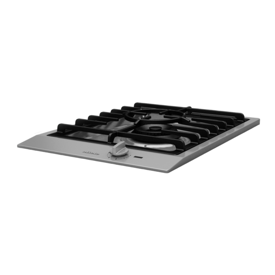
Operating and installation
instructions
ProLine Gas wok
To avoid the risk of accidents or damage to the appliance it is essen-
tial to read these instructions before it is installed and used for the
first time.
en-GB
M.-Nr. 11 138 530
Table of
Contents
Previous
Page
Next
Page
1
2
3
4
5
Advertisement
Table of Contents
Need help?
Do you have a question about the ProLine and is the answer not in the manual?
Ask a question
Questions and answers
Related Manuals for Miele ProLine
Hob Miele ProLine CS 1212-1 Operating And Installation Instructions
(60 pages)
Hob Miele ProLine CS 1212-1 Operating And Installation Instructions
(64 pages)
Hob Miele ProLine CS 1013-1 Operating And Installation Instructions
(52 pages)
Hob Miele Miele@home XKM 2000 KM Installation Instructions Manual
Fitting and installation instructions (32 pages)
Hob Miele KM 5600 Operating And Installation Instructions
(64 pages)
Hob Miele KM 362 Operating Instructions Manual
(28 pages)
Hob Miele KM 360 G Operating Instructions Manual
Gas (28 pages)
Hob Miele KM 5941 Operating And Installation Instructions
Ceramic hobs with induction (84 pages)
Hob Miele KM 460 Operating Instructions Manual
Ceramic (36 pages)
Hob Miele KM 460 Installation Instructions Manual
Ceramic (25 pages)
Hob Miele KM 6220 Operating Instructions Manual
Ceramic (72 pages)
Hob Miele KM 523 Operating And Installation Instructions
(36 pages)
Hob Miele KM 2034 Operating And Installation Manual
Gas (52 pages)
Hob Miele KM 6629 Operating And Installation Instruction
(84 pages)
Hob Miele KMDA 7476 FR Operating And Installation Instructions
(100 pages)
Hob Miele KMR 1124 LP Operating And Installation Instructions
30", 36", 48" rangetop (68 pages)
This manual is also suitable for:
Cs 1011-1
Cs 1021-1
Table of Contents
Print
Rename the bookmark
Delete bookmark?
Delete from my manuals?
Login
Sign In
OR
Sign in with Facebook
Sign in with Google
Upload manual
Upload from disk
Upload from URL


Need help?
Do you have a question about the ProLine and is the answer not in the manual?
Questions and answers