Miele ProLine CS 1212-1 Operating And Installation Instructions
Hide thumbs
Also See for ProLine CS 1212-1:
- Operating and installation instructions (64 pages) ,
- Operating and installation instructions (60 pages) ,
- Operating and installation instructions (56 pages)
Table of Contents

Related Manuals for Miele ProLine CS 1212-1


Summary of Contents for Miele ProLine CS 1212-1
- Page 1 Operating and installation instructions ProLine induction hob To avoid the risk of accidents or damage to the appliance it is essen- tial to read these instructions before it is installed and used for the first time. en-GB M.-Nr. 09 055 450...
-
Page 2: Table Of Contents
Contents Warning and Safety instructions..............Caring for the environment ................15 Guide to the appliance ..................16 Hob........................16 CS 1212-1, CS 1212-2................... 16 CS 1221-1 ...................... 17 CS 1222......................18 Controls and display ................... 19 Cooking zones..................... 20 Before using for the first time ................21 Cleaning the ProLine element for the first time ........... - Page 3 Contents Problem solving guide ..................37 Messages in the display..................37 General problems or technical faults..............39 Optional accessories ..................40 After sales service..................... 41 Contact in the event of a fault ................41 Data plate ......................41 Warranty ......................41 Installation......................
-
Page 4: Warning And Safety Instructions
Miele cannot be held liable for injury or damage caused by non- compliance with these instructions. Keep these instructions in a safe place and pass them on to any... - Page 5 Warning and Safety instructions Correct application This hob is intended for domestic use and use in other similar en- vironments. This hob is not intended for outdoor use. It is intended for domestic use only to cook food and keep it warm.
- Page 6 Warning and Safety instructions Safety with children Children under 8 years of age must be kept away from the hob unless they are constantly supervised. Children over 8 years of age may use the hob without supervision if its operation has been clearly explained to them and they are able to use it safely.
- Page 7 Unauthorised installation, maintenance and repairs can cause considerable danger for the user. Installation, maintenance and re- pairs must only be carried out by a Miele authorised technician. Damage to the hob can compromise your safety. Check the hob for visible signs of damage.
- Page 8 Miele authorised service technician. Otherwise the war- ranty is invalidated. Miele can only guarantee the safety of the appliance when genu- ine original Miele replacement parts are used. Faulty components must only be replaced by Miele spare parts.
- Page 9 Switch it off immediately. Disconnect the hob from the mains electricity sup- ply. Contact Miele Service. If the hob is installed behind a cabinet door, do not close the door while the hob is in use.
- Page 10 Warning and Safety instructions Correct use The hob gets hot when in use and remains hot for a while after be- ing switched off. There is a danger of burning until the residual heat indicators go out. Oil and fat can overheat and catch fire. Do not leave the hob unat- tended when cooking with oil and fat.
- Page 11 Warning and Safety instructions You could burn yourself on the hot hob. Protect your hands with heat-resistant pot holders or gloves when handling hot pots and pans. Do not let them get wet or damp, as this causes heat to trans- fer through the material more quickly with the risk of scalding or burning yourself.
- Page 12 Warning and Safety instructions Because induction heating works so quickly, the base of the pan could, under certain circumstances, heat up to the temperature at which oil or fat self-ignites within a very short time. Never leave the hob unattended during use! ...
- Page 13 Warning and Safety instructions Where several ProLine elements are installed side by side: Hot objects can damage the seal on the spacer bars. Do not place hot pans near or on the spacer bar.
- Page 14 (see relev- ant section). Miele will guarantee to supply functional spare parts for a min- imum of 10 years and up to 15 years following the discontinuation of your ProLine element.
-
Page 15: Caring For The Environment
Miele, free of charge. By law, you are solely responsible for deleting any personal data from the old appliance prior to disposal. You are legally obliged... -
Page 16: Guide To The Appliance
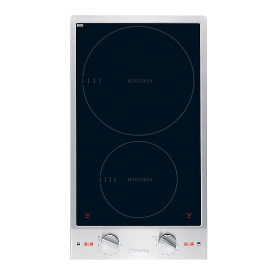
Guide to the appliance CS 1212-1, CS 1212-2 a Cooking zone with TwinBooster b Cooking zone with Booster function c Cooking zone display d Symbols for allocation of operating controls e Indicators f Rotary controls... - Page 17 Guide to the appliance CS 1221-1 a Cooking zone with TwinBooster b Cooking zone display c Indicators d Rotary control...
- Page 18 Guide to the appliance CS 1222 a Extended zone with TwinBooster b Cooking zone with Booster function c Cooking zone display d Symbols for allocation of operating controls e Indicators f Rotary controls...
-
Page 19: Controls And Display
Guide to the appliance Controls and display Rotary control symbols Symbol Description Cooking zone off Keeping warm setting 1–9 Power levels B I Booster function with 1 level B I/II TwinBooster with 2 levels Cooking zone display Symbol Description Missing or unsuitable crockery ... -
Page 20: Cooking Zones
Guide to the appliance Cooking zones CS 1212-1, CS 1212-2 Cooking zone Ø in cm Rating in watts for 230 V 16–23 Normal 2300 TwinBooster, level 1 3000 TwinBooster, level 2 3700 10–16 Normal 1400 Booster 2200 Total 3700 CS 1221-1 Ø in cm Rating in watts for 230 V 18–28 Normal 2600... -
Page 21: Before Using For The First Time
Before using for the first time Please stick the extra data plate for Switching on the ProLine ele- the appliance supplied with this doc- ment for the first time umentation in the space provided in the “After sales service” section of When the hob is first connected, and this booklet. -
Page 22: How It Works
How it works An induction coil is located under each Noises induction cooking zone. The coil cre- When using an induction hob, the fol- ates a magnetic field that reacts directly lowing noises can occur in the pan, de- with the base of the pan and heats it pending on what it is made of and how up. -
Page 23: Power Management
How it works If a cooking zone gives power to an- Power management other zone, this can have the following The hob has a maximum total permitted effects: power consumption which cannot be - The power level is reduced. exceeded for safety reasons. - Auto heat-up is deactivated. -
Page 24: Pans
Pans Suitable pans No cookware/unsuitable cook- ware display - stainless steel pans with a magnetic base The symbol flashes in the cooking zone display if: - enamelled steel pans - The cooking zone has been switched - cast iron pans on without cookware in place, or if Please be aware that the properties of the cookware is unsuitable (non-... - Page 25 Pans - Please note that the cookware dia- Tips meter quoted by manufacturers often - To make optimum use of the cooking refers to the maximum diameter or zones, choose cookware with a suit- diameter of the top rim. The diameter able base diameter (see “Overview –...
-
Page 26: Tips On Saving Energy
Tips on saving energy - Use a lid whenever possible to min- imise heat loss. - Select a smaller pan when cooking small quantities. A smaller pan uses less energy than a larger pan with very little in it. - Cook with as little water as possible. - Once food has come to the boil or the oil in the pan is hot enough for frying, reduce the heat to a lower set-... -
Page 27: Setting Ranges
Setting ranges Setting range Keeping warm Melting butter 1–2 Dissolving gelatine Melting chocolate Making milk puddings Warming small quantities of liquid Cooking rice Defrosting frozen vegetables Cooking pulses Warming liquid and semi-solid foods Making omelettes or fried eggs Steaming fruit Cooking pasta Steaming vegetables, fish Defrosting and reheating frozen food... -
Page 28: Operation
Operation Residual heat indicator Risk of fire with overheated food. Unattended food can overheat and If the cooking zone is still hot, the resid- catch alight. ual heat indicator will light up after it has been switched off. Do not leave the hob unattended whilst it is being used. -
Page 29: Auto Heat-Up
Operation Auto heat-up Continued cook- Heat-up time ing level [min:sec] When Auto heat-up has been activated, the cooking zone switches on automat- Approx. 00:15 ically at the highest setting and then Approx. 00:15 switches to the continued cooking set- ting which you have previously selec- Approx. -
Page 30: Booster Function
Operation Activating the Booster Booster function Turn the rotary control gently clock- The cooking zones are equipped with a wise past 9 to B I and back to 9. Booster function (see “Guide to the ap- pliance – Hob”). will appear in the cooking zone display and B will appear in the indicator. -
Page 31: Keeping Warm
Operation Setting the keeping warm setting Keeping warm Turn the rotary control clockwise to This function is for keeping food warm position . which has just been cooked and is still hot. It is not for reheating food that has gone cold. -
Page 32: Safety Features
Safety features System lock Safety switch-off The safety switch-off mechanism is The system lock can only be activated triggered automatically if one of the if all the cooking zones are switched cooking zones is heated for an unusu- off. ally long period of time. This period of Your hob is equipped with a system time depends on the power level selec- lock to prevent the cooking zones being... -
Page 33: Overheating Protection
Safety features The overheating protection may be ac- Overheating protection tivated under the following circum- All the induction coils and heat sinks for stances: the electronic module are fitted with an - The cookware being heated is empty. overheating protection mechanism. Be- fore the induction coils or heat sinks get - Fat or oil is being heated on a high too hot, the overheating protection... -
Page 34: Cleaning And Care
Cleaning and care Allow the ProLine element to cool Risk of burning due to hot cook- down before cleaning. ing zones. The cooking zones will be hot after Clean the ProLine element and ac- use. cessories after each use. Switch the hob off. -
Page 35: Cleaning The Stainless Steel Frame/Control Panel
Cleaning and care Clean the frame and the control panel Cleaning the stainless steel with a solution of warm water and a frame/control panel little washing-up liquid applied with a soft sponge. Soften any stubborn Risk of damage by pointed ob- soiling beforehand. -
Page 36: Cleaning The Glass Ceramic Surface
Then carefully scrape off these Then clean the glass ceramic surface residues immediately whilst they are with the Miele ceramic and stainless still hot, using a scraper suitable for steel cleaner (see “Optional ac- use on glass. -
Page 37: Problem Solving Guide
Problem solving guide Many malfunctions and faults that can occur in daily operation can be easily remedied. Time and money will be saved because a service call will not be needed. The following guide may help you to find the reason for a malfunction or a fault, and to correct it. - Page 38 Problem solving guide Problem Cause and remedy flashes alternately The power level was reduced because the Booster with the power level in function was switched on on the linked cooking the cooking zone dis- zone (see “How it works – Power management”). play.
-
Page 39: General Problems Or Technical Faults
There is no power to the hob. not heat up. Check whether the fuse has tripped. Contact a qualified electrician or the Miele Customer Service Department (for the minimum fuse rating, see data plate). There may be a technical fault. -
Page 40: Optional Accessories
These products can be ordered through the Miele Webshop. Microfibre cloth They can also be ordered from Miele For removing finger marks and light (see end of this booklet for contact de- soiling. tails) or from your Miele dealer. -
Page 41: After Sales Service
You can book a Miele Customer Service Department call-out online at www.miele.com/service. Contact information for the Miele Customer Service Department can be found at the end of this document. Please quote the model identifier and serial number of your appliance (Fabr./SN/ Nr.) when contacting the Miele Customer Service Department. -
Page 42: Installation
*INSTALLATION* Installation Safety instructions for installation Risk of damage from incorrect connection. Incorrect installation can cause damage to the ProLine element. The ProLine element must only be installed by a qualified person. Risk of electric shock from mains voltage. Incorrect connection to the mains supply may result in an electric shock. -
Page 43: Safety Distances
*INSTALLATION* Installation Safety distances Safety distance above the ProLine element The safety distance specified by the manufacturer of the cooker hood must be maintained between the ProLine ele- ment and the cooker hood above it. If the cooker hood manufacturer’s in- structions are not available or if com- bustible objects are installed above the ProLine element (e.g. - Page 44 *INSTALLATION* Installation Safety distances to the sides and back of the appliance Ideally the ProLine element should be installed with plenty of space on either side. The minimum safety distance shown below must be maintained between the back of the ProLine element and a tall unit or wall.
- Page 45 *INSTALLATION* Installation Minimum safety distance underneath Intermediate shelf the ProLine element It is not necessary to fit an interim shelf To ensure proper ventilation of the Pro- underneath the ProLine element but Line element, a minimum safety dis- one may be fitted if you wish. tance is required between the element and an oven, interim shelf or drawer.
- Page 46 *INSTALLATION* Installation Safety distance to niche cladding If niche cladding is installed, a minimum safety distance must be maintained between the worktop cut-out and the cladding, since high temperatures can alter or damage these materials. If the niche cladding is made from a combustible material (e.g. wood), a minimum safety distance ...
-
Page 47: Installation Notes
*INSTALLATION* Installation Tiled worktop Installation notes Sealing between the ProLine Element and the worktop Grout lines and the hatched area un- derneath the ProLine element frame must be smooth and even. If they are not, the ProLine element will not sit flush with the worktop and the sealing ... -
Page 48: Building-In Dimensions
*INSTALLATION* Installation Building-in dimensions All dimensions are given in mm. CS 1212-1, CS 1212-2 a Spring clamps b Front c Appliance height d Casing depth for mains connection box with mains connection cable Mains connection cable L = 1440 mm... - Page 49 *INSTALLATION* Installation CS 1221-1, CS 1222 a Spring clamps b Front c Appliance height d Casing depth for mains connection box with mains connection cable Mains connection cable L = 1440 mm...
-
Page 50: Worktop Cut-Out For Several Proline Elements
*INSTALLATION* Installation Worktop cut-out for several ProLine elements Example: 3 ProLine elements a Spring clamps b Spacer bars c Gap between spacer bars and worktop d Cover e ProLine element width minus 8 mm f ProLine element width g ProLine element width minus 8 mm h Worktop cut-out... - Page 51 *INSTALLATION* Installation Calculating the worktop cut-out The frames of the ProLine elements overlap the worktop at the outside right and left by 8 mm on each side. Add up the widths of the ProLine elements and subtract 16 mm from this figure. Example: 288 mm + 288 mm + 380 mm = 956 mm - 16 mm = 940 mm The ProLine elements are 288 mm, 380 mm or 576 mm wide depending on the...
-
Page 52: Installation
*INSTALLATION* Installation Securing the spring clamps and Installation spacer bars – wooden worktops Preparing the worktop Make the worktop cut-out as shown in “Installation dimensions” or as cal- culated (see “Installation – Installing several ProLine elements”). Remem- ber to maintain the minimum safety distances (see “Installation –... - Page 53 *INSTALLATION* Installation Securing the spring clamps and spacer bars – granite and marble worktops You will need heavy-duty double-sided tape (not supplied) to secure the spring clamps or spacer bars. Apply silicone to the side and lower edges of the spring clamps or spacer bars .
- Page 54 *INSTALLATION* Installation Installation with a downdraft ex- Installing several ProLine elements tractor Push the built-in ProLine element to Please refer to the “Downdraft extractor the side until the holes in the spacer with ProLine elements” operating and bar can be seen. installation instructions for details about installing the downdraft extractor and the ProLine elements.
- Page 55 *INSTALLATION* Installation Connecting the ProLine element Removing a ProLine element Connect the ProLine element(s) to the If the ProLine element cannot be ac- mains electricity supply. cessed from below, you will need a special tool to remove it. Check that each ProLine element is working.
-
Page 56: Electrical Connection
Miele product must also be maintained The electrical installation must comply in isolated operation or in operation that with BS 7671 requirements. is not synchronised with the mains... -
Page 57: Product Data Sheets
The following data sheets apply to the models described in this operating instruc- tion manual. Information for domestic electric hobs In acc. with regulation (EU) No. 66/2014 MIELE Model name/identifier CS 1212-1, CS 1212-2 Number of cooking zones and/or areas For circular cooking zones: diameter of useful sur- 1. - Page 58 Product data sheets Information for domestic electric hobs In acc. with regulation (EU) No. 66/2014 MIELE Model name/identifier CS 1222 Number of cooking zones and/or areas For circular cooking zones: diameter of useful sur- 1. = Ø 100-160 mm face area/cooking zone 2.
- Page 59 United Kingdom Miele Co. Ltd., Fairacres, Marcham Road, Abingdon, Oxon, OX14 1TW Tel: 0330 160 6600, Internet: www.miele.co.uk/service, E-mail: info@miele.co.uk Australia Ireland Singapore Miele Australia Pty. Ltd. Miele Ireland Ltd. Miele Pte. Ltd. ACN 005 635 398 2024 Bianconi Avenue...
- Page 60 CS 1212-1, CS 1212-2, CS 1221-1, CS 1222 en-GB M.-Nr. 09 055 450 / 12...
Need help?
Do you have a question about the ProLine CS 1212-1 and is the answer not in the manual?
Questions and answers