Miele KM 6629 Operating And Installation Instruction
Hide thumbs
Also See for KM 6629:
- Operating and installation instruction manual (84 pages) ,
- Operating and installation instructions (76 pages)
Table of Contents

Related Manuals for Miele KM 6629


Summary of Contents for Miele KM 6629
- Page 1 Operating and installation instructions Ceramic hobs with induction To avoid the risk of accidents or damage to the appliance it is essential to read these instructions before it is installed and used for the first time. en-GB M.-Nr. 10 378 320...
-
Page 2: Table Of Contents
Caring for the environment ................ 14 Guide to the appliance .................. 15 Hob........................15 KM 6629 / KM 6639 / KM 6839................ 15 KM 6669 / KM 6679 / KM 6879................ 16 KM 6699 ...................... 17 Controls / Indicators....................18 Cooking zones....................... - Page 3 Programming ....................... 46 Cleaning and care .................... 51 Problem solving guide .................. 53 Optional accessories .................. 56 Miele@home / Con@ctivity ................ 57 To access programming mode................57 Safety instructions for installation.............. 58 Safety distances .................... 59 Hob with frame or bevelled edge............... 63 Installation notes ....................
- Page 4 Contents Product data sheets ................... 77 Conformity declaration .................. 81...
-
Page 5: Warning And Safety Instructions
They contain important notes on in- stallation, safety, use and maintenance. Miele cannot be held liable for damage caused by non-compliance with these instructions. Keep these instructions in a safe place and ensure that new users... - Page 6 Warning and Safety instructions Correct application This hob is intended for domestic use and use in other similar en- vironments. This hob is not intended for outdoor use. It is intended for domestic use only to cook food and keep it warm.
- Page 7 Warning and Safety instructions Safety with children Children under 8 years of age must be kept away from the hob unless they are constantly supervised. Children 8 years and older may only use the hob unsupervised if they have been shown how to use it in a safe way and can recognise and understand the consequences of incorrect operation.
- Page 8 Unauthorised installation, maintenance and repairs can cause considerable danger for the user. Installation, maintenance and re- pairs must only be carried out by a Miele authorised technician. Do not use a damaged appliance. It could be dangerous. Check the hob for visible signs of damage.
- Page 9 Warning and Safety instructions Miele can only guarantee the safety of the appliance when genu- ine original Miele replacement parts are used. Faulty components must only be replaced by Miele spare parts. The hob is not intended for use with an external timer switch or a remote control system.
- Page 10 Warning and Safety instructions Correct use The hob gets hot when in use and remains hot for a while after be- ing switched off. There is a danger of burning until the residual heat indicators go out. Oil and fat can overheat and catch fire. Do not leave the hob unat- tended when cooking with oil and fat.
- Page 11 Warning and Safety instructions You could burn yourself on the hot hob. Protect your hands with heat-resistant pot holders or gloves when handling hot pots and pans. Do not let them get wet or damp, as this causes heat to trans- fer through the material more quickly with the risk of scalding or burning yourself.
- Page 12 Warning and Safety instructions Induction heating works extremely quickly and so the base of the pan could heat up to the temperature at which oil or fat self-ignites within a very short time. Do not leave the hob unattended whilst it is being used.
-
Page 13: Cleaning And Care
Warning and Safety instructions Cleaning and care Do not use a steam cleaning appliance to clean this hob. The steam could reach electrical components and cause a short cir- cuit. If the hob is built in over a pyrolitic oven, the hob should not be used whilst the pyrolitic process is being carried out, as this could trigger the overheating protection mechanism on the hob (see relev- ant section). -
Page 14: Caring For The Environment
Caring for the environment Disposal of the packing mater- Disposal of your old appliance Electrical and electronic appliances of- ten contain valuable materials. They The packaging is designed to protect also contain materials which, if handled the appliance from damage during or disposed of incorrectly, could be po- transportation. -
Page 15: Guide To The Appliance
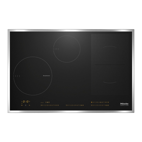
Guide to the appliance KM 6629 / KM 6639 / KM 6839 a Cooking zone with TempControl* and TwinBooster b Cooking zone with TwinBooster c PowerFlex cooking zone with TwinBooster d PowerFlex cooking zone with TwinBooster cd can be combined to form a PowerFlex cooking area e Controls / Indicators * On some hobs the ceramic surface in the middle of the cooking zone with Temp-... - Page 16 Guide to the appliance KM 6669 / KM 6679 / KM 6879 a Cooking zone with TwinBooster b Cooking zone with TempControl* and TwinBooster c Cooking zone with TwinBooster d PowerFlex cooking zone with TwinBooster e PowerFlex cooking zone with TwinBooster de can be combined to form a PowerFlex cooking area f Controls / Indicators * On some hobs the ceramic surface in the middle of the cooking zone with Temp-...
- Page 17 Guide to the appliance KM 6699 a Cooking zone with TempControl* and TwinBooster b PowerFlex cooking zone with TwinBooster c PowerFlex cooking zone with TwinBooster bc can be combined to form a PowerFlex cooking area d Cooking zone with TwinBooster e Controls / Indicators * On some hobs the ceramic surface in the middle of the cooking zone with Temp- Control is transparent and the temperature sensor is visible.
-
Page 18: Controls / Indicators
Guide to the appliance Controls / Indicators Sensors For switching the hob on and off 1, 2 , 3 ..9, B Numerical keybank - For setting the power level: 1–9 = Power level B = Booster - For setting a minute minder - For setting a switch-off time ... - Page 19 Guide to the appliance Timer a Minute minder sensor b Cooking zone indicator c Timer display : to Duration : System lock/safety lock activated altern- Demonstration mode activated ating with d Sensor for selecting the cooking zone automatic switch-off...
-
Page 20: Cooking Zones
Guide to the appliance Cooking zones Cooking zone KM 6629 / KM 6639 / KM 6839 Ø in cm* Rating in watts for 230 V** 16–23 Normal 2300 TwinBooster, level 1 3000 TwinBooster, level 2 3650 10–16 Normal 1400... - Page 21 Guide to the appliance Cooking zone KM 6669 / KM 6679 / KM 6879 Ø in cm* Rating in watts for 230 V** 10–16 Normal 1400 TwinBooster, level 1 1750 TwinBooster, level 2 2200 16–23 Normal 2300 TwinBooster, level 1 3000 TwinBooster, level 2 3650...
- Page 22 Guide to the appliance Cooking zone KM 6699 Ø in cm* Rating in watts for 230 V** 16–23 Normal 2300 TwinBooster, level 1 3000 TwinBooster, level 2 3650 15–23 Normal 2100 TwinBooster, level 1 3000 TwinBooster, level 2 3650 ...
-
Page 23: Using For The First Time
Using for the first time Please stick the extra data plate for Switching on the hob for the the appliance supplied with this doc- first time umentation in the space provided in The metal components have a protect- the "After sales service, data plate, ive coating which may give off a slight guarantee"... -
Page 24: Induction
Induction The induction principle When the appliance is switched on either deliberately or by mistake, An induction coil is located under each or when there is residual heat cooking zone. When a cooking zone is present, there is the risk of any metal switched on, this coil creates a mag- items placed on the hob (e.g. -
Page 25: Noises
Induction Noises When using an induction cooking zone, the following noises can occur in the pan, depending on what it is made of and how it has been constructed. On the higher power settings, it might buzz. This will decrease or cease alto- gether when the power setting is re- duced. -
Page 26: Pans
Induction – To make optimum use of the cooking Pans zones, choose pans with a suitable The following pan types are suitable: base diameter (see "Cooking zones"). If the pan is too small it will not be re- – stainless steel with a magnetic base, cognised and the set power level will –... -
Page 27: Tips On Saving Energy
Tips on saving energy – Use a lid whenever possible to min- imise heat loss. – Select a smaller pan when cooking small quantities. A smaller pan uses less energy than a larger pan with very little in it. – Cook with as little water as possible. –... -
Page 28: Setting Range
Setting range The hob is programmed with 9 power levels at the factory. If you wish to fine-tune a setting, you can extend the power setting range to 17 power levels (see "Pro- gramming"). Setting range Default set- Extended set- ting tings (9 power... -
Page 29: Operation
Operation How the hob is operated Malfunction due to dirty and/or covered sensors This glass ceramic hob is equipped with If the sensors are dirty or covered electronic sensor controls which react this could cause them to fail to react, to finger contact. -
Page 30: Switching On The Hob
Operation Switching off Fire hazard. Do not leave the hob unattended To switch a cooking zone off, touch the sensor on the appropriate key- whilst it is being used. Please note that the heating up time bank. on induction hobs is very much ... -
Page 31: Tempcontrol
Operation Notes on use TempControl – Make sure that the ceramic surface is TempControl monitors and controls the kept clean, particularly in the area of temperature during frying: the sensor in the middle of the cook- – the fat cannot overheat, ing zone. - Page 32 Operation Activating TempControl Frying level Place a pan on the cooking zone and Potato pancakes add frying fat/oil if necessary. Fried potatoes made from raw potatoes Touch the sensor for the frying level Meat loaf you want to use ( ,, ). Steaks The sensor for the frying level selected will start to pulsate.
-
Page 33: Setting The Power Level - Extended Setting Range
Operation Setting the power level - exten- PowerFlex cooking area ded setting range The PowerFlex cooking zones combine automatically to form a PowerFlex Touch the area between the sensors. cooking area when you place a suffi- The sensors in front of and after the in- ciently large pot or pan on them (see terim level will light up brighter than the "Guide to the appliance - Hob"). -
Page 34: Auto Heat-Up
Operation Auto heat-up Continued cook- Heat-up time ing setting [min : sec] When Auto heat-up has been activated, the cooking zone switches on automat- approx. 0 : 15 ically at the highest power setting and approx. 0 : 15 then switches to the continued cooking setting. -
Page 35: Booster
Operation Cooking zones are networked in pairs Booster to supply the power for the booster The cooking zones are equipped with a function. When the booster function is TwinBooster. You can use the booster selected, a proportion of energy is function for a maximum of two cooking taken away from the linked cooking zones at the same time. - Page 36 Operation To switch on the TwinBooster, level 1 To switch off the TwinBooster Place a pan on the cooking zone you Touch the B sensor. want to use. – once (Booster) Select a power level if necessary. – repeatedly until the indicator lights go ...
-
Page 37: Keeping Warm / Warming Up
Operation To switch the Keeping warm setting Keeping warm / warming up on/off The Keeping warm setting is for Touch the or sensor. keeping food that has just been cooked warm, i.e. food that is still hot. It is not for reheating food that has gone cold. -
Page 38: Timer
Timer The hob has to be switched on if you The functions can be used at the same wish to use the timer. time. The shortest time is always dis- You can set a duration between played and the sensor (minute 1 minute (:) and 9 hours 59 minutes minder) or the indicator light for the cooking zone (automatic switch-off) -
Page 39: Switching A Cooking Zone Off Automatically
Timer If you want to set another cooking Switching a cooking zone off zone to switch off automatically, fol- automatically low the same steps as described You can set a time at the end of which a above. cooking zone will switch off automatic- ally. -
Page 40: Additional Functions
Additional functions Stop&Go Recall When Stop&Go is activated, the power If the hob is accidentally switched off of all cooking zones in use is reduced to during use, you can use this function to power level 1. restore all the settings. The hob must The cooking zone power levels and the be switched on again within timer settings cannot be altered and the... -
Page 41: Wipe Protection
Additional functions Wipe protection Displaying the hob data You can display the model number and You can lock the hob sensors for 20 software version of your hob. To do this seconds in order to remove soiling, for there must not be any pots or pans on example. -
Page 42: Safety Features
Safety features Activating the system lock System lock / Safety lock Touch the sensor for 6 seconds. The system lock and safety lock are deactivated if there is an interruption The time will count down in the timer to the power supply. display. -
Page 43: Safety Switch-Off
Safety features Safety switch-off Power level* Maximum operating time [h:min] Safety switch-off with an overlong Safety setting cooking time The safety switch-off mechanism is 10:00 8:00 5:00 triggered automatically if one of the cooking zones is heated for an unusu- 10:00 7:00 4:00... - Page 44 Safety features Safety switch-off if the sensors are covered Your hob will switch off automatically if one or several sensors remain covered for more than about 10 seconds, for ex- ample by finger contact, food boiling over or an object. will flash briefly above the ...
-
Page 45: Overheating Protection
If, despite removing the cause, the – The set power level will be reduced. overheating protection mechanism trig- gers again, contact Miele. – The cooking zone switches off auto- matically. flashes in the timer dis- play alternating with . -
Page 46: Programming
Programming You can programme certain settings on To access programming mode the hob to suit your personal needs. With the hob switched off, touch Several settings can be changed in suc- the and sensors at the same cession. time until the ... - Page 47 C:01 System lock activated automatic- ally P:09 Maximum operating time C:00 Safety setting 0 C:01 Safety setting 1 C:02 Safety setting 2 P:10 Miele@home/Con@ctivity C:00 Not available C:01 Signed off C:02 Signed on P:12 Sensor reaction speed C:00 Slow C:01...
- Page 48 Programming Settings Programme Code P:15 Permanent pan recognition C:00 Not active C:01 Active P:16 Maximum pan temperature C:00 160 °C with manual frying and cook- C:01 170 °C C:02 180 °C C:03 190 °C C:04 200 °C C:05 210 °C C:06 220 °C C:07 230 °C C:08 240 °C C:09 250 °C P:17...
- Page 49 Programming Settings Programme Code Frying level temperature P:20 C:00 180 °C C:01 185 °C C:02 190 °C C:03 195 °C C:04 200 °C C:05 205 °C C:06 210 °C C:07 215 °C C:08 220 ° Frying level temperature P:21 C:00 200 °C C:01 205 °C C:02 210 °C C:03 215 °C C:04 220 °C C:05...
- Page 50 Programming Settings Programme Code P:25 Keeping warm plus tem- C:00 50 °C perature C:01 55 °C C:02 60 °C C:03 65 °C C:04 70 °C C:05 75 °C C:06 80 °C C:07 85 °C C:08 90 °C Unlisted programmes are not assigned. The factory setting is shown in bold. After the hob has been switched on ...
-
Page 51: Cleaning And Care
Cleaning and care Clean the entire hob after each use. Al- Danger of burning. low it to cool down before cleaning. Dry The cooking zones must be switched the hob after using water to clean it. off. The hob must have cooled down. This helps prevents limescale deposits. - Page 52 Wipe all coarse soiling off using a damp cloth. Stubborn soiling may need to be removed with a shielded scraper blade. Then clean the hob with Miele ceramic and stainless steel hob cleaner (see "Optional accessories") or a suitable proprietary ceramic hob cleaning agent applied with kitchen paper or a clean cloth.
-
Page 53: Problem Solving Guide
Do not open the casing of the appliance. Repairs and other work by unqualified persons could be dangerous and Miele cannot be held liable for unauthorised work. Problem... - Page 54 Problem solving guide Problem Cause and remedy After the hob has been The system lock or safety lock is activated. switched on or a sensor Deactivate the system lock or safety lock (see has been touched "System lock / Safety lock"). appears in the timer display for a few seconds.
- Page 55 The hob is incorrectly connected. alternating with flashes in the Contact Miele. The hob must be connected to the timer display. mains according to the wiring diagram. 1 and a number, e.g. 1-0 Cooking zone fault flashes alternately with ...
-
Page 56: Optional Accessories
Ceramic and stainless steel hob and conditioning products for your cleaner 250 ml Miele appliances. These can be ordered online or from Miele (see end of this booklet for con- Removes heavy soiling, limescale de- tact details). posits and aluminium residues Pans... -
Page 57: Miele@Home / Con@Ctivity
If you want to sign the hob off from – To sign the hob on to Con@ctivity, Miele@home, first carry out the sign- you must first sign the cooker hood ing off procedure on the master appli- ance. -
Page 58: Safety Instructions For Installation
Safety instructions for installation The appliance must only be installed and connected to the electricity supply by a suitably qualified and competent person in strict accordance with current national and local safety regulations. Fit the wall units and cooker hood before fitting the hob to avoid damaging the hob. -
Page 59: Safety Distances
Safety distances Safety distance above the hob A minimum safety distance must be maintained between the appliance and the cooker hood above it. See the cooker hood manufacturer's operating and installation instructions for details. If the manufacturer's instructions are not available for the cooker hood or if any flammable objects (e.g. - Page 60 Safety distances Safety distances to the sides and back of the hob Ideally the hob should be installed with plenty of space on either side. There may be a wall at the rear or a tall unit or wall on one side (right or left) (see illus- trations).
- Page 61 Safety distances Minimum safety distances un- Interim shelf derneath the hob It is not necessary to fit an interim shelf underneath the hob but one may be fit- To ensure sufficient ventilation to the ted if you wish. hob, a certain gap must be left between the underside of the hob and any oven, Leave a gap of 10 mm at the back of interim shelf or drawer.
- Page 62 Safety distances Safety distance when installing the appliance near a wall with additional niche cladding A minimum safety distance must be maintained between the worktop cut-out and any niche cladding to protect it from heat damage. If the niche cladding is made from a combustible material (e.g. wood) a minimum safety distance ...
-
Page 63: Hob With Frame Or Bevelled Edge
Hob with frame or bevelled edge Tiled worktop Installation notes Seal between the hob and the work- Grout lines and the hatched area un- derneath the hob frame must be smooth and even. If they are not the hob will not sit flush with the worktop and the sealing strip underneath the Do not use sealant between the hob hob will not provide a good seal... -
Page 64: Building-In Dimensions
Hob with frame or bevelled edge Building-in dimensions KM 6629 a Front b Casing depth c Mains connection box The mains connection cable (1440 mm long) is supplied separately with the hob. - Page 65 Hob with frame or bevelled edge KM 6669 a Front b Casing depth c Mains connection box The mains connection cable (1440 mm long) is supplied separately with the hob.
- Page 66 Hob with frame or bevelled edge KM 6699 a Front b Casing depth c Mains connection box The mains connection cable (1440 mm long) is supplied separately with the hob.
-
Page 67: Installation
Hob with frame or bevelled edge Installing the hob Installation Feed the mains connection cable Preparing the worktop down through the cut-out. Make the worktop cut-out as shown Place the hob centrally in the cut-out. in the building-in diagram. Observe When doing this, make sure that the the safety distances (see "Safety dis- seal under the hob sits flush with the... -
Page 68: Flush-Fitted Hobs
Flush-fitted hobs The hob can be installed Installation notes – in a suitable cut-out in a natural stone Flush fit hobs are only suitable for in- worktop. stallation in natural stone (granite, marble), tiled or solid wood worktops. – in a suitable cut-out in a tiled or solid Certain models are suitable for build- wood worktop or a glass worktop ing into glass worktops - please see... -
Page 69: Building-In Dimensions
Flush-fitted hobs Building-in dimensions KM 6639 / KM 6839 a Front b Appliance height c Mains connection box d Stepped cut-out The mains connection cable (1440 mm long) is supplied separately with the hob. Please observe the detailed diagrams for cut-out dimensions in natural stone worktops. - Page 70 Flush-fitted hobs KM 6679 / KM 6879 a Front b Appliance height c Mains connection box d Stepped cut-out The mains connection cable (1440 mm long) is supplied separately with the hob. Please observe the detailed diagrams for cut-out dimensions in natural stone worktops.
-
Page 71: Installation
Flush-fitted hobs KM 6679 / KM 6879 Installation Natural stone worktops d Stepped cut-out a Worktop Solid wood, tiled and glass worktops b Hob c Gap As the ceramic glass and the worktop cut-out have a certain dimensional tol- erance, the size of the gap can vary (min. - Page 72 Flush-fitted hobs Preparing the worktop Make the worktop cut-out as shown in "Building-in dimensions". Observe the safety distances (see "Safety dis- tances"). Solid wood, tiled and glass worktops: Fix the wooden frame 7 mm below the top edge of the worktop (see dia- gram).
-
Page 73: Electrical Connection
Electrical connection Connection Danger of injury. Miele cannot be held liable for unau- AC 230 V, 50 Hz thorised installation, maintenance The connection data is quoted on the and repair work as this can be dan- dataplate. It must match the household gerous to users. - Page 74 The earth lead must be connected to the point marked . If the mains cable needs to be replaced it must be replaced with a special con- nection cable, type H 05 VV-F (PVC-in- sulated), available from Miele. The connection data is quoted on the data plate.
-
Page 75: Wiring Diagram
Electrical connection Wiring diagram a b c d e 200-240 V~ 200-240 V~ 200-240 V~ (L3) 200-240 V~ 200-240 V~ b c d (L2) 200-240 V~... -
Page 76: After Sales Service, Data Plate, Guarantee
N.B. A call-out charge will be applied to service visits where the problem could have been resolved as described in these instructions. When contacting your Dealer or Miele, please quote the model and serial number of your appliance. Data plate Space in which to stick the extra data plate supplied with the appliance. -
Page 77: Product Data Sheets
Information for domestic electric hobs In acc. with regulation (EU) No. 66/2014 MIELE Model name / identifier KM 6629 Number of cooking zones and/or areas For circular cooking zones: diameter of useful sur- 1. = Ø 160-230 mm face area/cooking zone 2. - Page 78 Product data sheets Information for domestic electric hobs In acc. with regulation (EU) No. 66/2014 MIELE Model name / identifier KM 6669 Number of cooking zones and/or areas For circular cooking zones: diameter of useful sur- 1. = Ø 100-160 mm face area/cooking zone 2.
- Page 79 Product data sheets Information for domestic electric hobs In acc. with regulation (EU) No. 66/2014 MIELE Model name / identifier KM 6699 Number of cooking zones and/or areas For circular cooking zones: diameter of useful sur- 1. = Ø 160-230 mm face area/cooking zone 2.
- Page 80 Product data sheets Information for domestic electric hobs In acc. with regulation (EU) No. 66/2014 MIELE Model name / identifier KM 6839 Number of cooking zones and/or areas For circular cooking zones: diameter of useful sur- 1. = Ø 160-230 mm face area/cooking zone 2.
- Page 81 Conformity declaration Miele hereby declares that the hobs lis- ted at the end of this booklet comply with the basic requirements and other relevant regulations of Guideline 1999/5/EC. A copy of the full Declaration of Con- formity can be obtained from the ad-...
- Page 83 Citywest Business Campus, Dublin 24 Dubai Tel: (01) 461 07 10, Fax: (01) 461 07 97 Tel: +971-4-341 84 44 E-Mail: info@miele.ie, Internet: www.miele.ie Fax: +971-4-341 88 52 Manufacturer: Miele & Cie. KG E-Mail: info@miele.ae Carl-Miele-Straße 29, 33332 Gütersloh, Germany Internet: www.miele.ae...
- Page 84 KM 6629 / KM 6639 / KM 6669 / KM 6679 / KM 6699 / KM 6839 / KM 6879 en-GB M.-Nr. 10 378 320 / 00...
Need help?
Do you have a question about the KM 6629 and is the answer not in the manual?
Questions and answers