
Subscribe to Our Youtube Channel
Related Manuals for Wenglor OCP P0150E Series


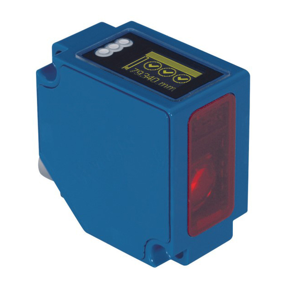
Summary of Contents for Wenglor OCP P0150E Series
- Page 1 OCPxxxP0150E High-performance distance sensors Operating instructions Available as PDF only Status: 11.12.2018 www.wenglor.com...
-
Page 2: Table Of Contents
Table of contents Intended Use Safety Precautions 2.1. Safety Precautions 2.2. Laser/LED warnings EU Declaration of Conformity Technical Data 4.1. Connection diagram 4.2. Housing dimensions 4.3. Control panel 4.4. Complementary products Assembly instructions Initial Operation 6.1. Operation using a controller without EDS file use 6.2. - Page 3 Detailed description of the object models for EtherNet/IP TM devices 8.1. Identity object (0x01) 8.2. Message router object (0x02) 8.3. Assembly object (0x04) 8.4. Connection manager object (0x06) 8.5. Port object (0xF4) 8.6. TCP/IP interface object (0xF5) 8.7. Ethernet link object (0xF6) 8.8.
-
Page 4: Intended Use
2.2. Laser/LED warnings Laser class 1 (EN 60825-1) LASER CLASS 1 standards and safety instructions EN60825-1 must be observed. 2007 3. EU Declaration of Conformity The EU declaration of conformity can be found on our website at www.wenglor.com in download area. RoHS... -
Page 5: Technical Data
4. Technical Data Order no. OCP801P0150E OCP162P0150E OCP352P0150E OCP662P0150E Working range 30…80mm 40…160mm 50…350mm 60…660mm Measuring Range 50mm 120mm 300mm 600mm Reproducibility 15…50µm 20…70µm 20…150µm 70…1000µm Linearity deviation 50…100µm 50…160µm 100…500µm 100…1000µm Temperature drift <5µm/K <10µm/K <20µm/K <50µm/K Output rate 330/s Light source Laser (red) - Page 6 Typical reproducibility curves in the working range OCP801P0150C OCP162P0150C 30 35 40 45 50 55 60 65 70 75 80 88 100 112 124 136 148 160 Working Range mm Working range mm OCP662P0150C OCP352P0150C 1000 60 120 180 240 300 360 420 480 540 600 660 50 80 110 140 170 200 230 260 290 320 350 Working Range mm Working Range mm...
-
Page 7: Connection Diagram
4.1. Connection diagram Legend Encoder A Platinum measuring resistor Encoder B Supply Voltage + not connected Supply Voltage 0 V Digital output MIN Test Input Digital output MAX Supply Voltage (AC Voltage) Test Input inverted Switching Output (NO) Digital output OK Trigger Input Switching Output (NC) -
Page 8: Control Panel
No connection established Device connected, connection established Green Device connected, connection established, communication active Green flashing 4.4. Complementary products wenglor offers Connection Technology for field wiring. Suitable mounting technology no. Suitable connection technology Midspan adapter Z0029 Junction with PoE ZAC50N0x... -
Page 9: Assembly Instructions
For a detailed description for different controllers and for installation of the files or project planning of the network refer to the help files of the relevant controller. wenglor provides a short exemplary instruction for com- device (www.wenglor.com Products Product search (order number) missioning of an EtherNet/IP ... -
Page 10: Functional Description Oled Display
7. Functional description OLED display Process Text Analyse Modus Network Display Rotate Intensity Normal Power star Screensaver High Resolution Middle Filter Illumination Value in µs Normal Output Rate Fast Laser Value in µm Measured Value E/A Test Nr. of Status Bit Status Bits Warmup Warmup... - Page 11 Fig. 1: Menu set language Press button to navigate: : Navigate to top. : Navigate to bottom. : Enter button. Press the Enter button to confirm the selection. Meaning of the menu items: : one level up in the menu. 3Back : switch to display mode.
-
Page 12: Run
7.1. Run Sensor switches to display mode. Order number OCP662P0150E Bar display of current measured value Status LEDs compared to the measurement range 79,340 mm Current measured value in mm Explanation of symbols of status LEDs: Meaning Condition 1 Condition 2 Condition 3 Symbol Symbol 1... -
Page 13: Display Intensity
7.2.2. Display intensity Intensity Adjusting the display intensity Min Min: The intensity of the display is set to a minimum value. Normal Normal: The intensity of the display is set to a medium value. Max Max.: The intensity of the display is set to a maximum value. ... -
Page 14: Exposure
7.5. Exposure The sensor automatically adjusts it exposure time or light pulse length to the object to be detected up to a maxi- mum value. In the preset DCM (Default Capture Mode) the sensor has a fixed, maximum possible exposure time. -
Page 15: I/O Test
7.8. I/O test This function manually changes the output of the sensor. It can be used to test whether the further process functions as required. The test is terminated automatically when exiting the test menu. This also occurs auto- matically if no button has been pressed for a period of 10 minutes. I/O test Testing the sensor outputs Measured value... -
Page 16: Network
7.9. Network Network Network parameter settings IP address IP address: Display of the IP address set. Subnet mask Subnet mask: Display of the Subnet mask set. Std gateway Std gateway: Display of the standard gateway set. 3 Back 7 Run 7.10. -
Page 17: Password
7.13. Password The password protection avoids an accidental amendment of the adjusted data. Password Setting the password function Activate Activate: Switching the password protection on or off. If the password protec- Change tion is activated, the operation of the sensor will be locked after inter- Lock ruption of the power supply and not released until successful entry of 3 Back... -
Page 18: Detailed Description Of The Object Models For Ethernet/Ip Tm Devices
Detailed description of the object models for EtherNet/IP devices 8.1. Identity object (0x01) This object provides the identification of the device. Identity object (object class ID 0x01) Class attributes Name Access Revision Max instance Number of instances Maximum ID number class attributes Maximum ID number instance attributes Class services Code... -
Page 19: Message Router Object (0X02)
8.2. Message router object (0x02) The message router defines the connection paths to other objects and allows access to the objects via these paths. Message router object (object class ID) Class attributes Name Access Revision Max instance Number of instances Optional attribute list Optional service list Maximum ID number class attributes... -
Page 20: Assembly Object (0X04)
8.3. Assembly object (0x04) The assembly object links attributes of different objects to allow for their transmission as a whole via a single connection. The following assemblies are available: • Input assembly (producing) 0x65 • Config assembly 0x64 Assembly object (object class ID 0x04) Class attributes Name Access... -
Page 21: Connection Manager Object (0X06)
8.4. Connection manager object (0x06) This object manages internal resources for maintaining explicit and implicit connections. Connection manager object (object class ID 0x06) Class attributes Name Access Revision Max instance Number of instances Optional attribute list Maximum ID number class attributes Maximum ID number instance attributes Class services Code... -
Page 22: Port Object (0Xf4)
8.5. Port object (0xF4) This object describes the existing CIP ports of the device. Port object (object class ID 0xF4) Class attributes Name Access Revision Max instance Number of instances Maximum ID number class attributes Maximum ID number instance attributes Entry port Port instance info Class services... -
Page 23: Tcp/Ip Interface Object (0Xf5)
8.6. TCP/IP interface object (0xF5) This object implements mechanisms for configuration of the TCP/IP layer such as, for example, IP address, subnet mask, and gateway address. TCP/IP interface object (object class ID 0xF5) Class attributes Name Access Revision Max instance Number of instances Maximum ID number class attributes Maximum ID number instance attributes... -
Page 24: Ethernet Link Object (0Xf6)
8.7. Ethernet link object (0xF6) This object configures the connection-specific properties (MAC-ID, Transmission rate etc.) of the Ethernet interfaces. Ethernet link object (object class ID 0xF6) Class attributes Name Access Revision Max instance Number of instances Maximum ID number class attributes Maximum ID number instance attributes Class services Code... -
Page 25: Qos Object (0X48)
8.8. QoS object (0x48) The QoS (Quality of Service) object can be used to configure the DSCP values of the different outgoing message priorities. QoS object (0x48) Class attributes Name Access Revision Max instance Number of instances Maximum ID number class attributes Maximum ID number instance attributes Class services Code... -
Page 26: Vendor-Specific Object (0X64)
8.9. Vendor-specific object (0x64) 8.9.1. Configuration assemblies Configuration assembly (assembly instance ID 0x64) for OCP Byte Bit 7 Bit 6 Bit 5 Bit 4 Bit 3 Bit 2 Bit 1 Bit 0 Filter Reserved Display Button Webser- Output Emitted rotate lock ver lock rate... -
Page 27: Static Input Assembly
8.9.2. Static input assembly The input assembly (input from the point of view of the controller) contains the process data of the sensors. Static input assembly (assembly instance ID 0x65) for OCP and OY2TA Byte Bit 7 Bit 6 Bit 5 Bit 4 Bit 3 Bit 2... - Page 28 Name EIP data type Access Values/default Filter USINT (8bit) Get/set 0 = Filter size 1 (dflt) 1 = Filter size 2 2 = Filter size 5 3 = Filter size 10 4 = Filter size 20 5 = Filter size 50 6 = Filter size 100 Emitted light BOOL (8bit)
- Page 29 Display language USINT (8bit) Get/set 0 = Deutsch 1 = English (dflt) 2 = Francais 3 = Espanol 4 = Italiano Constant: 0x2204 (µm) 3 Physical unit ENGUNIT (16bit) (Little Endian encoded) Instance services Code Name 0x01 Get_Attribute_All 0x0E Get_Attribute_Single 0x10 Set_Attribute_Single...
-
Page 30: Web-Based Configuration
9. Web-based configuration The device is equipped with a web-based set-up interface which operates independent of the operating sys- tem. Parameterizing of the device can conveniently be done using a standard web browser. In delivery condi- tion the device expects the IP address from a DHCP server. The web-based set-up interface is not required for normal operation on the controller. - Page 32 In order to now be able to open the website of the device (in the example OCP662P0150E), the IP address must be entered in the address bar of the browser as described Example: 192.168.100.10 The overview page Device general is not password protected. If the pages of the device or port settings are opened a password query appears.
-
Page 33: Page Structure
9.2. Page structure The webpage is divided in the following 4 areas: 1. Language selection: The language selection is used to change the webpage from English (delivery condition) to German, French, Spanish oder Italian. 2. Display: On every page the current display is shown as on the device itself. 3. -
Page 34: Device General
9.3. Device general After the connection has been established, the overview page "Device general" is displayed. 9.4. Device settings... -
Page 35: Measured Value Settings
Network settings If the device is not operated on a controller it is possible to change the network settings. By default, IP address assignment is done via a DHCP server. In delivery condition, the network setting is set to "Obtain IP address automatically". - Page 36 Exposure For a functional description of the exposure see chapter 7.5. Emitted Light For a functional description of the emitted light see chapter 7.7. Sensor settings reset A reset restores the factory settings of the display and measured value settings. Device test For a functional description of the device test see chapter 7.8.
-
Page 37: Maintenance Instructions
This operating manual is only a general description of technical processes whose implementation does not apply to every individual application.
Need help?
Do you have a question about the OCP P0150E Series and is the answer not in the manual?
Questions and answers