Table of Contents
Advertisement
Quick Links
www.ti.com
User's Guide
mmWaveICBoost and Antenna Module
Chethan Kumar Y.B.
The MMWAVEICBOOST Board is combined with the compatible antenna modules from the starter kit for
Industrial Radar Devices of the xWR68xx family.
Trademarks.................................................................................................................................................................................4
Started........................................................................................................................................................................5
1.1 Introduction........................................................................................................................................................................
Features......................................................................................................................................................................5
Included..................................................................................................................................................................7
2 MMWAVEICBOOST.................................................................................................................................................................
2.1
Hardware............................................................................................................................................................................9
Features............................................................................................................................................10
2.3 Muxing Scheme for Multiple Sources...............................................................................................................................
2.4 Using the MMWAVEICBOOST With the Starter Kit.........................................................................................................
DCA1000EVM...................................................................................................................................18
2.6 Power Connections..........................................................................................................................................................
2.7
Connectors.......................................................................................................................................................................19
2.8 Jumpers, Switches and LEDs..........................................................................................................................................
3.1
Hardware..........................................................................................................................................................................31
3.2 xWR6843ISK/IWR6843ISK-ODS Block Diagram............................................................................................................
3.3 PCB Storage and Handling Recommendations...............................................................................................................
3.4 Power Connections..........................................................................................................................................................
3.5 Interfaces.........................................................................................................................................................................
3.6 xWR6843ISK Antenna.....................................................................................................................................................
3.7 IWR6843ISK-ODS Antenna.............................................................................................................................................
3.8 Modular Mode..................................................................................................................................................................
Mode........................................................................................................................................................46
4 xWR6843AOPEVM Rev F.....................................................................................................................................................
4.1
Hardware..........................................................................................................................................................................48
Diagram..................................................................................................................................................................49
4.3 PCB Storage and Handling Recommendations...............................................................................................................
4.4 Heat Sink and Temperature.............................................................................................................................................
Antenna............................................................................................................................................53
Settings.................................................................................................................................................................55
4.7 xWR6843AOPEVM Muxing Scheme...............................................................................................................................
4.9 PC Connection.................................................................................................................................................................
Compliance.......................................................................................................................................................60
5 IWR6843ISK / IWR6843ISK-ODS (deprecated)...................................................................................................................
5.1
Hardware..........................................................................................................................................................................61
5.2 IWR6843ISK/IWR6843ISK-ODS Block Diagram.............................................................................................................
5.3 PCB Storage and Handling Recommendations...............................................................................................................
5.4 Power Connections..........................................................................................................................................................
LEDs..................................................................................................................................................65
5.6 IWR6843ISK Antenna......................................................................................................................................................
5.7 IWR6843ISK-ODS Antenna.............................................................................................................................................
SWRU546D - OCTOBER 2018 - REVISED NOVEMBER 2020
Submit Document Feedback
ABSTRACT
Table of Contents
C.............................................................................................................................31
Mode.............................................................................................................................................46
Mode..........................................................................................................................56
Copyright © 2020 Texas Instruments Incorporated
Table of Contents
mmWaveICBoost and Antenna Module
5
9
11
15
19
26
34
34
34
35
39
42
44
48
50
50
56
59
61
64
64
64
66
68
1
Advertisement
Table of Contents

Related Manuals for Texas Instruments MMWAVEICBOOST


Summary of Contents for Texas Instruments MMWAVEICBOOST
-
Page 1: Table Of Contents
Table of Contents User’s Guide mmWaveICBoost and Antenna Module Chethan Kumar Y.B. ABSTRACT The MMWAVEICBOOST Board is combined with the compatible antenna modules from the starter kit for Industrial Radar Devices of the xWR68xx family. Table of Contents Trademarks....................................4 1 Getting Started..................................5... - Page 2 Rear..................................14 Figure 2-7. Front..................................Figure 2-8. Uninstalled Devices..............................15 Figure 2-9. COM Ports After the Driver Installation........................Figure 2-10. Integration of MMWAVEICBOOST and Starter Kit....................Figure 2-11. Mechanical Mounting of the PCB.......................... Figure 2-12. IWR6843ISK-MMWAVEICBOOST-DCA1000EVM Test Setup................18 Figure 2-13. Power Connector..............................19 Figure 2-14.
- Page 3 Figure 4-11. xWR6843AOPEVM Switches..........................Figure 4-12. Switch Configuration for Modular Mode........................ Figure 4-13. Switch Configuration for Bluetooth Mode......................Figure 4-14. xWR6843AOPEVM Mounted on MMWAVEICBOOST..................58 Figure 4-15. Switch Configuration for MMWAVEICBOOST Mode.....................59 Figure 4-16. SICP2015 COM Ports............................Figure 5-1. IWR6843ISK Front View............................61 Figure 5-2.
-
Page 4: Trademarks
Table 3-2. IWR6843ISK I2C Devices and Address........................38 Table 3-3. S1 Config Flashing and Functional Mode......................... Table 3-4. S1 Config for DCA1000EVM mode...........................46 Table 3-5. S1 Config for mmWAVEICBOOST mode........................47 Table 4-1. Switches..................................55 Table 4-2. Pin Mux Settings............................... Table 4-3. SOP Configuration.............................. -
Page 5: Getting Started
This board contains 60-GHz mmWave Radar transceiver in which antennas are etched on PCB or on packager and act as the Radar front-end board. The MMWAVEICBOOST is an add-on board used with TI's mmWave sensor used in all starter kits to provide more interfaces and PC connectivity to the mmWave sensors. - Page 6 60-pin, high-density (HD) connector for raw analog-to-digital converter (ADC) data over LVDS and trace data capability • Long range on-board antenna • Current sensors for all rails • On-board PMIC mmWaveICBoost and Antenna Module SWRU546D – OCTOBER 2018 – REVISED NOVEMBER 2020 Submit Document Feedback Copyright © 2020 Texas Instruments Incorporated...
-
Page 7: What's Included
One Micro USB cable for connecting to PC • Standoffs, screws and nuts for the standalone printed circuit board testing or for mating purpose • Jumpers SWRU546D – OCTOBER 2018 – REVISED NOVEMBER 2020 mmWaveICBoost and Antenna Module Submit Document Feedback Copyright © 2020 Texas Instruments Incorporated... - Page 8 UL, CSA, VDE, CCC, PSE, and more. The length of the power cable should be < 3 m. mmWaveICBoost and Antenna Module SWRU546D – OCTOBER 2018 – REVISED NOVEMBER 2020 Submit Document Feedback Copyright © 2020 Texas Instruments Incorporated...
-
Page 9: Mmwaveicboost
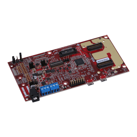
2.1 Hardware Figure 2-1 Figure 2-2 shows the front and rear view of EVM, respectively. Figure 2-1. MMWAVEICBOOST Front View Figure 2-2. MMWAVEICBOOST Rear View SWRU546D – OCTOBER 2018 – REVISED NOVEMBER 2020 mmWaveICBoost and Antenna Module Submit Document Feedback... -
Page 10: Block Diagram And Features
HEADER HEADER LOADSW LOADSW LM536255 HEADER > 5 V to 36 V Figure 2-3. Block Diagram of MMWAVEICBOOST 2.2.2 Hardware Features • 1 Micro USB connector for XDS110 Emulator/UART interface • 1 Micro USB connector for FTDI interface • One 12-pin dip switch for mux controls •... -
Page 11: Muxing Scheme For Multiple Sources
40 pin LP/BP, DCA1000 EVM, onboard FTDI and XDS110 that can control the Radar front-end chip in the starter kit. This is done with the help of mux scheme implemented on the MMWAVEICBOOST. Follow the switch settings as shown in Table 2-1 to avoid the conflicts. -
Page 12: Switch Settings
(Default Position) Position Designator for STAND ALONE Mode Position for DCA1000 Mode Position for 40-Pin LP/BP S1.12 S1.11 S1.10 S1.9 S1.8 mmWaveICBoost and Antenna Module SWRU546D – OCTOBER 2018 – REVISED NOVEMBER 2020 Submit Document Feedback Copyright © 2020 Texas Instruments Incorporated... - Page 13 S1.4 S1.3 S1.2 S1.1 Standalone mode means starter kit and MMWAVEICBOOST connected together. S1.5 has RS232 connections from 40 pin/FTDI/60 pin/XDS110, ON postion routes UART to XDS110 (Application/user UART COM port). SWRU546D – OCTOBER 2018 – REVISED NOVEMBER 2020 mmWaveICBoost and Antenna Module Submit Document Feedback Copyright ©...
-
Page 14: Figure 2-5. Front
Table 2-2. Mux Selection Images Front Rear Whole Board Figure 2-5. Front Figure 2-6. Rear Zoomed IN Figure 2-7. Front mmWaveICBoost and Antenna Module SWRU546D – OCTOBER 2018 – REVISED NOVEMBER 2020 Submit Document Feedback Copyright © 2020 Texas Instruments Incorporated... -
Page 15: Using The Mmwaveicboost With The Starter Kit
MMWAVEICBOOST 2.4 Using the MMWAVEICBOOST With the Starter Kit The MMWAVEICBOOST board is required with the starter kit for the following use cases: • PC connection is enabled for communicating with the mmWave front end chip • Connecting to mmWave Studio (mmWave Studio is a tool that provides capability to configure the MMWAVEICBOOST front end from the PC). -
Page 16: Figure 2-9. Com Ports After The Driver Installation
2.4.3 MMWAVEICBOOST and Antenna Module Connections for Modular Testing A compatible antenna module can be stacked on top of the MMWAVEICBOOST board using the two 60-pin HD connectors and 12 nuts, four washers, and four M3 screws (for improving the thermal performance). Connectors... -
Page 17: Figure 2-10. Integration Of Mmwaveicboost And Starter Kit
MMWAVEICBOOST Figure 2-10. Integration of MMWAVEICBOOST and Starter Kit 2.4.4 Figure 2-11 shows the mechanical mounting of PCB. Spacers and screws can be used as heat sinking elements to spread the heat from the starter kit to carrier board, as shown in Figure 2-11. -
Page 18: Interfacing With The Dca1000Evm
PC as the MMWAVEICBOOST and antenna module. A 60-pin Samtec cable (HQCD-030-02.00-SEU- TBR-1) is used to connect the 60-pin connector (J10) on the MMWAVEICBOOST to the J3 input connector on the DCA1000 EVM. Mount the four stand offs, four washers, and pan head screws to mate with the DCA1000EVM. -
Page 19: Power Connections
Open(2-3): Input voltage is 5V(Default) Figure 2-16. J27 Header 2.7 Connectors There are several types of connectors used in the MMWAVEICBOOST board, which are mentioned below. SWRU546D – OCTOBER 2018 – REVISED NOVEMBER 2020 mmWaveICBoost and Antenna Module Submit Document Feedback... -
Page 20: Figure 2-17. Ti Standard Launchpad
MMWAVEICBOOST www.ti.com 2.7.1 20-Pin LaunchPad and Booster Pack Connectors (J5, J6) The MMWAVEICBOOST has the standard LaunchPad connectors (J5 and J6) that enable it to be directly connected to all TI MCU LaunchPad's pinout, as shown in Figure 2-17. While connecting the MMWAVEICBOOST to other LaunchPads, ensure the pin-1 orientation is correct by matching the 3V3 and 5-V signal marking on the boards. -
Page 21: Figure 2-18. 60-Pin Hd Connectors
UART, I2C, NRST, NERR, and SOPs) and JTAG debug signals from the starter kit. The Trace and DMM interface lines are also available through this connector. Figure 2-18. 60-Pin HD Connectors SWRU546D – OCTOBER 2018 – REVISED NOVEMBER 2020 mmWaveICBoost and Antenna Module Submit Document Feedback Copyright © 2020 Texas Instruments Incorporated... - Page 22 MSS_LOGGER LVDS_0M SPI_CS1 PMIC_CLKOUT/SOP2 SPI_CLK1 WARMRST SYNC_IN NERRIN SPI_MOSI1 SYNC_OUT/SOP1 NERROUT SPI_MISO1 GPIO_0 RS232_RX LVDS_FRCLKP GPIO_1 RS232_TX LVDS_FRCLKM GPIO_2 mmWaveICBoost and Antenna Module SWRU546D – OCTOBER 2018 – REVISED NOVEMBER 2020 Submit Document Feedback Copyright © 2020 Texas Instruments Incorporated...
- Page 23 Pin Number Pin Description LVDS_3P VPP_1.7V LVDS_3M 3.3V LVDS_2P 3.3V LVDS_2M PMIC_EN DP10 DP11 LVDS_VALIDP DP12 LVDS_VALIDM DP13 DP14 DP15 SWRU546D – OCTOBER 2018 – REVISED NOVEMBER 2020 mmWaveICBoost and Antenna Module Submit Document Feedback Copyright © 2020 Texas Instruments Incorporated...
-
Page 24: Figure 2-19. 60-Pin Hd Connector (Dca1000)
JTAG Debugger should not be connected on the 14-pin connector. Figure 2-20. 60-Pin MIPI Connector mmWaveICBoost and Antenna Module SWRU546D – OCTOBER 2018 – REVISED NOVEMBER 2020 Submit Document Feedback Copyright © 2020 Texas Instruments Incorporated... -
Page 25: Figure 2-21. 14-Pin Jtag Connector
CAN1_TX J1 pin 1 (CAN1 corresponds to CANFD) MOSI_1 CAN1_RX J1 pin 3 Figure 2-22 shows the CAN connectors. SWRU546D – OCTOBER 2018 – REVISED NOVEMBER 2020 mmWaveICBoost and Antenna Module Submit Document Feedback Copyright © 2020 Texas Instruments Incorporated... -
Page 26: Jumpers, Switches And Leds
001 (SOP mode 4) = functional mode SOP2 101 (SOP mode 5) = flash programming Figure 2-24 shows the SOP jumpers. mmWaveICBoost and Antenna Module SWRU546D – OCTOBER 2018 – REVISED NOVEMBER 2020 Submit Document Feedback Copyright © 2020 Texas Instruments Incorporated... -
Page 27: Figure 2-24. Sop Jumpers
USB connector, or from the 40-pin LaunchPad, as shown in Table 2-12. 3.3 V is for the starter kits and the rest of the board to operate. SWRU546D – OCTOBER 2018 – REVISED NOVEMBER 2020 mmWaveICBoost and Antenna Module Submit Document Feedback Copyright © 2020 Texas Instruments Incorporated... -
Page 28: Figure 2-25. J13 Header
DMM trace header 1 JTAG trace signals. Onboard 16-pin header provides external user control for DMM trace header 2 JTAG trace signals. mmWaveICBoost and Antenna Module SWRU546D – OCTOBER 2018 – REVISED NOVEMBER 2020 Submit Document Feedback Copyright © 2020 Texas Instruments Incorporated... -
Page 29: Figure 2-26. Sw1
40 pin and FTDI ON : FTDI (default) OFF : 14 pin S1.12 XDS110/14 pin ON : XDS110 (default) SWRU546D – OCTOBER 2018 – REVISED NOVEMBER 2020 mmWaveICBoost and Antenna Module Submit Document Feedback Copyright © 2020 Texas Instruments Incorporated... -
Page 30: Figure 2-29. Ds1
5-V supply indication if the input voltage to board is Green POWER more than 5 V Figure 2-33. D11 & D14 Green POWER 3V3 supply indication mmWaveICBoost and Antenna Module SWRU546D – OCTOBER 2018 – REVISED NOVEMBER 2020 Submit Document Feedback Copyright © 2020 Texas Instruments Incorporated... -
Page 31: Xwr6843Isk / Iwr6843Isk-Ods Rev C
In accordance to the EN 62311 RF exposure test, a minimum separation distance of 20 centimeters should be maintained between the user and the EVM during operation. Figure 3-1. xWR6843ISK Front View SWRU546D – OCTOBER 2018 – REVISED NOVEMBER 2020 mmWaveICBoost and Antenna Module Submit Document Feedback Copyright © 2020 Texas Instruments Incorporated... -
Page 32: Figure 3-2. Xwr6843Isk Rear View
In accordance to the EN 62311 RF exposure test, a minimum separation distance of 20 centimeters should be maintained between the user and the EVM during operation. mmWaveICBoost and Antenna Module SWRU546D – OCTOBER 2018 – REVISED NOVEMBER 2020 Submit Document Feedback Copyright © 2020 Texas Instruments Incorporated... -
Page 33: Figure 3-3. Pcb Antenna - Top
/ IWR6843ISK-ODS REV C Figure 3-3. PCB Antenna – Top Figure 3-4. PCB Antenna – Bottom SWRU546D – OCTOBER 2018 – REVISED NOVEMBER 2020 mmWaveICBoost and Antenna Module Submit Document Feedback Copyright © 2020 Texas Instruments Incorporated... -
Page 34: Xwr6843Isk/Iwr6843Isk-Ods Block Diagram
3.4.1 Higher Power Applications For higher power application tespoint T13 (5V) and T12 (GND) can be used to supply power the EVM. mmWaveICBoost and Antenna Module SWRU546D – OCTOBER 2018 – REVISED NOVEMBER 2020 Submit Document Feedback Copyright © 2020 Texas Instruments Incorporated... -
Page 35: Interfaces
/ IWR6843ISK-ODS REV C 3.5 Interfaces SWRU546D – OCTOBER 2018 – REVISED NOVEMBER 2020 mmWaveICBoost and Antenna Module Submit Document Feedback Copyright © 2020 Texas Instruments Incorporated... - Page 36 Muxes USER UART to 60 pin header J1 Muxes USER UART to USB connector J5 S1.6 Reset Switch GPIO1 toggle switch mmWaveICBoost and Antenna Module SWRU546D – OCTOBER 2018 – REVISED NOVEMBER 2020 Submit Document Feedback Copyright © 2020 Texas Instruments Incorporated...
-
Page 37: Figure 3-6. Led Location And Color
Indicates the application of 5V power Green GPIO 2 Connected to GPIO2, can be used when GPIO is set as output SWRU546D – OCTOBER 2018 – REVISED NOVEMBER 2020 mmWaveICBoost and Antenna Module Submit Document Feedback Copyright © 2020 Texas Instruments Incorporated... -
Page 38: Figure 3-7. Can Connector Location And Label
Reference Designator Part Number Slave Address Temperature Sensor TMP112AQDRLRQ1 100 1011 EEPROM CAT24C08WI-GT3 101 00XX Current sensor1 INA226AIDGST 100 0000 mmWaveICBoost and Antenna Module SWRU546D – OCTOBER 2018 – REVISED NOVEMBER 2020 Submit Document Feedback Copyright © 2020 Texas Instruments Incorporated... -
Page 39: Xwr6843Isk Antenna
The xWR6843ISK includes onboard-etched long range antennas for the four receivers and three transmitters. Figure 3-8 shows the PCB antennas. Figure 3-8. PCB Antennas SWRU546D – OCTOBER 2018 – REVISED NOVEMBER 2020 mmWaveICBoost and Antenna Module Submit Document Feedback Copyright © 2020 Texas Instruments Incorporated... -
Page 40: Figure 3-9. Iwr6843Isk Antenna Placement Mimo Array
All of the measurements were done with a Tx and Rx combination together. Thus, for the -6dB beam width, you must see a -12db (Tx (-6dB) + Rx(-6dB)) number. mmWaveICBoost and Antenna Module SWRU546D – OCTOBER 2018 – REVISED NOVEMBER 2020 Submit Document Feedback Copyright © 2020 Texas Instruments Incorporated... -
Page 41: Figure 3-10. Tx1 Antenna Radiation Pattern In
Figure 3-13. TX1 Antenna Radiation Pattern in Azimuth Elevation Figure 3-14. TX2 Antenna Radiation Pattern in Figure 3-15. TX3 Antenna Radiation Pattern in Elevation Elevation SWRU546D – OCTOBER 2018 – REVISED NOVEMBER 2020 mmWaveICBoost and Antenna Module Submit Document Feedback Copyright © 2020 Texas Instruments Incorporated... -
Page 42: Iwr6843Isk-Ods Antenna
Figure 3-18 shows combined Antenna Radiation pattern in the Azimuth plane for all the transmitter and receiver pairs together (TX[1-3]-RX[1-4]). mmWaveICBoost and Antenna Module SWRU546D – OCTOBER 2018 – REVISED NOVEMBER 2020 Submit Document Feedback Copyright © 2020 Texas Instruments Incorporated... - Page 43 / IWR6843ISK-ODS REV C Figure 3-18. Measured Azimuthal Radiation Pattern for All Tx to Rx Pairs (All 12 Virtual Antenna Pairs Included) SWRU546D – OCTOBER 2018 – REVISED NOVEMBER 2020 mmWaveICBoost and Antenna Module Submit Document Feedback Copyright © 2020 Texas Instruments Incorporated...
-
Page 44: Modular Mode
When enumerated correctly, the 2 UART ports are displayed on the device manager as a Virtual COM Port, similar to that shown in Figure 3-20. Figure 3-20. Virtual COM port mmWaveICBoost and Antenna Module SWRU546D – OCTOBER 2018 – REVISED NOVEMBER 2020 Submit Document Feedback Copyright © 2020 Texas Instruments Incorporated... -
Page 45: Table 3-3. S1 Config Flashing And Functional Mode
S1 switch setting for functional and flashing mode is shown in Table 3-3. Table 3-3. S1 Config Flashing and Functional Mode s1.1 s1.2 s1.3 s1.4 s1.5 s1.6 Flashing Functional SWRU546D – OCTOBER 2018 – REVISED NOVEMBER 2020 mmWaveICBoost and Antenna Module Submit Document Feedback Copyright © 2020 Texas Instruments Incorporated... -
Page 46: Dca1000Evm Mode
In this mode the boards are setup as shown in Figure 3-23, UART is routed to the 60 pin connector to the XDS110 USB. More on the mmWAVEICBOOST, setup and features it provides can be found in Section 2 mmWaveICBoost and Antenna Module SWRU546D –... -
Page 47: Table 3-5. S1 Config For Mmwaveicboost Mode
/ IWR6843ISK-ODS REV C Figure 3-23. mmWAVEICBOOST mode S1 switch settings for mmWAVEICBOOST mode is shown in Table 3-5 Table 3-5. S1 Config for mmWAVEICBOOST mode S1.1 S1.2 S1.3 S1.4 S1.5 S1.6 mmWAVEICBOO ST mode SWRU546D – OCTOBER 2018 – REVISED NOVEMBER 2020... -
Page 48: Xwr6843Aopevm Rev F
60-GHz to 64-GHz mmWave sensing for form-factor deployment and testing • Functional and flashing SOP Mode • Emulator USB port for user UART and Data COM ports mmWaveICBoost and Antenna Module SWRU546D – OCTOBER 2018 – REVISED NOVEMBER 2020 Submit Document Feedback Copyright © 2020 Texas Instruments Incorporated... -
Page 49: Block Diagram
The Breakaway board sections contain the 60-pin Samtec connector for interfacing with the MMWAVEICBOOST. Figure 4-3. Block Diagram of the xWR6843AOPEVM SWRU546D – OCTOBER 2018 – REVISED NOVEMBER 2020 mmWaveICBoost and Antenna Module Submit Document Feedback Copyright © 2020 Texas Instruments Incorporated... -
Page 50: Pcb Storage And Handling Recommendations
The CAD drawing for the heat sink is shown in Figure 4-5 mmWaveICBoost and Antenna Module SWRU546D – OCTOBER 2018 – REVISED NOVEMBER 2020 Submit Document Feedback Copyright © 2020 Texas Instruments Incorporated... - Page 51 Rev F Figure 4-5. Heat sink CAD drawing Application of the heat sink is shown in Figure 4-6 SWRU546D – OCTOBER 2018 – REVISED NOVEMBER 2020 mmWaveICBoost and Antenna Module Submit Document Feedback Copyright © 2020 Texas Instruments Incorporated...
- Page 52 Rev F www.ti.com Figure 4-6. Heat sink placement mmWaveICBoost and Antenna Module SWRU546D – OCTOBER 2018 – REVISED NOVEMBER 2020 Submit Document Feedback Copyright © 2020 Texas Instruments Incorporated...
-
Page 53: Xwr6843Aopevm Antenna
Figure 4-7 shows the antenna on package. Figure 4-7. AOP Antennas Figure 4-8. IWR6843AOP antenna placement MIMO array SWRU546D – OCTOBER 2018 – REVISED NOVEMBER 2020 mmWaveICBoost and Antenna Module Submit Document Feedback Copyright © 2020 Texas Instruments Incorporated... - Page 54 Included) Figure 4-10. Measured Elevation Radiation Pattern for All Tx to Rx Pairs (All 12 Virtual Antenna Pairs Included) mmWaveICBoost and Antenna Module SWRU546D – OCTOBER 2018 – REVISED NOVEMBER 2020 Submit Document Feedback Copyright © 2020 Texas Instruments Incorporated...
-
Page 55: Switch Settings
Bluetooth Enable Bluetooth Disable S2.4 Not Connected Not Connected SOP2 Pulled up SOP2 Pulled down Reset switch User switch SWRU546D – OCTOBER 2018 – REVISED NOVEMBER 2020 mmWaveICBoost and Antenna Module Submit Document Feedback Copyright © 2020 Texas Instruments Incorporated... -
Page 56: Xwr6843Aopevm Muxing Scheme
SOP mode is set by the MMWAVEICBOOST. 4.8 Modular and MMWAVEICBOOST Mode The IWR6843AOP can be used in modular mode or mounted on the MMWAVEICBOOST for debugging. 4.8.1 Modular Mode When used in Modular mode, the UART can either be routed to the SICP2015, which displays the data on the mmWave visualizer, or to other devices connected to the USB interface. - Page 57 Rev F Figure 4-12. Switch Configuration for Modular Mode SWRU546D – OCTOBER 2018 – REVISED NOVEMBER 2020 mmWaveICBoost and Antenna Module Submit Document Feedback Copyright © 2020 Texas Instruments Incorporated...
- Page 58 Figure 4-13. Switch Configuration for Bluetooth Mode 4.8.2 MMWAVEICBOOST Mode This mode enables access to debugging tools available on the MMWAVEICBOOST such as the JTAG, ADC capture, CAN, LaunchPad connector, and so forth. Figure 4-14. xWR6843AOPEVM Mounted on MMWAVEICBOOST mmWaveICBoost and Antenna Module SWRU546D –...
-
Page 59: Pc Connection
For mounted mode, the UART should be routed to the 60-pin connector. Set up the device as shown in Figure 4-15. When mounted as shown, the SOP mode is overridden by the MMWAVEICBOOST SOP configuration. Figure 4-15. Switch Configuration for MMWAVEICBOOST Mode 4.9 PC Connection... -
Page 60: Reach Compliance
6. Load image to serial flash. 4.9.3 DCA1000 For data capture using the DCA1000, set up the board to MMWAVEICBOOST mode, having the SOP and UART muxed set correctly. Continue as you would with the IWR6843ISK. For more information, see Section 2.5.3. -
Page 61: Iwr6843Isk / Iwr6843Isk-Ods (Deprecated)
In accordance to the EN 62311 RF exposure test, a minimum separation distance of 20 centimeters should be maintained between the user and the EVM during operation. Figure 5-1. IWR6843ISK Front View SWRU546D – OCTOBER 2018 – REVISED NOVEMBER 2020 mmWaveICBoost and Antenna Module Submit Document Feedback Copyright © 2020 Texas Instruments Incorporated... - Page 62 In accordance to the EN 62311 RF exposure test, a minimum separation distance of 20 centimeters should be maintained between the user and the EVM during operation. mmWaveICBoost and Antenna Module SWRU546D – OCTOBER 2018 – REVISED NOVEMBER 2020 Submit Document Feedback Copyright © 2020 Texas Instruments Incorporated...
- Page 63 IWR6843ISK / IWR6843ISK-ODS (deprecated) Figure 5-3. PCB Antenna – Top Figure 5-4. PCB Antenna – Bottom SWRU546D – OCTOBER 2018 – REVISED NOVEMBER 2020 mmWaveICBoost and Antenna Module Submit Document Feedback Copyright © 2020 Texas Instruments Incorporated...
-
Page 64: Iwr6843Isk/Iwr6843Isk-Ods Block Diagram
After the 3.3-V supply is provided to the EVM, TI recommends toggling the NRST signal once to ensure a reliable boot-up state; this signal is accessible on the 60-pin HD connector. mmWaveICBoost and Antenna Module SWRU546D – OCTOBER 2018 – REVISED NOVEMBER 2020 Submit Document Feedback Copyright © 2020 Texas Instruments Incorporated... -
Page 65: Miscellaneous And Leds
Reference Designator Part Number Slave Address Temperature Sensor TMP112AQDRLRQ1 100 1011 EEPROM CAT24C08WI-GT3 101 00XX Current sensor1 INA226AIDGST 100 0000 SWRU546D – OCTOBER 2018 – REVISED NOVEMBER 2020 mmWaveICBoost and Antenna Module Submit Document Feedback Copyright © 2020 Texas Instruments Incorporated... -
Page 66: Iwr6843Isk Antenna
-12db (Tx (-6dB) + Rx(-6dB)) number. Figure 5-8. TX1 Antenna Radiation Pattern in Figure 5-9. TX2 Antenna Radiation Pattern in Azimuth Azimuth mmWaveICBoost and Antenna Module SWRU546D – OCTOBER 2018 – REVISED NOVEMBER 2020 Submit Document Feedback Copyright © 2020 Texas Instruments Incorporated... - Page 67 Figure 5-11. TX1 Antenna Radiation Pattern in Azimuth Elevation Figure 5-12. TX2 Antenna Radiation Pattern in Figure 5-13. TX3 Antenna Radiation Pattern in Elevation Elevation SWRU546D – OCTOBER 2018 – REVISED NOVEMBER 2020 mmWaveICBoost and Antenna Module Submit Document Feedback Copyright © 2020 Texas Instruments Incorporated...
-
Page 68: Iwr6843Isk-Ods Antenna
(TX[1-3]-RX[1-4]). Figure 5-15. Measured Azimuthal Radiation Pattern for All Tx to Rx Pairs (All 12 Virtual Antenna Pairs Included) mmWaveICBoost and Antenna Module SWRU546D – OCTOBER 2018 – REVISED NOVEMBER 2020 Submit Document Feedback Copyright © 2020 Texas Instruments Incorporated... - Page 69 TX[1-3]-RX[1-4]. Figure 5-16. Measured Elevation Radiation Pattern for All Tx to Rx Pairs (All 12 Virtual Antenna Pairs Included) SWRU546D – OCTOBER 2018 – REVISED NOVEMBER 2020 mmWaveICBoost and Antenna Module Submit Document Feedback Copyright © 2020 Texas Instruments Incorporated...
- Page 70 In accordance to the EN 62311 RF exposure test, a minimum separation distance of 20 centimeters should be maintained between the user and the EVM during operation. Figure 6-1. IWR6843AOPEVM Top View mmWaveICBoost and Antenna Module SWRU546D – OCTOBER 2018 – REVISED NOVEMBER 2020 Submit Document Feedback Copyright © 2020 Texas Instruments Incorporated...
- Page 71 TI radar system, PMIC, SFLASH, SOP configuration, Filter, TI mmWave Radar chip, and a USB to UART converter. The Breakaway board sections contain the 60-pin Samtec connector for interfacing with the MMWAVEICBOOST. SWRU546D – OCTOBER 2018 – REVISED NOVEMBER 2020 mmWaveICBoost and Antenna Module Submit Document Feedback Copyright © 2020 Texas Instruments Incorporated...
-
Page 72: Iwr6843Aopevm Antenna
The IWR6843AOPEVM includes four receiver and three transmitter short range antennas on the package of the chip. Figure 6-4 shows the antenna on package. mmWaveICBoost and Antenna Module SWRU546D – OCTOBER 2018 – REVISED NOVEMBER 2020 Submit Document Feedback Copyright © 2020 Texas Instruments Incorporated... - Page 73 IWR6843AOPEVM (Deprecated) Figure 6-4. AOP Antennas SWRU546D – OCTOBER 2018 – REVISED NOVEMBER 2020 mmWaveICBoost and Antenna Module Submit Document Feedback Copyright © 2020 Texas Instruments Incorporated...
- Page 74 Included) Figure 6-6. Measured Elevation Radiation Pattern for All Tx to Rx Pairs (All 12 Virtual Antenna Pairs Included) mmWaveICBoost and Antenna Module SWRU546D – OCTOBER 2018 – REVISED NOVEMBER 2020 Submit Document Feedback Copyright © 2020 Texas Instruments Incorporated...
-
Page 75: Table 6-1. Switches
Bluetooth Disable SW1-1 SOP1 pull up SOP1 pull down SW1-2 SOP0 pull down SOP0 pull up Reset switch User switch SWRU546D – OCTOBER 2018 – REVISED NOVEMBER 2020 mmWaveICBoost and Antenna Module Submit Document Feedback Copyright © 2020 Texas Instruments Incorporated... -
Page 76: Iwr6843Aopevm Muxing Scheme
MMWAVEICBOOST. 6.7 Modular and MMWAVEICBOOST Mode The IWR6843AOP can be used in modular mode or mounted on the MMWAVEICBOOST for debugging. 6.7.1 Modular Mode When used in modular mode, the UART can either be routed to the SICP2015, which displays the data on the mmWave visualizer, or to other devices connected to the USB interface. - Page 77 IWR6843AOPEVM (Deprecated) Figure 6-8. Switch Configuration for Modular Mode Figure 6-9. Switch Configuration for BT Mode SWRU546D – OCTOBER 2018 – REVISED NOVEMBER 2020 mmWaveICBoost and Antenna Module Submit Document Feedback Copyright © 2020 Texas Instruments Incorporated...
- Page 78 IWR6843AOPEVM (Deprecated) www.ti.com 6.7.2 MMWAVEICBOOST Mode This mode enables access to debugging tools available on the MMWAVEICBOOST such as the JTAG, ADC capture, CAN, LaunchPad connector, and so forth. mmWaveICBoost and Antenna Module SWRU546D – OCTOBER 2018 – REVISED NOVEMBER 2020 Submit Document Feedback Copyright ©...
- Page 79 For mounted mode, the UART should be routed to the 60-pin connector. Set up the device as shown in Figure 6-10. When mounted as shown, the SOP mode is overridden by the MMWAVEICBOOST SOP configuration. Figure 6-10. Switch Configuration for MMWAVEICBOOST Mode When mounted and setup correctly, the MMWAVEICBOOST can be used same as the IWR6843ISK and IWR6843ODS with DCA1000EVM, LaunchPads, and so forth.
-
Page 80: Reach Compliance
In compliance with the Article 33 provision of the EU REACH regulation, this is to notify you that this EVM includes component(s) containing at least one substance of very high concern (SVHC) above 0.1%. The uses from Texas Instruments do not exceed 1 ton per year. The SVHC’s are: Component... -
Page 81: Ti E2E Community
Page • Added Note to xWR6843ISK / IWR6843ISK-ODS REV C section..............• Added Note to xWR6843AOPEVM Rev F section....................48 SWRU546D – OCTOBER 2018 – REVISED NOVEMBER 2020 mmWaveICBoost and Antenna Module Submit Document Feedback Copyright © 2020 Texas Instruments Incorporated... - Page 82 TI products. TI’s provision of these resources does not expand or otherwise alter TI’s applicable warranties or warranty disclaimers for TI products. Mailing Address: Texas Instruments, Post Office Box 655303, Dallas, Texas 75265 Copyright © 2020, Texas Instruments Incorporated...
Need help?
Do you have a question about the MMWAVEICBOOST and is the answer not in the manual?
Questions and answers