
Related Manuals for Texas Instruments LaunchPad MSP-EXP430F5529LP


Summary of Contents for Texas Instruments LaunchPad MSP-EXP430F5529LP
- Page 1 MSP-EXP430F5529LP LaunchPad™ Development Kit User's Guide Literature Number: SLAU533B September 2013 – Revised June 2014...
-
Page 2: Table Of Contents
F5529 Code Examples .................... MSP430 Application Notes ..................... TI E2E Community ....................Community at Large ..........................FAQs ........................Schematics .......................... Revision History Table of Contents SLAU533B – September 2013 – Revised June 2014 Submit Documentation Feedback Copyright © 2013–2014, Texas Instruments Incorporated... - Page 3 ......................Schematics (1 of 4) ......................Schematics (2 of 4) ......................Schematics (3 of 4) ......................Schematics (4 of 4) SLAU533B – September 2013 – Revised June 2014 List of Figures Submit Documentation Feedback Copyright © 2013–2014, Texas Instruments Incorporated...
- Page 4 ................Backchannel Library: Constants to Configure ..................Backchannel Library: Functions ......................Clock Settings ..............How MSP430 Device Documentation is Organized List of Tables SLAU533B – September 2013 – Revised June 2014 Submit Documentation Feedback Copyright © 2013–2014, Texas Instruments Incorporated...
-
Page 5: Getting Started
You can either design your own BoosterPack or choose among many already available from TI and third-party developers. LaunchPad, BoosterPack, Code Composer Studio are trademarks of Texas Instruments. IAR Embedded Workbench is a trademark of IAR Systems. -
Page 6: Key Features
(3.3 V and 5 V) on the isolation jumper block be connected. These supply power to the target F5529 device. As shipped from TI, these jumpers are connected. MSP-EXP430F5529LP LaunchPad™ Development Kit User's Guide SLAU533B – September 2013 – Revised June 2014 Submit Documentation Feedback Copyright © 2013–2014, Texas Instruments Incorporated... -
Page 7: Jumper Requirements Necessary For Software Demo
When you attach the LaunchPad to the PC, a storage volume is mounted on the host. This volume can be seen in "My Computer", with the name "F5529LP": SLAU533B – September 2013 – Revised June 2014 MSP-EXP430F5529LP LaunchPad™ Development Kit User's Guide Submit Documentation Feedback Copyright © 2013–2014, Texas Instruments Incorporated... -
Page 8: Storage Volume, Mounted From The Msc Interface
When you press the S1 or S2 button, the text stored in the Button1.txt or Button2.txt file, respectively, is sent to your computer as typed keystrokes. MSP-EXP430F5529LP LaunchPad™ Development Kit User's Guide SLAU533B – September 2013 – Revised June 2014 Submit Documentation Feedback Copyright © 2013–2014, Texas Instruments Incorporated... -
Page 9: Default Text Typed From Button S1
Then delete this text, and press the S2 button on the Launchpad to send the text in Figure 6 to Notepad. Figure 6. ASCII-Art LaunchPad Rocket, Typed from Button S2 SLAU533B – September 2013 – Revised June 2014 MSP-EXP430F5529LP LaunchPad™ Development Kit User's Guide Submit Documentation Feedback Copyright © 2013–2014, Texas Instruments Incorporated... - Page 10 RAM buffer before typing, and the size of this RAM buffer is 2048 bytes. MSP-EXP430F5529LP LaunchPad™ Development Kit User's Guide SLAU533B – September 2013 – Revised June 2014 Submit Documentation Feedback Copyright © 2013–2014, Texas Instruments Incorporated...
-
Page 11: Hardware
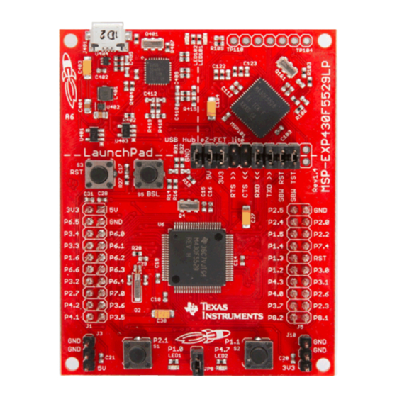
· 4 serial interfaces (SPI, UART, I C) · Analog comparator · Much more ! Figure 7. EVM Features and Controls SLAU533B – September 2013 – Revised June 2014 MSP-EXP430F5529LP LaunchPad™ Development Kit User's Guide Submit Documentation Feedback Copyright © 2013–2014, Texas Instruments Incorporated... -
Page 12: Block Diagram
Jumper Block USB BSL Reset Target Device MSP430F5529 32kHz 4MHz User LEDs and Switches Figure 8. Block Diagram MSP-EXP430F5529LP LaunchPad™ Development Kit User's Guide SLAU533B – September 2013 – Revised June 2014 Submit Documentation Feedback Copyright © 2013–2014, Texas Instruments Incorporated... -
Page 13: Hardware Features
P4.2/PM_UCB1SOMI/PM_UCB1SCL P4.1/PM_UCB1SIMO/PM_UCB1SDA P8.0 P4.0/PM_UCB1STE/PM_UCA1CLK P8.1 P8.2 P3.7/TB0OUTH/SVMOUT DVCC1 P3.6/TB0.6 DVSS1 P3.5/TB0.5 VCORE P3.4/UCA0RXD/UCA0SOMI Figure 9. MSP430F5529 Pinout SLAU533B – September 2013 – Revised June 2014 MSP-EXP430F5529LP LaunchPad™ Development Kit User's Guide Submit Documentation Feedback Copyright © 2013–2014, Texas Instruments Incorporated... -
Page 14: Ez-Fet Lite Emulator
F5529 device on the F5529 LaunchPad, you can disconnect the F5529 using the isolation jumper block and wire your hardware to the emulator through this block. MSP-EXP430F5529LP LaunchPad™ Development Kit User's Guide SLAU533B – September 2013 – Revised June 2014 Submit Documentation Feedback Copyright © 2013–2014, Texas Instruments Incorporated... -
Page 15: On-Board Usb Bus Path
USB Connector TUSB2046 Full-Speed USB Hub Target eZ-FET lite F5529 Emulator Figure 11. On-Board USB Bus Path SLAU533B – September 2013 – Revised June 2014 MSP-EXP430F5529LP LaunchPad™ Development Kit User's Guide Submit Documentation Feedback Copyright © 2013–2014, Texas Instruments Incorporated... -
Page 16: F5529 Launchpad Usb Interfaces
Jumpers Control Power Connection 5529 Target + BoosterPack 5V MSP430F5529 Target Device Figure 13. F5529 LaunchPad Power Supply MSP-EXP430F5529LP LaunchPad™ Development Kit User's Guide SLAU533B – September 2013 – Revised June 2014 Submit Documentation Feedback Copyright © 2013–2014, Texas Instruments Incorporated... - Page 17 UART. The backchannel UART (USCI_A1) is independent of the UART on the 40-pin BoosterPack connector (USCI_A0). SLAU533B – September 2013 – Revised June 2014 MSP-EXP430F5529LP LaunchPad™ Development Kit User's Guide Submit Documentation Feedback Copyright © 2013–2014, Texas Instruments Incorporated...
-
Page 18: Backchannel Uart Pathway
PC application configures the baudrate to be the same as what is configured on the USCI_A1. MSP-EXP430F5529LP LaunchPad™ Development Kit User's Guide SLAU533B – September 2013 – Revised June 2014 Submit Documentation Feedback Copyright © 2013–2014, Texas Instruments Incorporated... -
Page 19: Isolation Jumper Block
SBW TST Spy-Bi-Wire emulation: SBWTCK clock signal. This pin also functions as the TST signal. Not connected. Reserved. SLAU533B – September 2013 – Revised June 2014 MSP-EXP430F5529LP LaunchPad™ Development Kit User's Guide Submit Documentation Feedback Copyright © 2013–2014, Texas Instruments Incorporated... -
Page 20: Measure Msp430 Current Draw
5. Measure the current. (Keep in mind that if the current levels are fluctuating, it may be difficult to get a stable measurement. It is easier to measure quiescent states.) MSP-EXP430F5529LP LaunchPad™ Development Kit User's Guide SLAU533B – September 2013 – Revised June 2014 Submit Documentation Feedback Copyright © 2013–2014, Texas Instruments Incorporated... -
Page 21: Using An External Power Source
5529 Target + BoosterPack 5V MSP430F5529 Target Device Figure 17. Power Block Diagram for Default Configuration With USB Power Only SLAU533B – September 2013 – Revised June 2014 MSP-EXP430F5529LP LaunchPad™ Development Kit User's Guide Submit Documentation Feedback Copyright © 2013–2014, Texas Instruments Incorporated... -
Page 22: Power Block Diagram For External 3.3-V Power Source
USB module's VBUS and VUSB rails and the DVCC and AVCC rails used by the rest of the F5529. MSP-EXP430F5529LP LaunchPad™ Development Kit User's Guide SLAU533B – September 2013 – Revised June 2014 Submit Documentation Feedback Copyright © 2013–2014, Texas Instruments Incorporated... -
Page 23: Power Block Diagram For External 5-V Power Source Without Usb Connection
5529 Target + BoosterPack 5V MSP430F5529 Target Device Figure 19. Power Block Diagram for External 5-V Power Source Without USB Connection SLAU533B – September 2013 – Revised June 2014 MSP-EXP430F5529LP LaunchPad™ Development Kit User's Guide Submit Documentation Feedback Copyright © 2013–2014, Texas Instruments Incorporated... -
Page 24: Power Block Diagram For External 5-V Power Source With Usb Connection
5529 Target + BoosterPack 5V MSP430F5529 Target Device Figure 20. Power Block Diagram for External 5-V Power Source With USB Connection MSP-EXP430F5529LP LaunchPad™ Development Kit User's Guide SLAU533B – September 2013 – Revised June 2014 Submit Documentation Feedback Copyright © 2013–2014, Texas Instruments Incorporated... -
Page 25: Using The Ez-Fet Lite Emulator With A Different Target
The USB BSL button on the F5529 LaunchPad (see Figure 21) serves this purpose. Figure 21. USB BSL Button SLAU533B – September 2013 – Revised June 2014 MSP-EXP430F5529LP LaunchPad™ Development Kit User's Guide Submit Documentation Feedback Copyright © 2013–2014, Texas Instruments Incorporated... -
Page 26: Identifying The Usb Bsl's Hid Interface In Device Manager
If these interface entries do not appear, then something went wrong in the procedure to press the USB BSL button to invoke the BSL. Re-try the procedure. MSP-EXP430F5529LP LaunchPad™ Development Kit User's Guide SLAU533B – September 2013 – Revised June 2014 Submit Documentation Feedback Copyright © 2013–2014, Texas Instruments Incorporated... -
Page 27: Boosterpack Pinout
The F5529 function whose color matches the BoosterPack function shows the specific software-configurable function by which the F5529 LaunchPad adheres to the standard. SLAU533B – September 2013 – Revised June 2014 MSP-EXP430F5529LP LaunchPad™ Development Kit User's Guide Submit Documentation Feedback Copyright © 2013–2014, Texas Instruments Incorporated... -
Page 28: F5529 Launchpad To Boosterpack Connector Pinout
Pinout Standard F5529 LaunchPad Power Analog General I/O Unused function Figure 23. F5529 LaunchPad to BoosterPack Connector Pinout MSP-EXP430F5529LP LaunchPad™ Development Kit User's Guide SLAU533B – September 2013 – Revised June 2014 Submit Documentation Feedback Copyright © 2013–2014, Texas Instruments Incorporated... -
Page 29: Design Files
Rev 1.4 Initial release Removed TPS2041B power switches. Rev 1.5 Changed to sturdier BoosterPack male header pins SLAU533B – September 2013 – Revised June 2014 MSP-EXP430F5529LP LaunchPad™ Development Kit User's Guide Submit Documentation Feedback Copyright © 2013–2014, Texas Instruments Incorporated... -
Page 30: Software Examples
IAR KickStart, and IAR Embedded Workbench is fully supported. See the MSP430 software tools page to download these IDEs and for instructions on installation. MSP-EXP430F5529LP LaunchPad™ Development Kit User's Guide SLAU533B – September 2013 – Revised June 2014 Submit Documentation Feedback Copyright © 2013–2014, Texas Instruments Incorporated... -
Page 31: Browse To Demo Project For Import Function
25, and it has a checkmark to the left of it. Figure 25. When CCS Has Found the Project SLAU533B – September 2013 – Revised June 2014 MSP-EXP430F5529LP LaunchPad™ Development Kit User's Guide Submit Documentation Feedback Copyright © 2013–2014, Texas Instruments Incorporated... -
Page 32: Example Project Software Organization
The directory also contains the USB "event handlers". MSP-EXP430F5529LP LaunchPad™ Development Kit User's Guide SLAU533B – September 2013 – Revised June 2014 Submit Documentation Feedback Copyright © 2013–2014, Texas Instruments Incorporated... -
Page 33: Usb Configuration Files
*.dat input files for the Descriptor Tool are located inside each example's project directory. This allows easy regeneration of the output. SLAU533B – September 2013 – Revised June 2014 MSP-EXP430F5529LP LaunchPad™ Development Kit User's Guide Submit Documentation Feedback Copyright © 2013–2014, Texas Instruments Incorporated... -
Page 34: Out-Of-Box Experience: Emulstoragekeyboard
. Set USBHID_sendReport () to FALSE bUsbSendCompleted Figure 28. Demo Program Flow MSP-EXP430F5529LP LaunchPad™ Development Kit User's Guide SLAU533B – September 2013 – Revised June 2014 Submit Documentation Feedback Copyright © 2013–2014, Texas Instruments Incorporated... -
Page 35: Disable The Watchdog In Pre-Initialization
API the location of a RAM buffer that the application has allocated for the exchange of block data during READ and WRITE commands. SLAU533B – September 2013 – Revised June 2014 MSP-EXP430F5529LP LaunchPad™ Development Kit User's Guide Submit Documentation Feedback Copyright © 2013–2014, Texas Instruments Incorporated... - Page 36 READ or WRITE operation, and thus it is important to skip LPM0 and proceed to mscProcessBuffer(). MSP-EXP430F5529LP LaunchPad™ Development Kit User's Guide SLAU533B – September 2013 – Revised June 2014 Submit Documentation Feedback Copyright © 2013–2014, Texas Instruments Incorporated...
-
Page 37: Waking From Lpm0
Pushbutton is pressed bButton1Pressed bButton1Pressed flag is set to TRUE Wake from LPM Figure 30. Waking From LPM0 SLAU533B – September 2013 – Revised June 2014 MSP-EXP430F5529LP LaunchPad™ Development Kit User's Guide Submit Documentation Feedback Copyright © 2013–2014, Texas Instruments Incorporated... - Page 38 HID interface. It then sends specially formatted HID reports to the host, to tell it about key presses. While no key presses occur, no reports are sent. MSP-EXP430F5529LP LaunchPad™ Development Kit User's Guide SLAU533B – September 2013 – Revised June 2014 Submit Documentation Feedback Copyright © 2013–2014, Texas Instruments Incorporated...
- Page 39 LPM0 entry. This allows main() to send the next character, if one is waiting to be sent. SLAU533B – September 2013 – Revised June 2014 MSP-EXP430F5529LP LaunchPad™ Development Kit User's Guide Submit Documentation Feedback Copyright © 2013–2014, Texas Instruments Incorporated...
-
Page 40: Example: Simpleusbbackchannel
COM port on the host. Thus both sides of the communication loop terminate in virtual COM ports on the host. Through these COM ports, two instances of a terminal application can exchange data. MSP-EXP430F5529LP LaunchPad™ Development Kit User's Guide SLAU533B – September 2013 – Revised June 2014 Submit Documentation Feedback Copyright © 2013–2014, Texas Instruments Incorporated... -
Page 41: Movement Of Data In Simpleusbbackchannel: Cdc
To install the device, open Device Manager (see Section 3.7). Locate the device (see Figure 32). Right-click on it, and click Update Driver Software. SLAU533B – September 2013 – Revised June 2014 MSP-EXP430F5529LP LaunchPad™ Development Kit User's Guide Submit Documentation Feedback Copyright © 2013–2014, Texas Instruments Incorporated... -
Page 42: Simpleusbbackchannel's Usb Virtual Com Port, Needing A Driver
Linux PCs do not have this requirement. CDC interfaces enumerate silently as TTY devices in the \dev directory. MSP-EXP430F5529LP LaunchPad™ Development Kit User's Guide SLAU533B – September 2013 – Revised June 2014 Submit Documentation Feedback Copyright © 2013–2014, Texas Instruments Incorporated... -
Page 43: Device Manager
SMCLK is generally a good choice for the backchannel UART in a given application, but the clock speeds may change. Instructions for this are located in bcUart.h. SLAU533B – September 2013 – Revised June 2014 MSP-EXP430F5529LP LaunchPad™ Development Kit User's Guide Submit Documentation Feedback Copyright © 2013–2014, Texas Instruments Incorporated... -
Page 44: Backchannel Library: Constants To Configure
V levels result in higher quiescent current on the LDO. For this reason, V CORE CORE programmable. MSP-EXP430F5529LP LaunchPad™ Development Kit User's Guide SLAU533B – September 2013 – Revised June 2014 Submit Documentation Feedback Copyright © 2013–2014, Texas Instruments Incorporated... -
Page 45: Clock Settings
For a full explanation of the MSP430 clock system, see the Unified Clock System (UCS) chapter in the MSP430x5xx and MSP430x6xx Family User's Guide (SLAU208). SLAU533B – September 2013 – Revised June 2014 MSP-EXP430F5529LP LaunchPad™ Development Kit User's Guide Submit Documentation Feedback Copyright © 2013–2014, Texas Instruments Incorporated... - Page 46 Then, bcUartSend() sends them over the backchannel UART. MSP-EXP430F5529LP LaunchPad™ Development Kit User's Guide SLAU533B – September 2013 – Revised June 2014 Submit Documentation Feedback Copyright © 2013–2014, Texas Instruments Incorporated...
- Page 47 Instructions for using the Java HID Demo App are located in the Examples Guide PDF file in the MSP430 USB Developers Package. SLAU533B – September 2013 – Revised June 2014 MSP-EXP430F5529LP LaunchPad™ Development Kit User's Guide Submit Documentation Feedback Copyright © 2013–2014, Texas Instruments Incorporated...
-
Page 48: Starting Device Manager
To open Device Manager, click the Start button, click Run…, type "devmgmt.msc" in the Open field, and click OK (see Figure 35). Figure 35. Start Device Manager MSP-EXP430F5529LP LaunchPad™ Development Kit User's Guide SLAU533B – September 2013 – Revised June 2014 Submit Documentation Feedback Copyright © 2013–2014, Texas Instruments Incorporated... - Page 49 USB application. See this document for more information on using Device Manager. SLAU533B – September 2013 – Revised June 2014 MSP-EXP430F5529LP LaunchPad™ Development Kit User's Guide Submit Documentation Feedback Copyright © 2013–2014, Texas Instruments Incorporated...
-
Page 50: Additional Resources
Java HID Demo App, and a detailed programmer's guide to help you get started on writing your own USB applications. You can obtain the MSP430 USB Developers Package in these ways: MSP-EXP430F5529LP LaunchPad™ Development Kit User's Guide SLAU533B – September 2013 – Revised June 2014 Submit Documentation Feedback Copyright © 2013–2014, Texas Instruments Incorporated... -
Page 51: Msp430Ware And Ti Resource Explorer
MSP430Ware includes the TI Resource Explorer for easily browsing the tools. For example, Figure 38 shows all of the USB examples in the MSP430 USB Developers Package. SLAU533B – September 2013 – Revised June 2014 MSP-EXP430F5529LP LaunchPad™ Development Kit User's Guide Submit Documentation Feedback Copyright © 2013–2014, Texas Instruments Incorporated... -
Page 52: Usb Examples In The Usb Developers Package
USB project! MSP-EXP430F5529LP LaunchPad™ Development Kit User's Guide SLAU533B – September 2013 – Revised June 2014 Submit Documentation Feedback Copyright © 2013–2014, Texas Instruments Incorporated... -
Page 53: F5529 Code Examples
Search the forums at http://e2e.ti.com. If you cannot find your answer, post your question to the community. SLAU533B – September 2013 – Revised June 2014 MSP-EXP430F5529LP LaunchPad™ Development Kit User's Guide Submit Documentation Feedback Copyright © 2013–2014, Texas Instruments Incorporated... -
Page 54: Community At Large
A: The F5529 LaunchPad provides more functionality, and this requires it to use a device with more pins. Sockets for devices with this many pins are too expensive for the tool's target price. MSP-EXP430F5529LP LaunchPad™ Development Kit User's Guide SLAU533B – September 2013 – Revised June 2014 Submit Documentation Feedback Copyright © 2013–2014, Texas Instruments Incorporated... - Page 55 For those wishing the board to sit flat, holes are drilled in the corners so that standoffs can be fastened. Rubber bumper feet also should work. SLAU533B – September 2013 – Revised June 2014 MSP-EXP430F5529LP LaunchPad™ Development Kit User's Guide Submit Documentation Feedback Copyright © 2013–2014, Texas Instruments Incorporated...
-
Page 56: Schematics
Free IO pins: 4.6, 5.0, 5.1, 5.6, 5.7, 7.1, 7.2, 7.3, 7.5, 7.6, 7.7, 8.0, PJ.x (4) Figure 40. Schematics (1 of 4) MSP-EXP430F5529LP LaunchPad™ Development Kit User's Guide SLAU533B – September 2013 – Revised June 2014 Submit Documentation Feedback Copyright © 2013–2014, Texas Instruments Incorporated... -
Page 57: Schematics (2 Of 4)
STAND1 JP6.3 >> EZFET_UARTRTS P1.7 >> JP6.4 << EZFET_UARTCTS P6.7 << Figure 41. Schematics (2 of 4) SLAU533B – September 2013 – Revised June 2014 MSP-EXP430F5529LP LaunchPad™ Development Kit User's Guide Submit Documentation Feedback Copyright © 2013–2014, Texas Instruments Incorporated... -
Page 58: Schematics (3 Of 4)
EZFET_PU.1/DM HUB_DM2 EZFET_PU.0/DP HUB_DP2 R104 C110 C111 LED102 R106 LED101 green Figure 42. Schematics (3 of 4) MSP-EXP430F5529LP LaunchPad™ Development Kit User's Guide SLAU533B – September 2013 – Revised June 2014 Submit Documentation Feedback Copyright © 2013–2014, Texas Instruments Incorporated... - Page 59 HUB_DM1 HUB_DP1 R417 C411 C412 R418 R419 USB Hub and Power Figure 43. Schematics (4 of 4) SLAU533B – September 2013 – Revised June 2014 MSP-EXP430F5529LP LaunchPad™ Development Kit User's Guide Submit Documentation Feedback Copyright © 2013–2014, Texas Instruments Incorporated...
-
Page 60: Revision History
Removed FAQ that started "Q: Where can I find hardware design files for older.." NOTE: Page numbers for previous revisions may differ from page numbers in the current version. Revision History SLAU533B – September 2013 – Revised June 2014 Submit Documentation Feedback Copyright © 2013–2014, Texas Instruments Incorporated... - Page 61 IMPORTANT NOTICE Texas Instruments Incorporated and its subsidiaries (TI) reserve the right to make corrections, enhancements, improvements and other changes to its semiconductor products and services per JESD46, latest issue, and to discontinue any product or service per JESD48, latest issue.
Need help?
Do you have a question about the LaunchPad MSP-EXP430F5529LP and is the answer not in the manual?
Questions and answers