Table of Contents
Advertisement
Table of Contents
Receiving instructions:
After delivery, remove the packaging from the product. Inspect the product closely to determine
whether it sustained damage during transport. If damage is discovered, record a complete description
of it on the bill of lading. If the product is undamaged, discard the packaging.
NOTE:
The end-user is solely responsible for confirming that product design, use, and maintenance comply
with laws, regulations, codes, and mandatory standards applied where the product is used.
Replacement Parts and Technical Service:
For answers to questions not addressed in these instructions and to order replacement parts, labels,
and accessories, call our Technical Service and Parts Department at (260) 665-7586. The department
can also be contacted online at http://www.vestilmfg.com/parts_info.htm.
Specifications...............................................................................................................................................................
Words..................................................................................................................................................................
Hazards.........................................................................................................................................................................
Installation...................................................................................................................................................................
Dumper......................................................................................................................................................
Inspections..................................................................................................................................................................
Operation............................................................................................................................................... ...5,
Figs.
1, 2, & 3: Electric Circuit Diagrams ...............................................................................................7, 8, &
Fig. 4: Motor & Transformer Connection
Figs.
5A, 5B, &
Electrical Circuit Diagrams....................................................................................11, 12, &
Figs. 6A
&
6B:
Hydraulic Circuit Diagrams.......................................................................................................................
Figs.
7A, 7B, &
7C:
Exploded Parts Diagrams.....................................................................................15, 16, &
HBD-GATE.......................................................................................................................
Troubleshooting.......................................................................................................................................
Limited
Warranty..........................................................................................................................................................
Diagram........................................................................................................................................................
Table of Contents
2999 North Wayne Street, P.O. Box 507, Angola, IN 46703
Telephone: (260) 665-7586 -or- Toll Free (800) 348-0868
Web: www.vestilmfg.com
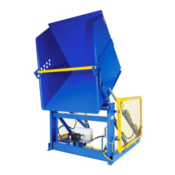
HBD-Series Hydraulic Box Dumpers
Instruction Manual
Table of Contents
Diagrams............................................................................................
Copyright 2019 Vestil Manufacturing Co.
5/3/2019
Vestil Manufacturing Corp.
Fax: (260) 665-1339
HBD MANUAL
Email: info@vestil.com
Page 1 of 21
2
3
3
4
4
5
6
9
10
13
14
17
18
19
20
21
Advertisement
Table of Contents

Related Manuals for Vestil HBD Series


Summary of Contents for Vestil HBD Series
-
Page 1: Table Of Contents
Electrical Circuit Diagrams……………………………………………………………………...…11, 12, & Figs. 6A & Hydraulic Circuit Diagrams………......................Figs. 7A, 7B, & Exploded Parts Diagrams…………………………………………………...…………………….15, 16, & Installing Option HBD-GATE……………………..………………………………………………………………………………… Troubleshooting……...……………………………………………………………………………………………………………… Limited Warranty……………..…………….......................... Labeling Diagram……………….……………........................Table of Contents Copyright 2019 Vestil Manufacturing Co. Page 1 of 21... -
Page 2: Specifications
60” ” 52” x 50” ” 69” 6,000 lb. 2021 lb. HBD-6-60 196 cm 152 cm 380 cm (132 x 127)cm 174 cm 176 cm 2727 kg 919kg Table of Contents Copyright 2019 Vestil Manufacturing Co. Page 2 of 21... -
Page 3: Signal Words
• DO NOT modify the box dumper in any way without first obtaining written approval from Vestil. Unauthorized modifications might make the dumper unsafe to use, and could result in operator and/or bystander injury. -
Page 4: Installation
The instructions that appear below are recommendations about essential, minimum steps necessary for safe installation. If law enforced where the dumper is used requires you to depart from these directions, Vestil is not responsible for any consequential damages sustained as a result of the installation. Installation requires at least: •... -
Page 5: Inspections
• Lowering solenoid valve: electrically-operated cartridge valve with an integral screen to keep contaminants from entering the valve. • Counterbalance valves (6,000lb. rated load models only): allow smooth motion in double-acting hydraulic circuits. Table of Contents Copyright 2019 Vestil Manufacturing Co. Page 5 of 21... - Page 6 4. Check the oil level in the reservoir. If the surface of the oil is lower than 1 to 1½ in. below the fill hole, add oil until it is between 1 and 1½ inches of the fill hole. Table of Contents Copyright 2019 Vestil Manufacturing Co. Page 6 of 21...
-
Page 7: Figs
NOTE: In this diagram, all components are represented with the chute in “home” location, i.e. resting, lowered position. NOTE: Overcurrent and short- circuit protection should be provided by the end user in accordance with recommendations and requirements in NEC (NFPA 70) and local codes. Table of Contents Copyright 2019 Vestil Manufacturing Co. Page 7 of 21... -
Page 8: Figs
NOTE: Overcurrent and short- circuit protection should be provided by the end user in accordance with recommendations and requirements in NEC (NFPA 70) and local codes. Table of Contents Copyright 2019 Vestil Manufacturing Co. Page 8 of 21... - Page 9 NOTE: Overcurrent and short-circuit protection should be provided by the end user in accordance with recommendations and requirements in NEC (NFPA 70) and local codes. Table of Contents Copyright 2019 Vestil Manufacturing Co. Page 9 of 21...
-
Page 10: Diagrams
Attach thermostat leads to: 1) Grounded side of the transformer secondary; and 2) Motor relay coil. It does not matter which lead attaches to each location. Transformer wiring diagram: Table of Contents Copyright 2019 Vestil Manufacturing Co. Page 10 of 21... - Page 11 NEC (NFPA 70) and local codes. NOTE 2: In this diagram, all components are represented with the chute in “home” location, i.e. fully lowered position. Table of Contents Copyright 2019 Vestil Manufacturing Co. Page 11 of 21...
-
Page 12: Electrical Circuit Diagrams
NEC (NFPA 70) and local codes. NOTE 2: In this diagram, all components are represented with the chute in “home” location, i.e. resting, lowered position. Table of Contents Copyright 2019 Vestil Manufacturing Co. Page 12 of 21... - Page 13 NEC (NFPA 70) and local codes. NOTE 2: In this diagram, all components are represented with the chute in “home” location, i.e. resting, lowered position. Table of Contents Copyright 2019 Vestil Manufacturing Co. Page 13 of 21...
- Page 14 Table of Contents 5/3/2019 HBD MANUAL FIG. 6A: 2,000lb. & 4,000lb. capacity models, hydraulic circuit diagram FIG. 6B: Double acting (6,000lb. capacity models) hydraulic circuit diagram TO PUMP FROM PUMP Table of Contents Copyright 2019 Vestil Manufacturing Co. Page 14 of 21...
- Page 15 – 16 x 1in. HHCS #2 zinc-plated bolt 33008 in. USS zinc-plated flat washer 37024 in. Nylock insert nut 09-516-012 Mounting block subassembly bracket 13363 ”-10 x 2 HHCS #5 zinc-plated bolt Table of Contents Copyright 2019 Vestil Manufacturing Co. Page 15 of 21...
- Page 16 Nylon insert lock nut, gr. 2, zinc finish, ”-16 09-516-012 Subassembly, bracket, mounting block 13363 ”-10 x 2” HHCS, #5, zinc plated bolt 09-021-952 Cylinder, hydraulic, 3” x 18”, ram style Table of Contents Copyright 2019 Vestil Manufacturing Co. Page 16 of 21...
- Page 17 Hex bolt, gr. A, zinc plated, ”-16 x 1” 11105 Nylon insert lock nut, gr. 2, zinc finish, ”-16 37024 ”-10 x 2 ” HHHCS #5 zinc plated bolt 13363 Table of Contents Copyright 2019 Vestil Manufacturing Co. Page 17 of 21...
-
Page 18: Installing Option
Anchor the door assembly to the ground by installing ” anchor bolts of appropriate length through the 2 bolt holes in each foot. Bolt & flat Flat washer & washer lock nut Install ” anchor bolts Table of Contents Copyright 2019 Vestil Manufacturing Co. Page 18 of 21... -
Page 19: Troubleshooting
Flow control spool is stuck. b. Same as 5a. 7. Spongy or jerky chute motion. 7. Air in the hydraulic cylinders. Bleed air per procedure described on p. 6 of this manual. Table of Contents Copyright 2019 Vestil Manufacturing Co. Page 19 of 21... - Page 20 Warrantee (you) for warranty service. Who may request service? Only a warrantee may request service. You are a warrantee if you purchased the product from Vestil or from an authorized distributor AND Vestil has been fully paid.
-
Page 21: Labeling Diagram
B: Label #287 C: Label #250 D: Label #221 (alternating C & D corners) E: Label #204 F: Label #206 G: Label #208 (on both left and right sides) Table of Contents Copyright 2019 Vestil Manufacturing Co. Page 21 of 21...
Need help?
Do you have a question about the HBD Series and is the answer not in the manual?
Questions and answers