Advertisement
Quick Links
HBD-S
Receiving instructions:
After delivery, Immediately remove the packaging from the product in a manner that preserves the packaging
and maintains the orientation of the product in the packaging; then inspect the product closely to determine
whether it sustained damage during transport. If damage is discovered during the inspection, immediately
record a complete description of the damage on the bill of lading. If the product is undamaged, discard
the packaging.
NOTES:
1) Compliance with laws, regulations, codes, and non-voluntary standards enforced in the location where the
product is used is exclusively the responsibility of the owner/end-user.
2) Vestil is not liable for any injury or property damage that occurs as a consequence of failing to apply either:
a) Instructions in this manual; or b) information provided on labels affixed to the product. Neither is Vestil
responsible for any consequential damages sustained as a result of failing to exercise sound judgment while
assembling, installing, using or maintaining this product.
Table of Contents
Product Introduction.............................. 2
Hazard identification................................ 3
Safety Guidelines.................................... 3
Installation instructions........................... 4
Operation instructions............................ 4
Inspections.......................................... 5
Power unit operation.............................. 5 - 6
Parts lists............................................ 12
Troubleshooting guide............................ 18
Limited warranty................................... 19
Copyright 2016 Vestil Manufacturing Co.
Rev.04/2016
2999 North Wayne Street, P.O. Box 507, Angola, IN 46703
Telephone: (260) 665-7586 -or- Toll Free (800) 348-0868
Url: www.vestilmfg.com
H
ERIES
YDRAULIC
I
NSTRUCTION
Table of Figures
Fig. 1 Installation diagram..................................... 4
Fig. 2 Limit switch effect on dump angle................... 5
Fig. 3A-3C Electrical circuit diagrams ..................... 7 - 9
Fig. 4 Motor & transformer connection diagrams....... 10
Fig. 5A-5C Electrical circuit diagrams...................... 11 - 13
Fig. 6A Hydraulic circuit diagram (2k & 4k)................ 14
Fig. 6B Hydraulic system diagram (6k).................... 14
Figs. 7A-7C Exploded parts diagrams..................... 15 - 17
Fig. 8 "Product markings & labels"......................... 20
Vestil Manufacturing Corp.
Fax: (260) 665-1339
Email: sales@vestil.com
B
D
OX
M
ANUAL
HBD, MANUAL.doc
UMPERS
1 of 20
Advertisement

Related Manuals for Vestil HBD Series


Summary of Contents for Vestil HBD Series
-
Page 1: Table Of Contents
2) Vestil is not liable for any injury or property damage that occurs as a consequence of failing to apply either: a) Instructions in this manual; or b) information provided on labels affixed to the product. Neither is Vestil responsible for any consequential damages sustained as a result of failing to exercise sound judgment while assembling, installing, using or maintaining this product. -
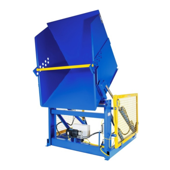
Page 2: Product Introduction
RODUCT NTRODUCTION Thank you for purchasing a hydraulic box dumper (“box dumper”, “dumper” or “HBD”) made by Vestil Manufacturing Corporation (“Vestil”). Our dumpers are durable, high-quality products that are rigorously engineered to provide safety- enhancing features while preserving simplicity. Although use and maintenance procedures are relatively intuitive, any person who might use or maintain this product must familiarize him/herself with the instructions provided in this manual. - Page 3 DO NOT modify the box dumper in any way UNLESS you first obtain express, written approval from Vestil. Unauthorized modifications might make the dumper unsafe to use, and could result in operator and/or bystander injury.
-
Page 4: Installation Instructions
The instructions that appear below are recommendations about essential, minimum steps necessary for safe installation. If law enforced where the dumper is used requires you to depart from these directions, Vestil is not responsible for any consequential damages sustained as a result of the installation. Installation requires at least: ... -
Page 5: Inspections
Hydraulic cylinders: 2,00lb. and 4,00lb. rated load models utilize displacement style cylinders. Each cylinder includes a bleeder valve (located at top end) for removing air from the hydraulic system. 6,000lb. HBD models use double action cylinders. Copyright 2016 Vestil Manufacturing Co. 5 of 20... - Page 6 Check the oil level in the reservoir. If the surface of the oil is lower than 1 to 1½ in. below the fill hole, add oil until it is between 1 and 1½ inches of the fill hole. Copyright 2016 Vestil Manufacturing Co. 6 of 20...
- Page 7 NOTE: In this diagram, all components are represented with the chute in “home” location, i.e. resting, lowered position. NOTE: Overcurrent and short- circuit protection should Control relay base layout be provided by the end user in accordance with recommendations and requirements in NEC (NFPA 70) and local codes. Copyright 2016 Vestil Manufacturing Co. 7 of 20...
- Page 8 11.6-10.2 FLA, 3450RPM Control relay base layout NOTE: Overcurrent and short- circuit protection should be provided by the end user in accordance with recommendations and requirements in NEC (NFPA 70) and local codes. Copyright 2016 Vestil Manufacturing Co. 8 of 20...
- Page 9 5.6/2.8 FLA, 3450RPM Control relay base layout NOTE: Overcurrent and short-circuit protection should be provided by the end user in accordance with recommendations and requirements in NEC (NFPA 70) and local codes. Copyright 2016 Vestil Manufacturing Co. 9 of 20...
- Page 10 2HP, 5.5HP, and 6.5HP three phase motors Attach thermostat leads to: 1) Grounded side of the transformer secondary; and 2) Motor relay coil. It does not matter which lead attaches to each location. Transformer wiring diagram: Copyright 2016 Vestil Manufacturing Co. 10 of 20...
- Page 11 NEC (NFPA 70) and local codes. NOTE 2: In this diagram, all components are represented with the chute in “home” location, i.e. resting, lowered position. Copyright 2016 Vestil Manufacturing Co. 11 of 20...
- Page 12 NEC (NFPA 70) and local codes. NOTE 2: In this diagram, all components are represented with the chute in “home” location, i.e. resting, lowered position. Copyright 2016 Vestil Manufacturing Co. 12 of 20...
- Page 13 NEC (NFPA 70) and local codes. NOTE 2: In this diagram, all components are represented with the chute in “home” location, i.e. resting, lowered position. Copyright 2016 Vestil Manufacturing Co. 13 of 20...
- Page 14 Rev. 04/2016 HBD, MANUAL.doc FIG. 6A: 2,000lb. & 4,000lb. capacity models, hydraulic circuit diagram FIG. 6B: 6,000lb. capacity models, hydraulic circuit diagram TO PUMP FROM PUMP Copyright 2016 Vestil Manufacturing Co. 14 of 20...
- Page 15 Chute weldment: HBD-2-36 34-545-004 HBD-2-48 HCD-2-60 11105 in. – 16 x 1in. HHCS #2 zinc-plated bolt 33008 in. USS zinc-plated flat washer 37024 in. Nylock insert nut 09-516-012 Mounting block subassembly bracket Copyright 2016 Vestil Manufacturing Co. 15 of 20...
- Page 16 Chute weldment: 34-545-004 HBD-4-36 34-545-005 HBD-4-48 34-545-006 HBD-4-60 33008 in. USS zinc-plated flat washer 11105 in. – 16 x 1in #2 zinc-plated bolt 37024 in. Nylock insert nut 09-516-012 Block subassembly bracket Copyright 2016 Vestil Manufacturing Co. 16 of 20...
- Page 17 Chute weldment: 34-545-019 HBD-6-36 34-545-020 HBD-6-48 34-545-018 HBD-6-60 09-516-012 Mounting block bracket subassembly 33008 in. USS zinc-plated flat washer 11105 in. – 16 x 1in #2 zinc-plated bolt in. Nylock insert nut 37024 Copyright 2016 Vestil Manufacturing Co. 17 of 20...
-
Page 18: Troubleshooting Guide
6a. Same as 3e. b. Flow control spool is stuck. b. Same as 5a. 7. Spongy or jerky chute motion. 7. Air in the hydraulic cylinders. 7. Bleed air per procedure described in this manual. Copyright 2016 Vestil Manufacturing Co. 18 of 20... -
Page 19: Limited Warranty
(you) for warranty service. Who may request service? Only a warrantee may request service. You are a warrantee if you purchased the product from Vestil or from an authorized distributor AND Vestil has been fully paid. - Page 20 A: Label #220 B: Label #287 C: Label #250 C & D (alternating corners) D: Label #221 E: Label #204 F: Label #206 G: Label #208 (on both left and right sides) Copyright 2016 Vestil Manufacturing Co. 20 of 20...
Need help?
Do you have a question about the HBD Series and is the answer not in the manual?
Questions and answers