Table of Contents
Advertisement
Quick Links
Rev. 9/25/2017
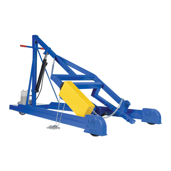
HDC-450 Series Manually-Propelled Hydraulic Drum Carriers Instruction Manual
Receiving instructions:
After delivery, remove the packaging from the product. Inspect the product closely to determine whether it
sustained damage during transport. If damage is discovered, immediately record a complete description of the
damage on the bill of lading. If the product is undamaged, discard the packaging.
Note:
The end-user is solely responsible for confirming that product design complies with all laws, regulations, codes,
and mandatory standards applied where the product is used.
Signal Words....................................................................................................................................... 2
Hazards of Improper Use................................................................................................................. 2
Specifications (Dimensions, Net Weight, Capacity)............................................................................... 3
HDC-450-60 Exploded Parts Diagram and Bill of Materials...................................................................... 4 - 5
HDC-450-72 Exploded Parts Diagram and Bill of Materials..................................................................... 5 - 6
HDC-450-84 Exploded Parts Diagram and Bill of Materials...................................................................... 7 - 8
HDC-450-96 Exploded Parts Diagram and Bill of Materials..................................................................... 8 - 9
Hydraulic System - Foot Pump (Standard Units): Operation; Purging Air from the Pump;
Purging Air from the Cylinder........................................................................................................... 10
"Autoshifter" Foot Pump Exploded Parts Diagram and Bill of Materials...................................................... 11 - 12
Hydraulic System Inspections and Maintenance.................................................................................. 12 - 13
Troubleshooting (foot pump)............................................................................................................ 13
Electrically Powered Drum Carriers (Options HDC-DC and HDC-AC)....................................................... 14
DC Modular Power Unit Exploded Parts Diagram and Bill of Materials...................................................... 14
DC Manifold Assembly Exploded Parts Diagram (Item 24 on p. 14).......................................................... 15
12VDC Modular Power Unit Electrical Circuit Diagram.......................................................................... 15
12VDC Modular Power Unit Layout................................................................................................... 16
AC Modular Power Unit Exploded Parts Diagram and Bill of Materials...................................................... 17
Electrical Box and Manifold Exploded Parts Diagrams (Items 2 and 12 on p. 17)........................................ 18
115VAC Modular Power Unit Electrical Circuit Diagram......................................................................... 18
115VAC Modular Power Unit Layout................................................................................................. 19
Hydraulic Circuit Diagram (Powered Units; 01-127-010 Rev. C)............................................................... 19
Operating the Modular Power Unit (Raising & Lowering the Pivot Arm)..................................................... 20
Using the Battery Charger (HDC-DC Units Only).................................................................................. 21
Lifting drums (standard and powered units)......................................................................................... 22
Inspections & Maintenance..................................................................................................................... 23
Troubleshooting guide (HDC-DC & HDC-AC)...................................................................................... 24 - 25
Labeling diagram........................................................................................................................... 25
Limited warranty............................................................................................................................ 26
Copyright 2017 Vestil Manufacturing Corp.
Vestil Manufacturing Corp.
2999 North Wayne Street, P.O. Box 507, Angola, IN 46703
Telephone: (260) 665-7586 -or- Toll Free (800) 348-0868
Fax: (260) 665-1339
Web:
www.vestilmfg.com
Table of Contents
HDC-450, MANUAL
e-mail:
info@vestil.com
*Unit shown is an HDC-450-60
Page 1 of 26
Advertisement
Table of Contents
Troubleshooting

Related Manuals for Vestil HDC-450 Series


Summary of Contents for Vestil HDC-450 Series
-
Page 1: Table Of Contents
Web: www.vestilmfg.com e-mail: info@vestil.com HDC-450 Series Manually-Propelled Hydraulic Drum Carriers Instruction Manual *Unit shown is an HDC-450-60 Receiving instructions: After delivery, remove the packaging from the product. Inspect the product closely to determine whether it sustained damage during transport. If damage is discovered, immediately record a complete description of the damage on the bill of lading. -
Page 2: Signal Words
DO NOT modify the product in any way UNLESS you first obtain written approval from Vestil. Unapproved modifications might make the lift unsafe to use and automatically void the Limited Warranty (see p. 26). -
Page 3: Specifications (Dimensions, Net Weight, Capacity)
743 lb. ” ” ” ” ” ” 96” ” 450-96 364 kg 338 kg **NOTE: For all models, capacity is reduced to 500 pounds whenever a drum is half-full or less. Copyright 2017 Vestil Manufacturing Corp. Page 3 of 26... -
Page 4: Hdc-450-60 Exploded Parts Diagram And Bill Of Materials
Rev. 9/25/2017 HDC-450, MANUAL HDC-450-60 Exploded Parts Diagram (Bill of Materials on p. 5) Copyright 2017 Vestil Manufacturing Corp. Page 4 of 26... - Page 5 16-132-216 Caster, wheel, GFN-8/2-W finish, ”-16 Hex bolt, gr. A, zinc finish, ”-16 x 09-516-004- Subassembly, gear train, pull 11129 48” chain 36106 Hex nut, gr. A, zinc plated, ”-16 15-023-001 Reservoir Copyright 2017 Vestil Manufacturing Corp. Page 5 of 26...
-
Page 6: Hdc-450-72 Exploded Parts Diagram And Bill Of Materials
Rev. 9/25/2017 HDC-450, MANUAL HDC-450-72 Exploded Parts Diagram (Bill of Materials on p. 5) Copyright 2017 Vestil Manufacturing Corp. Page 6 of 26... -
Page 7: Hdc-450-84 Exploded Parts Diagram And Bill Of Materials
Rev. 9/25/2017 HDC-450, MANUAL HDC-450-84 Exploded Parts Diagram (Bill of Materials on p. 8) Copyright 2017 Vestil Manufacturing Corp. Page 7 of 26... - Page 8 Caster, swivel, PU-5/2-S medium zinc finish, ” Nylon insert lock nut, gr. 2, zinc finish, 37024 13-025-023 Handle, grip, 1 ” I.D., red ”-16 09-112-029 Pin, clevis 16-132-216 Caster, wheel, GFN-8/2-W 15-023-001 Reservoir Copyright 2017 Vestil Manufacturing Corp. Page 8 of 26...
-
Page 9: Hdc-450-96 Exploded Parts Diagram And Bill Of Materials
Rev. 9/25/2017 HDC-450, MANUAL HDC-450-96 Exploded Parts Diagram (Bill of Materials on p. 8) Copyright 2017 Vestil Manufacturing Corp. Page 9 of 26... -
Page 10: Purging Air From The Cylinder
4. Repeat step 3 until air is completely removed from the cylinder (i.e. only oil flows from the bleeder screw). 5. Check all of the hydraulic lines for oil leaks. 6. Return the unit to service. Copyright 2017 Vestil Manufacturing Corp. Page 10 of 26... -
Page 11: Autoshifter" Foot Pump Exploded Parts Diagram And Bill Of Materials
” 70D NBR applications. unused pressure OR-904-N70 O-ring, #4 SAE port intake/return ports are each plugged with an OR-906-N70 O-ring, #6 SAE port SAE #6 port plug. 01-111-013 Bearing, self-lubricating, ” x ” Copyright 2017 Vestil Manufacturing Corp. Page 11 of 26... -
Page 12: Hydraulic System Inspections And Maintenance
(A) Before Each Use Check For Any of the Following Conditions. Do not return the unit to service unless it is in normal operating condition. Oil leaks from the pump, hoses, hose fittings, etc. Pinched or chafed hoses Copyright 2017 Vestil Manufacturing Corp. Page 12 of 26... -
Page 13: Troubleshooting (Foot Pump)
Remove valve and inspect for debris or moving freely non-operating spool 10. Pivot arm rises part way r. Air trapped in small pump chamber r. Perform “Purging air from the pump” on p. and then stops Copyright 2017 Vestil Manufacturing Corp. Page 13 of 26... -
Page 14: Electrically Powered Drum Carriers (Options Hdc-Dc And Hdc-Ac)
– 20 x 1in. TPHMS 29185 zinc-plated 23255 SHCS utility grade 33687 High collar lock washer 152400-03 Molded cord Connector, charge 150CCTM.OEM 3MT ST3540 1in. hook and loop press 10” Copyright 2017 Vestil Manufacturing Corp. Page 14 of 26... -
Page 15: Dc Manifold Assembly Exploded Parts Diagram (Item
99-153-011 Valve, check 12VDC modular power unit electrical circuit diagram NOTE: Overcurrent & short-circuit protection as well as system disconnect must be provided. Limit switch or jumper wire used where applicable. Copyright 2017 Vestil Manufacturing Corp. Page 15 of 26... -
Page 16: 12Vdc Modular Power Unit Layout
Rev. 9/25/2017 HDC-450, MANUAL 12VDC modular power unit layout (part 1 of 2) 12VDC modular power unit layout (part 2 of 2) Copyright 2017 Vestil Manufacturing Corp. Page 16 of 26... -
Page 17: Ac Modular Power Unit Exploded Parts Diagram And Bill Of Materials
– 20 x 1in. TPHMS zinc- 29185 plated 23255 SHCS utility grade 33687 High collar lock washer 152400-03 Molded cord Connector, charge 150CCTM.OEM 3MT ST3540 1in. hook and loop press 10” Copyright 2017 Vestil Manufacturing Corp. Page 17 of 26... -
Page 18: Electrical Box And Manifold Exploded Parts Diagrams (Items 2 And
Flow control, 1.0GPM 115VAC modular power unit electrical circuit diagram NOTE: Overcurrent & short-circuit protection as well as system disconnect must be provided. Limit switch or jumper wire used where applicable. Copyright 2017 Vestil Manufacturing Corp. Page 18 of 26... -
Page 19: 115Vac Modular Power Unit Layout
Rev. 9/25/2017 HDC-450, MANUAL 115VAC modular power unit layout Hydraulic circuit diagram (Powered units; 01-127-010 Rev. C): Cylinder Copyright 2017 Vestil Manufacturing Corp. Page 19 of 26... -
Page 20: Operating The Modular Power Unit (Raising & Lowering The Pivot Arm)
Jog the motor to push air out of the system. 3. Only clear hydraulic fluid will flow from the bleeder screw opening when air has been completely removed. At that point, reinstall the bleeder screw. Copyright 2017 Vestil Manufacturing Corp. Page 20 of 26... -
Page 21: Using The Battery Charger (Hdc-Dc Units Only)
3) Examine the fuse (see diagrams on pages 13-14 (DC-powered) or 16-17(AC-powered)). Replace only with a fuse having the same rating as the original fuse. 4) It will take time before current begins to flow through a highly sulfated battery. Copyright 2017 Vestil Manufacturing Corp. Page 21 of 26... -
Page 22: Lifting Drums (Standard And Powered Units)
6. Rotate the drum to the upright position and return it to the ground (press the release lever or the white button on the handheld controller). Once the drum rests on the ground, press down on the clamp release (see step 3 above) and rotate the handle counterclockwise to release the chain. Copyright 2017 Vestil Manufacturing Corp. Page 22 of 26... -
Page 23: Inspections & Maintenance
Keep the product clean & dry. Lubricate moving parts at least once per month. o If repairs are necessary, only install manufacturer-approved replacement parts. Vestil is not responsible for problems or malfunctions that result from the use of unapproved replacement parts. -
Page 24: Troubleshooting Guide (Hdc-Dc & Hdc-Ac)
DO NOT remove the solenoid valve from the block because carriage will descend dangerously quickly.) gg. Faulty lowering solenoid coil. Remove and replace. DO NOT remove the Copyright 2017 Vestil Manufacturing Corp. Page 24 of 26... -
Page 25: Labeling Diagram
D: label 206 is applied to metal frame inside MPU cover D: label 206 is applied to metal frame inside MPU cover Label 295 (on MPU cover) Label 248; 249; 250; or 251 electrical system specifications Copyright 2017 Vestil Manufacturing Corp. Page 25 of 26... -
Page 26: Limited Warranty
The warranty period for original dynamic components is 90 days. For wearing parts, the warranty period is 90 days. The warranty periods begin on the date when Vestil ships the product to the warrantee. If the product was purchased from an authorized distributor, the periods begin when the distributor ships the product.
Need help?
Do you have a question about the HDC-450 Series and is the answer not in the manual?
Questions and answers