Table of Contents
Advertisement
03/10/03
Receiving instructions:
After delivery, remove the packaging from the product. Inspect the product closely to determine whether it
sustained damage during transport. If damage is discovered, record a complete description of it on the bill of
lading. If the product is undamaged, discard the packaging.
NOTE:
The end-user is solely responsible for confirming that product design, installation, use, and maintenance
comply with laws, regulations, codes, and mandatory standards applied where the product is used.
Table of Contents
Product Specifications................................... 2-3
Signal Words................................................. 4
Safe Use Recommendations............................ 4
Installation Instructions................................. 11
Loading the Dumper.................................... 11
Inspections................................................ 11-12
Power unit operation..................................... 12-13
Troubleshooting guide................................. 23
Labeling Diagram........................................ 24
Limited warranty......................................... 25
Copyright 2017 Vestil Manufacturing Co.
9/7/2017
2999 North Wayne Street, P.O. Box 507, Angola, IN 46703
Telephone: (260) 665-7586 -or- Toll Free (800) 348-0868
Web:
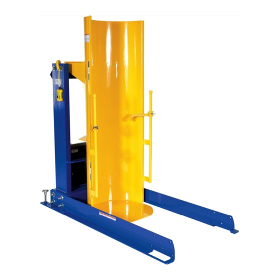
HDD-Series Hydraulic Drum Dumpers
Instruction Manual
Vestil Manufacturing Corp.
Fax: (260) 665-1339
www.vestilmfg.com
FIG. 1: HDD-36-S exploded parts diagram.................... 5
FIG. 2: HDD-48-S exploded parts diagram.................... 5
FIG. 3: HDD-60-S exploded parts diagram.................... 6
FIG. 4: HDD-72-S exploded parts diagram.................... 6
FIG. 5: HDD-36-P exploded parts diagram..................... 7
FIG. 6: HDD-48-P exploded parts diagram..................... 8
FIG. 7: HDD-60-P exploded parts diagram..................... 9
FIG. 8: HDD-72-S exploded parts diagram.................... . 10
FIG. 9: Hydraulic Circuit Diagram................................ . 13
FIGS. 10A-10F: Electrical Circuit Diagrams.................... 14-19
FIGS. 12A-12B: Modular Power Unit parts diagram........ . 21-22
HDD, MANUAL
e-mail:
info@vestil.com
1 of 25
Advertisement
Table of Contents

Subscribe to Our Youtube Channel
Related Manuals for Vestil HDD Series


Summary of Contents for Vestil HDD Series
-
Page 1: Table Of Contents
FIG. 9: Hydraulic Circuit Diagram………………………..13 Limited warranty………………………………….. 25 FIGS. 10A-10F: Electrical Circuit Diagrams……………….. 14-19 FIG. 11: Motor Lead Diagrams & Transformer diagram…. 20 FIGS. 12A-12B: Modular Power Unit parts diagram…….. . 21-22 Copyright 2017 Vestil Manufacturing Co. 1 of 25... -
Page 2: Product Specifications
72” ” ” ” ” 92” 750 lb. 1,113 lb. HDD-72-10-S 72” ” ” ” ” 92” 1,000 lb. 1,055 lb. HDD-72-15-S 72” ” ” ” ” 92” 1,500 lb. 1,036 lb. Copyright 2017 Vestil Manufacturing Co. 2 of 25... - Page 3 72” ” ” 96” ” 92” 750 lb. 1,034 lb. HDD-72-10-P 72” ” ” 96” ” 92” 1,000 lb. 1,100 lb. HDD-72-15-P 72” ” ” 96” ” 92” 1,500 lb. 1,115 lb. Copyright 2017 Vestil Manufacturing Co. 3 of 25...
-
Page 4: Signal Words
DO NOT modify the dumper in any way UNLESS you first obtain written approval from Vestil. Modifying the dumper without first receiving approval automatically voids the limited warranty and might make the dumper unsafe to use. -
Page 5: Table Of Figures Fig. 1: Hdd-36-S Exploded Parts Diagram
” - 20 shaft 22805 Elevator bolt, limit switch 11 09-545-030 Weldment, subassembly, chute 13365 ” – 10 UNC x 3” zinc- plated #5 bolt 13 99-158-008 Modular power unit w/out push buttons Copyright 2017 Vestil Manufacturing Co. 5 of 25... -
Page 6: Fig. 3: Hdd-60-S Exploded Parts Diagram
Pivot chute shaft Hydraulic cylinder: 99-021-909-001 ” x 18” 09-021-018 3” x 18” (HDD-72-15-S) 13365 ” – 10 UNC x 3” zinc- plated #5 bolt 99-158-008 Modular power unit w/out push buttons Copyright 2017 Vestil Manufacturing Co. 6 of 25... -
Page 7: Fig. 5: Hdd-36-P Exploded Parts Diagram
09-016-169 Bracket, wheel 09-545-028 Weldment, subassembly, chute 11219 ”–13 x 4” hex head bolt 08-025-008 4-handle bolt, 4” 16-111-003 Sleeve bearing for 2” wheel 37030 ” – 13 nylon insert lock nut Copyright 2017 Vestil Manufacturing Co. 7 of 25... -
Page 8: Fig. 6: Hdd-48-P Exploded Parts Diagram
08-025-008 4-handle bolt, 4” 09-514-131 Weldment, frame, stationary 37030 ” – 13 nylon insert lock nut 99-612-001 ”–16 x 5” bolt and nut combo. 33012 ” flat washer, low carbon, zinc finish Copyright 2017 Vestil Manufacturing Co. 8 of 25... -
Page 9: Fig. 7: Hdd-60-P Exploded Parts Diagram
08-025-008 4-handle bolt, 4” 09-514-127 Weldment, frame, stationary 37030 ” – 13 nylon insert lock nut 99-612-001 ”–16 x 5” bolt and nut combo. 33012 ” flat washer, low carbon, zinc finish Copyright 2017 Vestil Manufacturing Co. 9 of 25... -
Page 10: Fig. 8: Hdd-72-S Exploded Parts Diagram
11219 ”–13 x 4” hex head bolt Hydraulic cylinder: 99-021-909- ” x 18” 09-514-125 Weldment, frame, stationary 09-021-018 3” x 18” (HDD-72-15-P) 13365 ” – 10 x 3” HHCS #5 plain bolt Copyright 2017 Vestil Manufacturing Co. 10 of 25... -
Page 11: Installation Instructions
Listen for unusual sounds that might indicate binding or grinding during operation and watch for unusual movement. If you observe any unusual sound or movement, do not use the Modular power unit Copyright 2017 Vestil Manufacturing Co. 11 of 25... -
Page 12: Power Unit Operation
Releasing the DOWN button during operation causes all chute movement to stop. The chute will remain in the same position until you press either button on the pendant controller. Copyright 2017 Vestil Manufacturing Co. 12 of 25... -
Page 13: Fig. 9: Hydraulic Circuit Diagram
99-153-038 Flow control, PC, ” - 20, 2gpm 01-531-001 Velocity fuse, adjustable, brass 99-153-015 Valve, cartridge, NC, no coil, w/ nut 99-153-011 Check valve, size 08 Reservoir, L-shaped, 1.16 gal., 1.0 99-023-002 gal. nominal Copyright 2017 Vestil Manufacturing Co. 13 of 25... -
Page 14: Figs. 10A-10F: Electrical Circuit Diagrams
NOTE: In this diagram, all components are represented with the chute in “home” location, i.e. resting, lowered position. 115VAC, 12 FLA, 1725 RPM NOTE: Overcurrent and short-circuit protection should be provided by the end user in accordance with recommendations and requirements in NEC (NFPA 70) and local codes. Copyright 2017 Vestil Manufacturing Co. 14 of 25... - Page 15 NOTE: In this diagram, all components are represented with the chute in “home” location, i.e. resting, lowered position. 115VAC, 12 FLA, 1725 RPM NOTE: Overcurrent and short-circuit protection should be provided by the end user in accordance with recommendations and requirements in NEC (NFPA 70) and local codes. Copyright 2017 Vestil Manufacturing Co. 15 of 25...
- Page 16 208-230/460 VAC, 2 HP 5.6/2.8 FLA, 3450RPM NOTE: Overcurrent and short- circuit protection should be provided by the end user in accordance with recommendations and requirements in NEC (NFPA 70) and local codes. Copyright 2017 Vestil Manufacturing Co. 16 of 25...
- Page 17 12 FLA, 1725 RPM NOTE: Overcurrent and short- circuit protection should be provided by the end user in accordance with recommendations and requirements in NEC (NFPA 70) and local codes. Copyright 2017 Vestil Manufacturing Co. 17 of 25...
- Page 18 208-230/460 VAC, 2 HP 5.6/2.8 FLA, 3450RPM NOTE: Overcurrent and short- circuit protection should be provided by the end user in accordance with recommendations and requirements in NEC (NFPA 70) and local codes. Copyright 2017 Vestil Manufacturing Co. 18 of 25...
- Page 19 208-230/460 VAC, 2 HP 5.6/2.8 FLA, 3450RPM NOTE: Overcurrent and short-circuit protection should be provided by the end user in accordance with recommendations and requirements in NEC (NFPA 70) and local codes. Copyright 2017 Vestil Manufacturing Co. 19 of 25...
-
Page 20: Fig. 11: Motor Lead Diagrams & Transformer Diagram
2HP, 5.5HP, and 6.5HP three phase motors Attach thermostat leads to: 1) Grounded side of the transformer secondary; and 2) Motor relay coil. It does not matter which lead attaches to each location. Transformer wiring diagram: Copyright 2017 Vestil Manufacturing Co. 20 of 25... -
Page 21: Figs. 12A-12B: Modular Power Unit Parts Diagram
” flat washer 99-135-011 Motor 21-034-025 Flanged inlet w/ locking ring 15-022-004 Relay, start solenoid 3MTST3540 1” hook & loop strip 10” HS64 Clamp, worm gear hose BG-12V Gauge, battery, charge indicator Copyright 2017 Vestil Manufacturing Co. 21 of 25... - Page 22 01-029-006 Junction box with screw lid 132560 Contactor, motor, UL Listed Ab66jp Plate, enclosure 27531 10-32 x ” z-plated machine screw C500 Connector, clamp, NM, Romex 32028 #8 – 18 x ” self-tapping screw Copyright 2017 Vestil Manufacturing Co. 22 of 25...
-
Page 23: Troubleshooting Guide
Flow control spool is stuck. b. Same as 5a. 7. Spongy or jerky chute motion. 7. Air in the hydraulic cylinders. 7. Bleed air per procedure described on p. 10 of this manual. Copyright 2017 Vestil Manufacturing Co. 23 of 25... -
Page 24: Labeling Diagram
E: Label 208 (both sides of frame; “Keep clear of pinch point”) Label 249 F: Label 204 (both sides; “Secure frame to floor”) H: Label 717 G: Label 206 (on reservoir inside; hydraulic fluid specifications) Copyright 2017 Vestil Manufacturing Co. 24 of 25... -
Page 25: Limited Warranty
(you) for warranty service. Who may request service? Only a warrantee may request service. You are a warrantee if you purchased the product from Vestil or from an authorized distributor AND Vestil has been fully paid.
Need help?
Do you have a question about the HDD Series and is the answer not in the manual?
Questions and answers