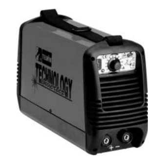
Telwin TECHNOLOGY 150 Troubleshooting And Repair Manual

Telwin TECHNOLOGY 150 Troubleshooting And Repair Manual

Inverter

Advertisement

CONTENTS
REPAIR GUIDE.......................................................10
SPARE PARTS LIST...............................................20
REPAIR SHEET...................................................... 22
" r e p a r a t i o n
TROUBLESHOOTING
TROUBLESHOOTING
TROUBLESHOOTING
TROUBLESHOOTING
AND REPAIR MANUAL
AND REPAIR MANUAL
AND REPAIR MANUAL
AND REPAIR MANUAL
PAGE
2
3
5
6
10
11
11
14
17
n o
inver ter
p r o b l e m ! "
cod. 988588

Advertisement

Table of Contents
loading
Need help?

Need help?

Do you have a question about the TECHNOLOGY 150 and is the answer not in the manual?

Questions and answers

Subscribe to Our Youtube Channel

Summary of Contents for Telwin TECHNOLOGY 150

  • Page 1: Table Of Contents

    cod. 988588 inver ter TROUBLESHOOTING TROUBLESHOOTING TROUBLESHOOTING TROUBLESHOOTING AND REPAIR MANUAL AND REPAIR MANUAL AND REPAIR MANUAL AND REPAIR MANUAL CONTENTS PAGE OPERATION AND WIRING DIAGRAMS....2 Block diagram Analysis of the block diagram Illustrations Wiring diagrams REPAIR GUIDE............10 Equipment required General repair instructions Troubleshooting and remedies Testing the machine...
  • Page 2: Operation And Wiring Diagrams

    TECHNOLOGY 150-170-200-186CE/GE OPERATION AND WIRING DIAGRAMS OPERATION AND WIRING DIAGRAMS OPERATION AND WIRING DIAGRAMS OPERATION AND WIRING DIAGRAMS BLOCK DIAGRAM - 2 -...
  • Page 3: Analysis Of The Block Diagram

    Converts the alternating mains voltage to continuous pulsed Consisting of: CY1, CY2. voltage (N.B. No D3 present on Technology 150). Prevents noise from the power source from being transmitted through the welding cables and vice versa. Block 3 Block 11...
  • Page 4 TECHNOLOGY 150-170-200-186CE/GE TECHNOLOGY 150-170-200-186CE/GE Block 17 Block 25 Alarm LED Overvoltage safeguard Consisting of: U3A, R62, R68 (primary board). Consisting of: D9 (primary board). It is switched on by block 16 (alarms) in the event of: If the main supply voltage exceeds the maximum value this safeguard triggers (a tolerance of approx.
  • Page 5: Illustrations

    TECHNOLOGY 150-170-200-186CE/GE TECHNOLOGY 150-170-200-186CE/GE ILLUSTRATIONS Primary board (19) RECTIFIER FILTER (25-26) FUNCTIONS FILTER BRIDGE OVER/UNDER VOLAGE SELECTOR (18) CHOPPER SAFEGUARD CURRENT POTENTIOMETER (17) ALARM (11) (12) HYBRID BOARD FLY-BACK DRIVER (24) PRE-CHARGE POWER SUPPLY IGBT GALVANIC CHOPPER CURRENT SEPARATION TRASFORMER...
  • Page 6: Wiring Diagrams

    TECHNOLOGY 150-170-200-186CE/GE WIRING DIAGRAMS General wiring diagram - 6 -...
  • Page 7 TECHNOLOGY 150-170-200-186CE/GE TECHNOLOGY 150-170-200-186CE/GE Wiring diagram primary board - Power Schema elettrico scheda primario - Driver - 7 -...
  • Page 8 TECHNOLOGY 150-170-200-186CE/GE Wiring diagram primary board - Power supply Wiring diagram primary board - Driver - 8 -...
  • Page 9 TECHNOLOGY 150-170-200-186CE/GE TECHNOLOGY 150-170-200-186CE/GE Wiring diagram hybrid board Wiring diagram secondary board - 9 -...
  • Page 10: Repair Guide

    5 Differential probe 1/200 6 Hall Probe cod. 802406 7 HV Power supply cod. 802403 USEFUL INSTRUMENTS 8 Unsoldering station 9 Miscellaneous tools (*)The instruments with codes can be supplied by Telwin. The sale price is available on request. - 10 -...
  • Page 11: General Repair Instructions

    (the circuit on the primary board supplying H) The boards (repaired when necessary) and the wiring should auxiliary voltages), even when the machine is operating at low never be modified without prior authorisation from Telwin. voltage. I) For further information on machine specifications and It is easy to build using the electrical diagrams in fig.
  • Page 12 To do this, take the cables between finger and thumb (as close as possible to the fastons or connectors) and pull outwards present on Technology 150); gently: the cables should not come away from the fastons or thermostat ST1 on secondary diode dissipator;...
  • Page 13 The board is identified by a 6-digit code (printed in white on the · 10V/Div; · 10 sec/Div. µ component side after the initials TW).This is the reference code for requesting a replacement: Telwin may supply boards that are VERIFY THAT compatible but with different codes. · POSITIVE AMPLITUDE WARNING! before inserting a new board check it carefully for IS +18V ±10%;...
  • Page 14: Testing The Machine

    TECHNOLOGY 150-170-200-186CE/GE separate the base from the machine structure as follows: Please read the procedure for replacing the IGBT's - with the machine disconnected from the main supply undo the 4 carefully (fig. 3). side screws (2 on the front and 2 on the back) that attach the The 4 IGBT's are attached to 2 different dissipators and whenever board to the base;...
  • Page 15 For the Technology 150 the waveforms displayed on the oscilloscope resemble the waveforms displayed on the oscillscope resemble those in those in Fig.
  • Page 16 TECHNOLOGY 150-170-200-186CE/GE For the Technology 170 FIGURE K FIGURE E the waveforms displayed on the oscillscope resemble those in Fig. I SETTINGS the output current is equal to +160Adc ±3% and the output · PROBE CH1 x100; voltage is equal to +26.4Vdc ±5%; if the output current reading ·...
  • Page 17: Illustrations

    TECHNOLOGY 150-170-200-186CE/GE TECHNOLOGY 150-170-200-186CE/GE conditions for the particular Technology model (see tables at point C)Welding test 1.2 D), switch on the machine and leave it running until the MMA: with the machine set up according to the instructions in the thermostatic capsules trigger (machine in alarm).
  • Page 18 TECHNOLOGY 150-170-200-186CE/GE FIG. 2A YELLOW LED SWITCH ALARM SELECTION TIG/LIFT-HARD-SOFT CURRENT POTENTIOMETER BOTTOM BOTTOM COVER SCREWS COVER SCREWS BOTTOM POSITIVE DINSE NEGATIVE DINSE COVER SCREWS FIG. 2B GENERAL SWITCH MAINS CABLE BOTTOM BOTTOM COVER SCREWS COVER SCREWS - 18 -...
  • Page 19 TECHNOLOGY 150-170-200-186CE/GE TECHNOLOGY 150-170-200-186CE/GE FIG. 3 R40B Q10 SW1 R16 Q4, Q3 D5, D3 C7, C2, C4, C6 CN10 ISO2, ISO1 Q2, Q1 K2, K1 HYBRID BOARD FIG. 4 R1, C1 SHUNT R1 D1, D2 THERMOSTAT D3, D5 CABLE - 19 -...
  • Page 20: Spare Parts List

    TECHNOLOGY 150-170-200-186CE/GE ELENCO PEZZI DI RICAMBIO - LISTE PIECES DETACHEES SPARE PARTS LIST - ERSATZTEILLISTE - PIEZAS DE REPUESTO Esploso macchina, Dessin appareil, Machine drawing, Explosions Zeichnung des Geräts, Diseño seccionado maquina. Per richiedere i pezzi di ricambio senza codice precisare: codice del modello; il numero di matricola; numero di riferimento del particolare sull'elenco ricambi.
  • Page 21 In order to improve the service, each servicing centre is requested to fill in the technical card on the following page at the end of every repair job. Please fill in this sheet as accurately as possible and send it to Telwin. Thank you in advance for your co-operation!
  • Page 22: Repair Sheet

    TECHNOLOGY 150-170-200-186CE/GE Official servicing centers Repairing sheet Date: Inverter model Serial number: Company: Technician: In which place has the inverter been used? Building yard Workshop Others: Supply: Power supply From mains without extension From mains with extension m Mechanichal stresses the machine has undergone to...
  • Page 23 TELWIN S.p.A. - Via della Tecnica, 3 36030 VILLAVERLA (Vicenza) Italy Tel. +39 - 0445 - 858811 Fax +39 - 0445 - 858 / 858 E-mail: telwin@telwin.com http://www.telwin.com...

This manual is also suitable for:

Technology 170Technology 200Technology 186 ce/ge

Table of Contents