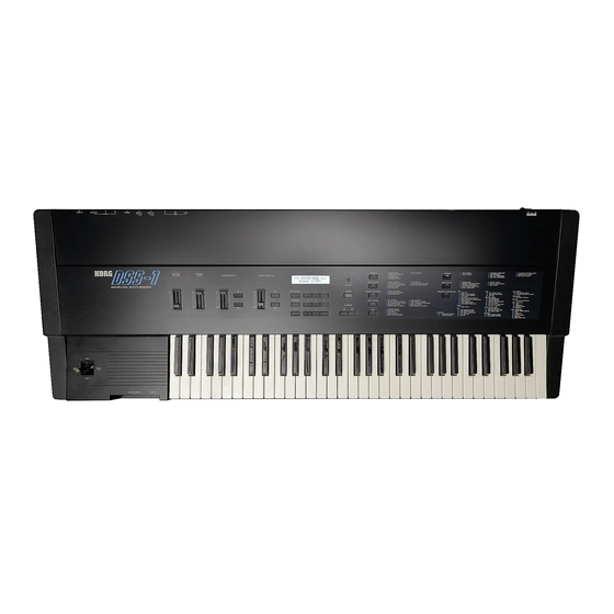
Korg DSS-1 Owner's Manual
Digital sampling synthesizer
Hide thumbs
Also See for DSS-1:
- Owner's manual (313 pages) ,
- User manual (312 pages) ,
- Service manual (74 pages)
Table of Contents
Advertisement
Quick Links
Advertisement
Table of Contents

Related Manuals for Korg DSS-1


Summary of Contents for Korg DSS-1
- Page 1 DIGITAL SAMPLING SYNTHESIZER OWNER’S MANUAL...
- Page 2 Congratulations and thank you for choosing the K O R G D S S Digital Sam pling Synthesizer. Please read this m anual carefully to obtain optim um performance and help assure long term reliability. BASIC PRECAUTIONS ■Handle Gently ■Place of use: Switches, knobs and other controls are designed to Avoid using this unit exposed to the following condi...
-
Page 3: Table Of Contents
2. Making the Raw Materials (sounds) for a Multisound 3. Completing Your Multisounds 4. Using the Completed Multisounds DATA MANAGEMENT 1. DSS-1 Memory, Data Structure, and System s _ 2. Floppy Disks and Data Management ~ GENERAL OPERATION 1. Overview of the Operation modes 2. -
Page 4: Features & Functions
■ DATA ENTRY B MASTER VOLUME * MASTER TUNE These sliders are used to adjust the Used for tuning the DSS-1 Volume control for syn values of parameters, to make selec to match the pitch of other thesizer’s sound ouptut. - Page 5 If none of the mode key LEDs are display, try turning this knob DSS-1. illuminated, then the DSS-1 is operating in the PLAY clockwise. mode. The functions available within each mode are shown in the function list to the right of each of the mode keys.
-
Page 6: Rear Panel
-■ POWER SWITCH MIDI CONNECTORS AC CORD SOCKET PROGRAM UP JACK IN, OUT, THRO Connect the supplied Turns DSS-1 power on For connection of a loot AC power cord to this and off. For connection to other switch to advance the pro... - Page 7 AUDIO IN JACK PHONES JACK OUTPUT DAMPER JACK Input for audio signal (from RIGHT JACK, LEFT JACK, For connection of a Plug stereo head microphone, tape, etc.) to be LOW/HIGH SWITCH foot switch to act like phones in here. sampled. Audio output jacks and output level a piano damper pedal.
-
Page 8: Disk Drive & Floppy Disks
Ì.D is k Drive & Floppy Disks 1 _ DISK DRIVE... - Page 9 ★ Please save the head protection sheet that was in the disk drive. Always remove any disk and put this sheet sheet in the drive before transporting the DSS-1 * Store the protection sheet in a clean environment and give it the sam e care that you would your floppy disks.
- Page 10 • Never place anything on top of a floppy disk. The disk may become deformed and unusable. ■ About the WRITE PROTECT HOLE * The kind of floppy disk used in the DSS-1 has a "write ★ Write Disable position protect hole” which, when open, prevents you from erasing or changing disk data.
- Page 11 ■ Which disks to buy * Typical label of type of disks usable in the DSS-1 • The DSS-1 uses 3.5-inch double sided, double den sity, double track micro-floppy disks. When you buy MF2DD more disks, check for a label that says: MF2DD, D O U B L E SID ED , D O U B L E D E N SIT Y , D O U B L E •...
-
Page 12: Before Performance
BEFORE PERFORMANCE 1 .Basic Setup_____ ■ Set up the DSS-1 a s described below to enable play. - Page 13 3; Turn down the volume all the way on the DSS-1 as well as on the connected amps, mixing con r f e = r n soles, and other equipment. Then turn on the power on the DSS-1 and other equipment.
-
Page 14: Basic Operation
■ The P R O G R A M S E L E C T procedure is performed in • When play mode is selected. the P L A Y mode. The DSS-1 is in the P L A Y mode when none of the mode selector key L E D s are on. - Page 15 First prepare to begin as described in the Basic Setup section. Then follow the steps below. Operation Operation of DSS-1 j) Insert the disk in the drive. X Confirm that the S Y S T E M mode is selected* •...
- Page 16 ^ There are lour system s per disk. These are named A, B, C, and D.Use the DATA E N T R Y A to select one of these systems. data en try a Currently selected system. à Use to select System % After selecting a system press the E N T E R key.
- Page 17 S Y S T E M mode and extinguish its LED. Press • Cancels S Y S T E M mode and switches DSS-1 to P L A Y mode. LED is on. When SYSTEM mode is cancelled.
- Page 18 If you input an “illegal*1 number such as 00 or 34, • Example: If you try to select number 34. then the DSS-1 ignores the second digit and keeps waiting until you enter a second digit that is a valid program number.
-
Page 19: Performance Functions
Ts] After Touch ■ The DSS-1 has programmable after touch. This is ac cessed by pressing down on keys after playing them. After touch can be programmed to control vibrato depth, volume, brightness, and other aspects of the sound. - Page 20 The current value of the transpose parameter is shown on the display as a tone name from F # to F. Procedure for using transpose: Operation Operation of DSS-1 Confirm that the unit is in the play mode. : 2} Press the enter key. ENTER...
- Page 21 While holding down the enter key, press any key on the keyboard. e n t e r Hold down | The value changes according to the key that you Press and Release played. The display confirms the change, if any. (Here F# was played so there is a six semitone 'downward transposition.) r S KEY TRANSPOSE:F#...
- Page 22 Damper ■ An optional toot switch such as the PS-1 or DS-1 may be connected to the rear panel damper jack to serve as a damper pedal like that on a piano* Depending on the program, this can also be used to obtain a hold ef fect (so that a note is held for as long as you press on the foot switch, even if you release the key on the keyboard).
-
Page 23: Creating Sounds
Tj Basic arrangement of the D SS-1 and how it affects the sound. • Basic configuration of DSS-1 I A s in a traditional analog synthesizer, the DSS-1 gives you the convenience of a subtractive technique whereby the oscillators provide an audio signal which is processed by the V C F and VCA. - Page 24 The sound source (multisounds} of the OSS-1. ■ The DSS-1 stores its waveforms as digital data in memory. When a sound is to be used, the data is read from this “wave memory” and converted into an analog signal which is output by the oscillator. Actual...
- Page 25 The data is read only once; it is not repeated. START This portion of the waveform data is read repeatedly. • DSS-1 multisound concepts ■ A s we have described, the DSS-1 sound sources are produced by several waveforms assigned to par ----------------------- Multisound —...
- Page 26 Making multisounds ■ We now know that the DSS-1 multisounds are made • Two groups of tasks involved in making a multisound: up of a number of sounds assigned to sections of the keyboard together with the multisound parameters i) A s its name implies, a multisound is made up of that control how the sound data is read from memory.
-
Page 27: Making The Raw Materials (Sounds) For A Multisound
. Making the Raw Materials (sounds) for a Multisound_________________ Sam pling Takes an actual ■ This function lets you take a sound signal from out The sampling function sound signal and side the synthesizer and store its waveform data in stores it as digital memory. - Page 28 ■ The sampling frequency is the number of samples • Relationships between the sampling frequency, taken per second. For instance, a 32kHz sampling resolution, and memory requirement. frequency means that 32,000 samples are taken Lets say we have a waveform like this that contains a each second (that is, one sample every 0,00003125 lot of harmonic detail.
- Page 29 ■ The DSS-1 lets you choose any one of four sampling • What happens to sound quality at the 16kHz sampl frequencies, at 16kHz, 24kHz, 36kHz, and 48kHz. ing frequency? Make your choice based on your need for high range Here we have the sam e sound recorded at two dif...
- Page 30 ± m m m ■ The DSS-1 lets you create sounds in two ways: by ad- • Two ways to create waveforms: ditive harmonic synthesis, and by "hand drawing.” Additive...
- Page 31 ■ With additive synthesis, you set the level of each of • Additive synthesis 128 harmonics (each of which is a simple sine wave that is a harmonic multiple of the first or fundamental 1st harmonic^ frequency.) The result is one full cycle of a complex (fundamental) waveform.
- Page 32 ■ In the hand drawing method, you use the data entry A * Hand drawing slider to create one full cycle of a waveform. This lets you create waveforms that have more complex har monic content than is possible to obtain with the ad ditive synthesis method.
- Page 33 • A/D resolution of waveforms created by additive syn While external waveforms are quantized over a range of 4096 steps, fewer steps are used to represent the thesis or hand drawing. level of each sample in waveforms produced by additive Created sound Recorded sound synthesis or hand drawing.
- Page 34 Truncation offers a way of getting a single full cycle from a sampled waveform. Both the additive synthesis and hand drawing methods give you just a single full cycle to start with. You get a single full cycle. If you are going to loop or link a truncated waveform Using the truncate function's auto zero cross search then you may want to take advantage of the truncate function.
- Page 35 ■ The link function (iii) lets you put together two sounds. It doesn't matter how you obtained the sounds in the first place (sampled, created, or edited), you can link them together to create a new sound. Show n here are some examples of the power of this function.
- Page 36 For gradual transitions between the linked sounds, you • Link cross fade can use the link cross fade function. This is only effec tive when both of the waveforms to be linked are suffi Example: Linking piano attack to string sustain. cie n tly long.
- Page 37 ■ The mix function (iv) lets you mix together two • The mix function sounds* You can determine the ratio of the mixture Example: Grass plus strings Example: aquare wave plus sawtooth and detune them if you like. — , wave F o r e x a m p le , you c a n m a k e a fat, p h a se d s o u n d b y mixing a sound with a detuned copy of itself.
- Page 38 This function is usually used to make changes in stored * Using the view/edit sample data function. waveforms. Example: Making an alteration in a waveform. However, you can also use it to create a completely dif ferent waveform, a relatively easy matter if you are deal We need to fix up the tail ing with a single cycle.
-
Page 39: Completing Your Multisounds
T O P parameter you assign these sampled sounds to • Ohginal/Top key assignments and memory readout the DSS-1 keyboard. Ordinarily, the O R G or "original range. key" value is set to the key that has the sam e pitch as the sampled sound. - Page 40 (F for example) in each octave. Then use each Sounds obtained by sample for one octave of the DSS-1 keyboard. In this sampling. case, you set the original key to the sam e note (F) as the sample, while the top key may be assigned a half octave higher (B).
- Page 41 ■ n ) TR/NT (transpose or no transpose) is a question of whether to transpose a sound’s pitch or not. Of course, you would normally set this to TR, so that the pitch will be transposed and correspond to the key being played.
- Page 42 "\ the very end of the sample and set the length to 1. After reproducing the entire sound, the DSS-1 wilt start to loop this single piece of data, but since there is no change in the level, there is no alternation in the waveform and so no audible sound.
- Page 43 • Sound start & length ■ V) The sound start & length parameters let you decide which portion of each sound to use. The sound start point is specified as a memory address. ----------- You don't want these portions— —--------- to be reproduced.
- Page 44 ■ The sounds assigned to the keyboard in this mufti- * Sounds with loop on. (Long loop or short loop.) sound were obtained by sampling and then trun cating to remove the unneeded portions of the sampL ed sounds- This is the usual procedure when attemp ting to reproduce acoustic instrument sounds.
-
Page 45: Using The Completed Multisounds
4-Using the Completed Multisounds ; I Multisounds and Synthesizer Operation ■ A s we have described, up to 16 sounds may be ■ From here on you can use the D SS-1 in almost exact assigned to the keyboard in each multisound- Fur ly the sam e way as a conventional analog synthe... - Page 46 For example, if you put b a ss in the lower part of the • Example: Here we have a looped multisound with bass in the lower half and organ in the upper half of keyboard and put organ in the upper half, then you the keyboard.
- Page 47 ♦ How to make 30 sam ples available in one keyboard. ■ W hen attempting to reproduce the sound of acoustic instruments by using sampled sounds, best results I) Assign 15 sounds to the left half of the keyboard. are achieved by taking many samples and assigning Assign one "length 1, level 0 ”...
-
Page 48: Data Management
DATA MANAGEMENT l.D S S -1 M em ory, Data Structure, and Systems_________________________ [T DSS-1 memory arrangement and data storage ■ DSS-1 internal memory is divided up into three main sections; These wave memory, program memory, and the program output buffer. This ar... - Page 49 This prevents the VCF, EQ, D D L and other parameters from changing the sound. Program data is * In addition, the DSS-1 also has a portion of memory transferred from pro- reserved for the MIDI parametes. (We may call this...
- Page 50 • System structure System PROGRAM ■ The DSS-1 can hold a maximum of 16 multisounds in OUTPUT wave memory at one time. It also holds 32 programs BUFFER in program memory. The currently selected pro gram is transferred to the program output buffer to...
- Page 51 To allow more multisounds to be stored in wave ■ Use the truncate function to remove unneeded parts memory and be available to the programs in each of the sounds that are the components of each of the system, it is necessary to conserve memory space. multisounds.
-
Page 52: 2. Floppy Disks And Data Management
| Data structure on D SS-1 floppy disks. In the diagram, the multisounds (M.SND) that are ■ The DSS-1 has a built-in floppy disk drive. This is us marked with an “(a)1 ' will be loaded into the D S S - V s ed to store and retrieve your waveform and program memory when you “get“... - Page 53 2|Sound, m ultisound nam ing ■ Each sound and each multisound are given a name that is up to eight characters in length. Data is then handled under that name. The same name can not be used for different data {of the sam e type) on the same disk.
- Page 54 [3]Functions concerned with moving data to and I from disk. Direction of Memory to Disk ffiNotes Disk to Memory movement Data One set for all four systems on a (1) SAVE SYSTEM (SYSTEM MODE (1> GET SYSTEM (SYSTEM MODE single disk. The most recently stored para...
-
Page 55: General Operation
* Initial d is p la y in the s a m p le m ode. an audio signal received through the AUDIO IN jack on the DSS-1. This process is called “sampling.” The sampled sounds are stored in wave memory and used to produce a multisound. - Page 56 • Parameters of Multisounds Produced in the Create Waveform Mode ■ Only a single multisound is produced in the create Multisound name: ! NO-NAME waveform mode. For this purpose wave memory is 1020 L O O P ON Multisound length: used as the work area, so ail previous resident data is destroyed.
- Page 57 ¡4 Multisound Mode Functions in the multisound mode. * initial display for multisound mode, there are three categories of functions available in the multisound mode. 1> w hen multisound exists in wave memory. A. The production of multisounds. This lets you get sounds from disk and use them to assemble a multisound in wave memory.
- Page 58 ■ When you use the program change function, you are replacing the program output buffer memory con tents with a program from program memory. is simply copied from data program m em ory to buffer. The data previously in the buffer is erase. If you make changes to the current program and do not want to loose those changes, then you must write the changed data back to the program memory before...
- Page 59 ■ The normal procedure for making a system for perfor mance on the DSS-1 is as follows. System structure 1. In the system mode, assemble the muitisounds that you will need. 2. In the system mode, assemble the programs Program memory.
-
Page 60: Example Applications Of Modes
.Example applications of modes t To just listen. Create waveform Sample made "\ mode You can listen to the sound that you sampled or created. [2]To set up a patch (create a tone color). Create waveform Sample mode mode You use the V C A t VCF, And other parameters to pro .. -
Page 61: Sample Mode
! . 7 S h . S s « ‘ ( 2j Initial Operation Operation Operation of DSS-1 Press the S A M P L E key to select the S A M P L E mode. S A M P l. r... - Page 62 '3 Press the E N T E R key to finalize your choice. E N T E R Press You are now prompted for the total time for the recor ding. E N T E R V I f Flashing Use the C U R S O R keys to move the cursor (the underline in the display) to your choice.
-
Page 63: 2, About Each Of The Functions
¿.About Each of the Functions rFOSAM PLEIrani ill About the sample start function Example: Using a memory division of 8. ■ Sam ples the signal from the AU DIO IN jack and stores that sample in the memory block with the sample number specified by the F1 S A M P L E NO, /MEM DIV, Memory block as specified by sample number function,... - Page 64 Press the number o key in the 10-key pad. This selects the sample start function. Press • The DSS-1 stands by for sample start. indicates sample start lunction. Confirm the sample number, memory division, sampling frequency, and original key. Then press E N T E R when you wish to finalize these settings and go ahead with sampling.
- Page 65 3 Input the sound that you wish to sampte. • The DSS-1 begins sampling when the input signal level exceeds the trigger level. It automatically stops sampling at the end of the selected sampling time. • Then it asks if you wish to try over again.
- Page 66 Operation of DSS-1 i) Press the D E L/C A N C E L key. • This aborts the operation so the DSS-1 stops waiting D C L / C A N C E L for the input signal to exceed the trigger level. It then...
- Page 67 Fl SAMPLE NO./MEM. DIV ri ; Sample number and memory division function. ■ Setting the memory division and setting the sample A. The function of memory division setting. number are different operations though they appear B. The function of sample number setting. in the sam e initial prompt.
- Page 68 This can be done automatically or manually. With the that block. When this occures it is usually misinterpreted "A u to a ssig n method, the DSS-1 assigns each ’ 1 as a malfunction.
- Page 69 | 2 ] Sample number and memory division function procedures. A. Memory division setting/how to change. Operation of DSS-1 Operation O' Confirm that the S A M P L E mode is selected and When in the sample mode. that you have completed the INITIAL opera...
- Page 70 Use DATA E N T R Y A to select the memory divi sion. d a t a e n t r y U se to select Show s current value and waits for further input. Memory Division MEM,, DIU SMPL-NÜ.
- Page 71 Press the Y E S or N O key to reply, * Press the Y E S key if you desire automatic assignment. T E S All memory blocks are assigned automatically (as Press datailed in the previous section on the auto assign function).
- Page 72 % Use the cursor keys to move the cursor to the parameter (original key or top key) that you wish to adjust. Use DATA E N T R Y A to adjust the value. C U R S O R sriPLîHl DIU.Ü08 Use these to select Y E S...
- Page 73 Use the Y E S and N O keys to reply. * To continue to assign memory blocks, press YES. Press • This takes you back to the situation in step Pro- cede from step ? . ■ to assign the next memory block. ★...
- Page 74 ■ If memory blocks are left over after interrupting Example: Suppose you interrupted the procedure after manual assignment, then the DSS-1 automatically assigning memory blocks up through sample assigns them in semitone steps to the keys im number 3. mediately above the "top key" assigment of the last assigned memory block.
- Page 75 B. Selecting the sam ple number. Operation Operation of DSS-1 Confirm that the S A M P L E mode is selected and * The S A M P L E key L E D lamp should be illuminated. that you have completed the INITIAL opera...
- Page 76 F2 ATTN/GAIN 1: The attenuatfon/gain function ■ This is used to control input signal level so that it is suitable for sampling. ■ You set the ieveis for two parameters: gain and at“ tenuation. Available gain values "Gam '* is the amount of amplification applied to the signal.
- Page 77 Procedures for setting attenuation and gain. Operation Operation of DSS-1 Q Confirm that the S A M P L E mode is selected and • Indicates S A M P L E mode. that you have completed the INITIAL opera...
- Page 78 The trigger level setting is marked by a single star (*}. ■ The input signal is ajso routed to the DSS-1 outputs so you can monitor it by ear as well. ■?J Trigger level function procedure.
- Page 79 2 ) Use DATA E N T R Y A to set trigger level D ATA E N T R Y A Current numeric value of trigger level. Use to select Trigger Level Trigger level relative to bar graph meter indication,...
- Page 80 F4 ORIGINAL/TOP KEY L i) About the origlnal/top Key function. ■ This lets you change memory block assignments to (Example; memory division is the keyboard. These memory blocks and their sam ple numbers are specified by the F I S A M P L E NO. Memory block specified by sample number /MEM.
- Page 81 Using the original/top key function. Operation Operation of DSS-1 ö ■ Confirm that the S A M P L E mode is selected and • Indicates S A M P L E mode. that you have completed the INITIAL opera...
- Page 82 ........J Using the save sample function. Operation Operation of DSS-1 o ; Confirm that the S A M P L E mode is selected and • Indicates S A M P L E mode. that you have completed the INITIAL opera...
- Page 83 Use DATA E N T R Y A to select the sample number that you wish to save to disk. DATA E N T R Y A ♦ . Selected sample number appears here >*££.! Use to select Sam ple Number (3;...
- Page 84 4- Input a name by using the cursor keys and DATA E N T R Y A. D ATA E N T R Y A C U R S O R V E S Si'IPU @i DIM U se to name Input Nane!TE5T-#t Name appears here.
- Page 85 ; Press Y E S or N O key, ★ To save, press Y E S, Press • Display a sks you to wail while saving to disk, • Then you are asked whether you wish to continue to use the save sample function. b a v in 9 P le a s e Uait- i'11 n u le...
- Page 86 (If you had aborted before quitting, then the display says "Aborted” .} Shows you can select the function. ■ If you tell the DSS-1 to save to disk and it finds that Display when you try to save using a name that...
- Page 87 Operation Operation of DSS»1 i) Use the Y E S and N O keys to reply. ★ If you press Y E S then the old sound will be deleted and the new sound {in wave memory) having the sam e name will be saved in its place on the disk.
-
Page 88: Create Waveform Mode
Using the draw waveform function. Operation Operation of DSS-1 • Check key to see that LE D is on, '& ■ Confirm that the C R E A T E W A V E F O R M mode is selected. - Page 89 Press the number 1 key to select the draw waveform function. The display confirms the selection of function T Press [ It tells you to draw with slider A and tells you to press E N T E R to start. Shows draw waveform function.
- Page 90 — Play the sound on the keyboard and decide whether to keep the wave or try again. Press Press the Y E S key to draw the wave again. This takes you back to step z , above. * Press the N O key if you want to keep the wave and go ahead.
- Page 91 * If you do not want to edit the waveform then press the N O key. Press ★ This completes the draw waveform function and the display prompts you to select a function. FI UHUEF0RI1 Drawn ■”iï—1 Ì h*5 ! . { . ' . ! ■■■...
- Page 92 [2] About the harmonics tables. "current harmonics table" where you can work on it ■ The DSS-1 offers you a choice of harmonics tables to with the harmonic synthesis and editing functions. use as the basis for harmonic synthesis. There are six initial choices.
- Page 93 ] Using the harmonic synthesis function. Operation Operation of DSS-1 ,P} Confirm that you are in the C R E A T E W A V E Indicates C R E A T E W A V E F O R M mode.
- Page 94 Press EN TER to finalize your selection, ENTER Press DSS-1 performs harmonic synthesis using the har monic table. A fte r c o m p le tin g th e s y n th e s is , it lets you edit the har...
- Page 95 ^ Use DATA E N T R Y A to selecct the harmonic. D ATA E N T R Y A U se to select Display shows current harmonic and its current level. Harmonic (This example shows the 11th harmonic and that its level is set to 0.) I—...
- Page 96 Repeat steps © a rid to select harmonics and adjust their levels. • Press E N T E R to finalize your adjustments. E N T E R _ i_Lt_ • The D SS-1 then synthesizes the waveform based on P re s s the harmonic levels that you set in the previous steps* After completing the calculation, it takes you...
- Page 97 Using the save waveform function. Operation Operation of DSS-1 C Q ; You must be in the C R E A T E W A V E F O R M mode • The C R E A T E W A V E F O R M key's indicator is il...
- Page 98 2 Use the DATA E N T R Y A slider to choose the waveform that you wish to save to disk. DATA ENTRY A U se to select Waveform Show s the selected waveform number Shows its original key. Press the E N T E R key to finalize your choice.
- Page 99 4 Use the cursor keys and DATA E N T R Y A to input a name. D ATA E N T R Y A C U R S O R y e s l i § Use to input name Display shows name in this area.
- Page 100 ù Press the Y E S or N O key to reply. * To save, press Y E S. Press • Display asks you to wait while siv in g to disk. • Then you are asked whether you wish to continue to use the save waveform function.
- Page 101 (If you had aborted befor quitting, then the display sa y s “Aborted1 '*) • If you press Y E S in step (6), then DSS-1 first checks the disk directory to see if the name that you entered already exists. If it finds a waveform of the same name, then it sk s you whether it is okay to delete that sound or not.
-
Page 102: Edit Sample Mode
EDIT SAMPLE MODE 1. About Each of the Functions I FI SELECT SAMPLE I 1 Select Sam ple Function. ■ This loads or transfers multisounds to the edit work A. Getting a sound from wave memory. area from the wave memory area or from a disk. T h is' is necessary to allow editing using functions F3 M.S.01 M.S.02... - Page 103 [2 Using the select sample function. A, Getting a sound from wave memory. Operation Operation of DSS-1 (Q -1 Confirm that the ED IT S A M P L E mode has • Indicates ED IT S A M P L E mode, been selected.
- Page 104 Make sure that the cursor is under the M E M O R Y side of the display, then press ENTER. E N T E R V t s Press • The display readies for multisound selection. The lower line shows the multisound number, name, and length.
- Page 105 P re s s E N T E R to fin a liz e y o u r c h o ic e . E N T E R Press * This completes multisound selection and advances to sound selection. Shows multisound number and name.
- Page 106 © P r e s s E N T E R to fin a liz e y o u r s e le c tio n . E N T E R Press * After the sound is selected you are asked whether to go ahead and get the sound into the work area.
- Page 107 * If you check the status of the sound and decide not to load it to the work area then press the NO key. r«0 This stops the process of getting a sound and aborts Press the select sound function. You are returned to step 0 and prompted to select another function or mode.
- Page 108 ■ ?! Use DATA E N T R Y A to select the key assign ment conditions. DATA ENTRY A — U se to select Key Assignment Shows currently selected key assignment fp > After setting key assignment, press EN TER- E N T E R Press •...
- Page 109 B. Getting a sound from disk. Operation Operation of DSS-1 ® confirm that the EDIT SAMPLE mode has been • Indicates EDIT SAMPLE mode. selected. The EDIT SAMPLE key should be lit. EDIT SAMPLE ' L — — • The display pormpts you to choose a function. (See section on conditions of function selection, page ©...
- Page 110 3; Press EN TER. E N T E R Press * This selects disk and starts a search on the disk. Then you are prompted to use DATA E N T R Y A to select a sound. I I I '"iM .-ir'F ■**<...
- Page 111 Press E N T E R to finalize choice. E N T E R Press • The DSS-1 reads the length and sampling frequency of the sound and displays this data with the name of the sound. You are asked whether you wish to get this sound to the work area or not.
- Page 112 * If after checking the status you decide not to load, then press the N O key. • This aborts the function and returns you to step Press where you can either select another function or change modes. Shows you can select another function. Use the C U R S O R keys to select key assign...
- Page 113 t Use DATA E N T R Y A to set key assignment. DATA E N T R Y A Use to select Show s currently selected key assignment. Key Assignment Shows currently selected key assignment, Press E N T E R to finalize setting. E N T E R i U i Press...
- Page 114 AUTO REPEAT Using the truncate start/iength function. Operation Operation of DSS-1 u Go into the ED IT S A M P L E mode. Confirm that Indicates EDIT S A M P L E mode. the ED IT S A M P L E key is lit.
- Page 115 Use the DATA E N T R Y A controls to select ON or O F F as desired. Shows currently selected setting. DATA E N T R Y A ■ Use to select » — 1 Auto repeat...
- Page 116 F3 TRUNCATE START/LEN6TH i Purpose of truncate start/length function. ■ This lets you cut off a piece of a sound that you have EDIT WORK AREA loaded into the work area (using F1). You specify the starting point and the length of the section to be cut out.
- Page 117 Ft. The initial values are 000000 for sound start, and the actual sound length for the sound length. Using the auto repeat on/off function. Operation of DSS-1 Operation C O ; Confirm that the ED IT S A M P L E mode is •...
- Page 118 'i; Use the cursor keys to select the sound start (S.S.) and sound length (S .L ) parameters- Shows you can select automatic truncation C U R S O R U se to select F3 Press EHI io fiuto Truncate start/ length „...
- Page 119 Press the E N T E R key for automatic truncation. ENTER =fciLuLi • The D S S -t truncates the sample according to your Press settings. The display readout says “Searching” dur ing this process. Afterward, the display shows the resulting start and length values of the automatic truncation.
- Page 120 F4 REVERSE SAMPLE [ i! About the reverse sample function. EDIT WORK AREA (WAVE MEMORY) ■ This reverses a waveform loaded into the edit work area. The effect is like a tape played backward. Note: Reversing the sample defeats the F3 truncate sound start and length values.
- Page 121 j Press key 4 to select the reverse sample func tion. P r e s s The display confirms your choise of function and prompts you to press the E N T E R key to execute. Shows the reverse sample function. _____ j..
- Page 122 F5 LINK SAMPLES] : i Purpose of link sam ples function. EDIT W O R K A R E A (W AVE M E M O R Y ) ■ This lets you take a sound that is in the edit work area (having loaded it in with F1) and link it to another sound from disk.
- Page 123 ■ About the Auto Level Adjust capability. This provides smoother connection between the two linked waveforms by automatically finding the first point in the second waveform that has the sam e level as the end of the first waveform. Here there is a point ai me same level as the end of the first waveform.
- Page 124 2 ; Using the link sample function. Operation Operation of DSS-1 fl' Select the ED IT S A M P L E mode. Indicates EDIT S A M P L E mode. t O I T SAMPLE Press the number 5 key.
- Page 125 Take the disk that has the sample that you want to link and put the disk in the drive. Then press ENTER. E N T E R after put Press The display says that it is searching for sounds on the the disk disk.
- Page 126 ■4' After selecting the sound to link, press the E N T E R key to finalize your choice. E N T E R after the Press The D SS-1 checks the length of the sound on the disk selection and shows its value after the name in the display.
- Page 127 Press E N T E R to finalize your load start address E N T E R ■ ' i • The name link address, and sampling frequency of P r e s s the sound to be linked are shown on the display. You are asked whether or not to execute the link.
- Page 128 * If you decide not to load, press the N O key. This will abort the function and ask whether you wish P r e s s to try to link again. Hbort j to L ★ If you wish to adjust the link, press the Y E S key* •...
- Page 129 ★ Press N O if you don’t want to adjust the link. Press You are then asked whether you want a cross fade or not. ★ Press Y E S if you want to adjust the link again. Press # The display repeats the readouts from step & on* ★...
- Page 130 U (): ★ Press Y E S if you want a cross fade. Press The display waits for you to specify a length. UfcUbb F-HDt FADE LENGTH = 000000 E N T E R - Flashes while waiting for you to specify a length. * Press N O if you do not want a cross fade, •...
- Page 132 P r e s s N O if y o u d o n o t w a n t to lin k a g a in . Press • This exits the link sample function and lets y£u choose another function or change modes. (If you press NO in step 7, then the display says Aborted.) Shows yuu can seieci a function.
- Page 133 F6 MIX SAMPLES i . i About the mix sam ples function EDIT W O RK A R E A (WAVE M E M O R Y ) ■ This function is used to mix a sound that has been loaded (by using F1) into the edit work area together with a sound from disk.
- Page 134 W Sounds may be used with A U T O R E P E A T turned off. If the sound being mixed is sufficiently tong, then T U N E affects it as shown in the diagram. M If the sounds being mixed are single fuil wave cycles, then the waveform mixed is affected by T U N E as show n in the diagram.
- Page 135 2 Using the mix samples function Operation Operation of DSS-1 Æ1 Confirm that the ED IT S A M P L E mode is Indicates ED IT S A M P L E mode. selected. E D IT ..-On (D Press key number 6.
- Page 136 '?■ Take the disk that has the sample that you want to mix and put the disk into the drive. Then press ENTER. E N T E R ■ 1 r after putting Press The display will confirm that it is searching for sounds in the disk on the disk.
- Page 137 P r e s s E N T E R t o f i n a l i z e y o u r c h o i c e . E N T E R after the • The DSS-1 reads the length and sampling frequency selection Press...
- Page 138 ★ Press N O if you want to abort, Press • This returns you to step u where you can select another function or change modes. Shows you can select a function. Use the cursor keys to move to the sample con dition that you wish to adjust* c u r s o r V E S...
- Page 139 7 Play the keyboard and monitor the sound while us ing the DATA E N T R Y A controls to adjust the value of the selected parameter. DATA E N T R Y A 2nd SAMPLE CONDITION Use to input RAT 10= 50“...
- Page 140 L E V E L = H -1024 I Using the view/edit data function Operation Operation of DSS-1 O' Select the ED IT S A M P L E mode* • Indicates ED IT S A M P L E mode.
- Page 141 Use DATA E N T R Y A or B to select the address. DATA E N T R Y A DATA E N T R Y B Use to select Show s the data value of selected address. the address J - * .
- Page 142 v Use DATA E N T R Y A or B to adjust the data value- DATA E N T R V A DATA E N T R Y B ¡ ]' !!Ti. i*"- i_ ï T \ / I i t u r v t i * - i i ■...
- Page 143 ■ Using F1 and F8, it is possible to retrieve individual sounds from a completed multisound. ■ If you press Y E S in step (5), then the DSS-1 first checks the disk directory to see if the name that you entered already exists.
- Page 144 ' P re s s Y E S if y o u w a n t to r e n a m e . Vf s Press • The display waits for you to input a name — V ”- .Ï.L i”!i ' ! •...
- Page 145 3 Use DATA E N T R Y A to input a name. DATA E N T R Y A • l-H Si-Uh u n i a v a ! j TÌ:U 1 Ca . " ! * ■ Use to input .
- Page 146 P r e s s Y E S t o s a v e . Y E 5 Press The data is saved to disk. You can now select another function or change modes. f ' " 1 - M t :::ri n i M , i I ' / | , m «...
-
Page 147: Multisound Mode
M U LTI S O U N D No. 1 in the “system " resident in the D S S -1 . (Multisounds previously present in the DSS-1 resi dent system are all lost.) ■ The G E T S O U N D function is cancelled If the number of sounds in the multisound under construction ex... - Page 148 Using the get sounds function Operation Operation of DSS-1 Indicates M U L T IS O U N D mode. O' Select the M U L T IS O U N D mode. M U L T I S O U N O r-T \ i Press the 0 key.
- Page 149 2' P r e s s Y E S if y o u w a n t to g o a h e a d w ith lo o p o n . Press • After searching for sounds on disk, the display tells you to use DATA E N T R Y A to select.
- Page 150 ' > Use DATA E N T R Y A to select a sound to load. D ATA E N T R Y A ■ » »I i>l ilr it. ■ l i t iji ■■ f i'— t.- : —...
- Page 151 6, Use DATA E N T R Y A or B to adjust the length of the sound that you want to load. DATA E N T R Y A DATA E N T R Y B U se to select the length of the sound Select the lenylh of the sound that you want to load.
- Page 152 s Press Y E S to go ahead and get the sound. Press After loading you are free to change the key assignments. ï r i . H r i 'i rV..J i l ÿ t d e i r l è...
- Page 153 Move the cursor to the parameter that you want .• “ s to change. c u r s o r f* 0 v M > Use to select • You can select the parameter after moving the cursor. Parameter E N T E R Cursor is under selected Flashing.—...
- Page 154 £ Play the keyboard, check the sound, and press the Y E S key if you are satisfied. V F 6 • If you want the sound, press NO P re s s ★ If you don't want the sound, press NO. P re s s T h is is a s k in g if you w ish to get a d iffe re n t so u n d for the cu rre n tly d is p la y e d so u n d n u m b er.
- Page 155 * If you don’t want to continue to get sounds, press NO. N ' . ? You can now select another function or change modes. Press U I B 4|» « ■ J|B|B 141 + P - y n . b H u * ' * x h - * 1 Shows you can select a function.
- Page 156 $ Press Y E S to go ahead and get sounds. V f e $ Press This lets you repeat the procedure from step \* * ■ ■ ■ i":-. r' i..r ii"..ìk F" t i eie, !”ri. "¡Si-i’i'' !.
- Page 157 FI SELECT M. SOUND SOUND V The select multisound/sound function M.S.01 M .S.0 3 M S . 02 ■ This lets you select from wave memory the multi- .sound for use with F2 through F 9 P and then the sound for use with F2, F 3 P F 4 P F6, F 7 1 and F8, ■...
- Page 158 2 Using the select M. sound/sound function Operation Operation of DSS-1 P Select the M U L T IS O U N D mode. Indicates M U L T IS O U N D mode. M U I II S C H IN D \ I / Press the number 1 key.
- Page 159 To change a m ultisound 3 ; To change a multisound, first move the cursor to the left side of the display. Press the N O key to do this. The cursor moves to the left side of the display and Press wait for you to select a multisound.
- Page 160 5; Press ENTER. E N T E R after the Press The selected multisound is assigned to O SC-1 and selection O SC-2, so you can check the sound. E N T E R Stop flashing. 6' Move the cursor to the right. •...
- Page 161 F2 REL. PARAMS(TUNE LEU Fc) ■ The relative parameter function. ■ This enables fine adjustment of the tuning, level, and S 01 S.02 S.04 cutoff frequency of a sound within a multisound selected using F1. ■ The "com pare" capability lets you alternately listen to the newly assigned value and the previous value.
- Page 162 Using the relative parameter function Operation Operation of DSS-1 o; Select the M U L T IS O U N D mode. • Indicates M U L T ISO U N D mode, M U L T I S O U N Ü...
- Page 163 Use DATA E N T R Y A to change the value of the parameters as necessary. DATA E N T R Y A Use to adjust i== \ value ■ Use the COMPARE key to make comparisons be tween the effects of newly assigned and previous set tings.
- Page 164 F3 ORIGINAL TOP KEY (Tl About the orlginal/top key function ■ Allows you to set or change the key assignments for S 01 S 0? S 03 5.04 sounds within a multisound selected with F1. _______ 1 _______ Allows you lo sot or change the key assignments for sounds within a multisound selected with FI.
- Page 165 2 Use the cursor keys to move the cursor to the parameter that you want to change. You select the parameter by moving the cursor. c u r s o r VI 5 F3 MnSHOE01 SOUND !01 Use to select Parameter 0RG=C 3 TOP=F 3...
- Page 166 For setting the sound start and sound length values ot a sound within a multi sound selected with F1. ¿ Using the sound start & length function Operation of DSS-1 Indicates MULTI S O U N D mode. M L h I S O U N J ) ",1 /...
- Page 167 2/ Move the cursor to the parameter value that you want to change. You can select the parameter by moving the cursor. h 4 . : : : = U U h D ! : : ■ I ! - ! h . I /LfciNb U se to select Parameter S .
- Page 168 F1. 2 Using the loop on/off function Operation Operation of DSS-1 O' Select the M U L T IS O U N D mode. Indicates M U L T ISO U N D mode. M U LTI S O U N D \ b t Press the number 5 key.
- Page 169 Use DATA E N T R Y A to select loop on or off status. D ATA E N T R Y A Use to select Loop on/off Shows loop on or off status...
- Page 170 F6 LOOP START LENGTH & About the loop start & length function ■ Allows you to set the loop start and loop length S 01 S.03 S 03 S 04 parameters of a sound within a multisound as selected with F1. ■...
- Page 171 • To prevent loop start from affecting loop length, the R e la t io n s h ip b e tw e e n th e s o u n d sta rt/ le n g th a n d the longer the loop length, the less room you will have lo lo o p sta rt/ le n g th s e t t in g s.
- Page 172 Using the loop start & length function Operation Operation of DSS-1 q Select the M U L T IS O U N D mode. • Indicates M U L T IS O U N D mode. M U L T I S O L I D O 1 I i "...
- Page 173 Use DATA E N T R Y A or B to change the value of the parameter at the cursor position. OATA EN T R Y A DATA ENTRY B □ Use to change Value The display tells you that you can press E N T E R to enable auto loop.
- Page 174 Use the cursor keys to select the zero cross point. c u r s o r HC> Use to select • Select the zero cross point using the cursor keys Zero cross point Sliows you can return to manual operation usine) the cancel key You can use the cancel key to return to manual operation.
- Page 175 F7 LOOP PROCESS(X FADE/ B&F) About the loop process (cross-fade/back-and-forth) function. ■ This comprises the cross-fade function and the back- A The cross-fade function and-forth function, these two funct.ons are distinc! The back-and-forth function from each other, 1 - ------------------------------------------ A.
- Page 176 B. The back-and-forth function. ■ This takes the portion from the start of the loop ad L O O P L O O P S T A R T dress up to about half of the loop length, reverses the S T A R T waveform and u se s it to replace the remaining length L O O P L E N G T H...
- Page 177 Using the loop process function. A. Using cross-fade. O p e r a t io n O p e r a t io n o f D S S - 1 • Indicates M U L T IS O U N D mode. û...
- Page 178 P r e s s E N T E R , E N T E R i-LL- after the — Press • You are prompted to set the fade length. confirmation Shows the cross-fade E N T E R • s I "...
- Page 179 Press E N T E R to input your length setting. • i t « EN T ER after the The display asks if you are sure that you want to Press selection do a cross-fade with this length. Shows the selected length. r _____________ _ _ i t t h H U t .
- Page 180 If you want to keep the results of the cross-fade, press Y E S. Press • You are asked if you want to try once more. * If you do not wish to keep the results of the cross-fade then press NO, Press * The result is cancelled and the sound is restored to its condition prior to execution of the cross fade.
- Page 181 ft; P r e s s Y E S if y o u w a n t t o re t ry . Press This takes you back to step ft where you can change the fade length before trying again. ★...
- Page 182 B. U sing the back-and-forth function. Operation Operation of DSS-1 o' Select the M U L T IS O U N D mode. • Indicates M U L T ISO U N D mode. M ULTI &OUNE] 1 1 i Li Press the number 7 key.
- Page 183 Press E N T E R after you confirm back-and-forth selection, E N T E R ■- after the • You are prompted to press E N T E R if you wish to ex Press confirmation ecute the function. Shows back &...
- Page 184 (S. if you want to keep the results of the back-arid- forth processing, press YES. Press The display asks if you want tn try again I H J i ■ M i a a + M a l a m ■ ■ | r r' .i E P ip * E-* ! ,!"'*! 1 4 1 »...
- Page 185 ;6;1 Press Y E S if you wish to try again. P r e s s This takes you back to stepQ ' . ★ Press N O to quit. Press • You can now select another function or change modes.
- Page 186 F8 REPLACE SOUND About the replace sound function ■ This takes a sound from a disk and puts it in a par- S 01 S.02 S 03 S.Od ticular sound number position within the multisound selected by F1. The length of the sound within the multisound does not change.
- Page 187 Using the replace sound function Operation Operation of DSS-1 O' Select the M U L T IS O U N D mode. Indicates M U L T IS O U N D mode. M U i r i S O U N O ,^ i;.
- Page 188 S Use DATA E N T R Y A to select a sound to use for replacement* DATA EN T R Y A Use to select a sound for replacement H * f ■ '"‘(¡« Ì t, S I lì ¡H J t "...
- Page 189 C o n f i r m t h e s o u n d a n d p r e s s Y E S t o g o a h e a d a n d u s e it f o r r e p l a c e m e n t . ■...
- Page 190 iV P re s s Y E S to d o it a g a in . v c s • This takes you back to the situation after step i , You can proceed from step Press ★ Press N O to quit. Press •...
- Page 191 2 Using the save rename M. sound function Operation Operation of DSS-1 Q Select the M U L T IS O U N D mode. Indicates M U L T ISO U N D mode. M U> T1 SOUTO E Is .
- Page 192 Press Y E S if you want to go ahead and change the name. Y f ft You can now rename. Press ■ vara t m h ", ï - ’I ’l ’ t a ^ a a xa rsf c ' d a * + Pb à...
- Page 193 Press E N T E R to execute. E N T E R i==i= after the P r e s s f • The new name is registered in the resident system. renaming {This completes renaming.) • You are asked whether it is okay to save the multi- sound under the new name.
- Page 194 If a multisound of the sam e name exists already on ■ If you press Y E S in step ( ;, then the DSS-1 first checks the disk to see if the name that you entered disk, then the following display appears.
- Page 195 YL.S Press • The DSS-1 deletes the multisound on the disk and then saves the muitisound from wave memory to disk under that name. • After saving, the function is completed and you can select another function or change modes.
-
Page 196: Program Parameter Mode
PROGRAM PARAMETER MODE 1. About Each of the functions F00 INITIALIZE PARAMS! 1 About the initialize params function ■ The initialize parameters function is used to initialize PROGRAM OUTPUT BUFFER (reset or clear) the data in the program output buffer. T his clears the This function is required before using other modes to output buffer. - Page 197 2 Using the initialize params function Operation Operation of DSS-1 o Select the P R O G R A M P A R A M E T E R mode. Indicates P R O G R A M P A R A M E T E R mode.
- Page 198 2 U sing the write/rename function Operation Operation of DSS-1 • Indicates P R O G R A M P A R A M E T E R mode. o Select the P R O G R A M P A R A M E T E R mode.
- Page 199 Press Y E S if you want to give the program a dif ferent name* v es after the The upper line of the display shows the current name Press confirmation Shows the current name d b b * t "5 ■...
- Page 200 S ' Move the cursor under each of the characters that you want to change T h e n use DATA E N T R Y B to select the character to use in the name. C U R S O R DATA EN T R Y B «...
- Page 201 t. Us© DATA E N T R Y B to select the program number under which you wilt store the program. You can now select the program number. ENTRY1 6 Shows the D ATA selected p ro g ra m n um ber r—...
- Page 202 / Press Y E S to write. Press • After completion, the display asks if you wish to con confirmation tinue with this function. * Press N O if you check the program number and decide not to write to memory. after P r e s s You are asked if you wish to continue...
- Page 203 '& ■ Press Y E S if you want to continue to use the rename/write function. Press • This takes you back to the prompt in step !.. You can continue from step 2. ★ Press N O if you wish to quit the function. Press •...
- Page 204 OSC FUHCTION GROUP F11 through F21 are DSS-1 oscillator control functions. These are used to select the multi sound, octave, mix ratio, oscillator modulation, and other variables. F11 OSC OCT ! Oscillator octave function. ■ DSS-1 multisound sounds can be assigned over the...
- Page 205 F12 ÒSCI MULTI SOUND 1 About the multisound function ■ The oscillator-1 multisound function determines the m ultisounds used by O SC 1 . 2 Using the muitl sound function Operation Operation of DSS-Ï o Select the P R O G R A M P A R A M E T E R mode. indicates the P R O G R A M P A R A M E T E R mode.
- Page 206 2 U s e D A T A E N T R Y B to s e le c t a m u ltrs o u n d . DATA ENTHY B W Ï • You can now select a multisound. U se to select multisound ENTER...
- Page 207 Fl3 OSC 2 MULTI SOUND Oscillator-2 m ultisound function. ■ Used to select the multisound for oscillator 2. 2 'U sing the oscillator-2 m ultisound function. ■ Refer to instructions for oscilltor-1 multisound func tion operation. F14 MIX RATIO i The mix ratio function. ■...
- Page 208 D/A resolution. Possible sync values • Sync mode: A s the DSS-1 reads the data for the oscillator-1 and O F F , ON oscillator-2 waveforms from memory, the sync mode can be used to force oscillator-2 readout timing to follow that of oscillator-1 ♦...
- Page 209 F17 OSC MG MOD 11 Oscillator modulation mode function. ■ This function controls modulation of the oscillator fre quency, producing various vibrato effects (regular pitch fluctuations). Four parameters are covered, as follows: • Modulation mode: Offers four options of which oscillators, if any, are to Possible modulation mode settings be affected.
- Page 210 F18 AUTO BEND MODE, tjThe auto bend mode function ■ This function controls pitch bends produced automat ically when keys are played. Pitch starts at a point above or below the normal key pitch and bends to reach the normal key pitch. This is useful for human voice and some brass instrument effects* •...
- Page 211 F19 AUTO BEND TIME & I NT The auto bend time & intensity function. ■ Lets you adjust the amount of pitch change and the rate at which it occursJ in relation to the auto bend mode (F18) settings for mode and polarity, •...
- Page 212 ■ Note: if the intensity value is too high when in the • Intensity too high for sound. auto bend down mode, then pitch may not change in Pitch itially when some keys are played. This condition is indicated by a " W " in the display. This occurs when the intensity setting pushes the pitch bend starting...
- Page 213 VCF FUNCTION GROUP F31 through F35 are the DSS-1 VCF control functions. The voltage controlled filters (VCF) can be used to affect tone color or timbre. This is achieved by removing or emphasizing portions of the harmonic structure of the waveforms from the three sound sources (oscil...
- Page 214 Using the VCF mode & EG polarity function. Display for VCF mode & intensity function. ■ Press 3 then 1 * or use DATA E N T R Y A to select the V C F M O D E & EG P O L function, ■...
- Page 215 2|Using the VCF cutoff & EG intensity function. Display for VCF cutoff & EG intensity function, ■ Press 3 then 2, or use DATA E N T R Y A to select the V C F C U T O F F & EG INT function. Mf;F CÜTGFF=@64 EG-IHT=10 ■...
- Page 216 2; Using the VCF resonance & keyboard tracking Display for VCF resonance & keyboard tracking function function. ■ Select the function by pressing 33 on the number keys or by moving the DATA E N T R Y A slider. ■...
- Page 217 Using the VCF modulation mode function. Display for VCF modulation mode function ■ Press 3 then 4, or use DATA E N T R Y A to select the function. U f> M Use the cursor keys to select a parameter. U se DATA 9 1 .
- Page 218 Envelope output • Break point level: Sets the level at which the decay time ends. A " - High break point level value ^ Low break point level value. . I l f — Time —^ Decay time Envelope output •...
- Page 219 VCA FUNCTION GROUP F36 through F38 are the DSS-1 VCA control functions. The voltage controled amplifiers (VCA) are used for control of the volume of the sound from VCF. F36 VCA TOTAL LEVEL ;ij The V C A total level function.
- Page 220 2:Using the V C A decay keyboard tracking function, ■ Press 3 then 7* or use DATA E N T R Y A to select the Display for VCA decay keyboard tracking function. function. ■ Use DATA E N T R Y B to adjust the value..
- Page 221 Volume • Break point level: Sets the level at which the decay time ends. high break point level value. ' i \ \ Low break point level value -------- -* Time Decay time Volume • Slope time: Controls how long it takes for the envelope voltage to Small slope lime value change from the break point level to the sustain level.
- Page 222 VELOCITY FUNCTION GROUP F41 through F46 are the velocity sensitive functions which let you control various aspects of the sound according to how hard you play the keyboard. F41 AUTO BEND INT □ T h e auto bend intensity function "...
- Page 223 F42 VCF EG CUTOFF IJJThe VCF EG cutoff function. ■ This lets you control the filter cutoff frequency accor- Possible values for VCF EG cutoff, ding to how hard you play. A s with most acoustic in struments this lets you obtain brighter sounds when go - you play harder.
- Page 224 • Attack: Typical decay time variation according to velocity The greater the value, the shorter the attack when you play harder and the longer the attack when you play softer. • Decay: The greater the value, the shorter the decay when you play harder and the longer the decay when you play softer.
- Page 225 2 ' U s in g th e V G A E G level fu n c tio n . Display for VCA EG level function ■ Select the function by entering 44 using the number keys or by moving the DATA E N T R Y A slider. M Use DATA E N T R Y B to adjust the value.
- Page 226 ¡Using the V C A EG (attack, decay, slope) function. ■ Press 4 then 5, or use DATA E N T R Y A to select the Display of the VCA EG (attack, decay, slope) function. function. ■ Use the cursor keys to select parameters. Use DATA E N T R Y B to adjust their values.
- Page 227 U s in g th e v e lo c it y s w it c h fu n c tio n . Velocity switch Display for velocity switch function. status ■ Select the function by pressing 4 then 6 on the1 number keys or by moving the DATA E N T R Y A slider.
- Page 228 F52 VCF CUTOFF/MG MOD Ï The VCF cutoff/MG modulation function. This lets you use after-touch to sweep the cutoff fre Possible mode sellings quency or control cyclic modulation (wah-wah effect) of the VCF. You can choose either C U T O F F or MG- M G - M O D .
- Page 229 — Total level value JOY STICK FUNCTION GROUP The DSS-1 joystick can be used to control a variety of effects. F61 and F62 let you adjust parameters for pitch bends and filter sweep. F61 PITCH BEND RANGE FI1 About the pitch bend range function ■...
- Page 230 1 Using the pitch bend range function. Display for pitch bend range function ■ Select the function by pressing 6 then 1 on the ________________________ *_________________________ number keys or by moving the DATA E N T R Y A slider. F6Î...
- Page 231 _ _ _ KEY ASSIGN FUNCTION GROUP The D55-1 has eight synthesizer voices. The functions in this group let you decide how the voices will be used when keys are played. You have a choice of three key assign modes. (POLY-1, POLY-2, and UNISON).
- Page 232 ¡2] Using the key assign mode function. ■ Press 6 then 3, or use DATA E N T R Y A to select the Display for key assign mode. function. " " 1 ■ Use DATA E N T R Y B to adjust the value. KEVBGfiRD PSSIGN MODE - POLV~~ i ....
- Page 233 EQUÀLIZER/DIGITAL DELAY FUNCTION GROUP F65 through F96 are functions concerned with the equalizer and digital delay. These affect the tone, and delay effects such as chorusing, doubling, and hollow reverb. F65 EQ (BASS, TREBLE) i 1 T h e e q u a liz e r ( b a s s , tre ble ) fu n c tio n , ■...
- Page 234 F71 DDL MG FREQUENCY : 1 ! DDL. M G frequency function ■ The DSS-1 digital delay is equipped with two Possible values for the DOS MG frequency function. dedicated modulation generators. Each M G can be set to a different frequency.
- Page 235 F81.F92 TIME The time function, ■ This lets you set the delay time for one or the other of Possible time values. the digital delays, DDL-1 or DDL-2. The delay time may be set over a range of Oms (zero milliseconds) to 0 0 Ü...
- Page 236 Using the feedback function. |2_] ■ Press 8 then 2 (or 9 then 3), or use DATA E N T R Y A to Display for the feedback function. select the function. r” r v ” i Oj ' ï * 4 »...
- Page 237 iJThe modulation intensity function. A This controls the intensity of modulation of the DDL-1 Possible values for the modulation intensity function. and DDL-2 delay times as applied by the two modula- tion generators (MG-A and MG-B), (Each of the D D Ls A ..
- Page 238 .2 Using the modulation intensity function, ■ Press number keys 8 then 4 (or 9 then 5), or move the Display fur the modulation intensity function DATA E N T R Y A slider to select the function. _____ f -------------------------------------------------------------------------------------------------------------------------1 1 —...
- Page 239 F96 MOD INVERT SW : i] About the modulation invert switch function. ■ if this is on, then the phase of the waveform is revers- j Possible settings for the modulation invert switch function. ed for the signal modulating DDL-2, This is typically --------------- used in stereo chorusing and other effects where you Of f .
-
Page 240: System Mode
SYSTEM MODE 1. About Each of the Functions FI GET SYSTEM I i About the get system function ■ This function lets you select one of the four WAVE'MEM. PROGRAM'MEM ‘'system s” on a disk and load it into memory. The sounds go into wave memory and the programs go into pro... - Page 241 2; Using the get system function Operation Operation of DSS-1 ' Select the S Y S T E M mode. Put in the disk that • Indicates S Y S T E M mode. has the system that you want to load.
- Page 242 P r e s s E N T E R . E N T E R - H s f c You are asked whether it is okay to get the selected system. Shows the load system, Press Y E S or N O to reply. ■4 ★...
- Page 243 * P r e s s N O to a b o r t. • You can now choose another function or change Press modes. Shows you can select a function i243...
- Page 244 ■ Current MIDI parameters are saved with the system. |2j Using the save system function. Operation of DSS-1 Operation • Indicates S Y S T E M mode. it Select the S Y S T E M mode. You must have a disk in the drive.
- Page 245 2 Use DATA E N T R Y A to select the system letter (A, B, C p D) under which you wish to save the system that currently resides in memory. D ATA E N T R Y A Shows the selected system U se to select the system letter...
- Page 246 Shows you can select a function. ■ When saving a system, the DSS-1 checks the disk to see whether there are any multisounds already on the disk that have the sam e name as any multisound in wave memory.
- Page 247 P: 31 BASS p:32 guitar Using the program directory function Operation Operation of DSS-1 Confirm selection of the S Y S T E M mode. Indicates S Y S T E M mode. 5 Y S T C M * 1 ' The display prompts you to choose a function.
- Page 248 Use DATA E N T R Y A to look at the program directory. D ATA E N T R Y A ppninF DIRECTOR:';5 U se to look at 1= =1 the Program Directory Hn „ M | 1 > . d i i a | f j a . i . : TEST-#Gi ..
- Page 249 (In step 4, the contents of the program output buffer were changed to A. Program B was lost in the process. 2 Using the get program function Operation of DSS-1 Operation • Indicates S Y S T E M mode.
- Page 250 ■ Z- Move the cursor to S Y S T E M and/or P R O G R A M , then use DATA E N T R Y A to select the desired letter or number, as the case may be- C U R S O R T E Ç...
- Page 251 4 Use the Y E S or N O key to replay. * Press Y E S to access the program. * The display shows the program name and asks if you want to load it to memory. ” tlj. «...
- Page 252 S Press Y E S ot N O to respond. ★ To write the program to memory, press Y ES. Ì Press You are asked to choose a number under which to write the program in memory. Shows the number written in memory ______________________________________L _ _ I ”...
- Page 253 7' Press the E N T E R key to go ahead ancfc write to the selected number in memory. E N T E R after the Press The prompt asks if you want to do it again. selection Shows the program number written in memory. Uh!I l b .
- Page 254 ! About the get all programs function ■ This loads all 32 programs from a particular system WAVE-MEM PROGRAM-MEM on the disk to the program memory in the DSS-1. Using the get all program function Operation Operation of DSS-1 o Select the S Y S T E M mode.
- Page 255 2 Use DATA E N T R Y A to select the system that has the programs that you want to get. DATA E N T R Y A Shows the selected system name Use to select t= H the system (3 Press E N T E R to go ahead.
- Page 256 4' Press Y E S to load. Press • This completes the function. You can now choose another function o r change modes. Shows the completion ot the function. Shows you can select a function * If you do not want to load those programs, press N O to abort.
- Page 257 (A, B T C T D) o f yo u r choice. 2 Using the save all programs function Operation of DSS-1 Operation C o n firm th a t th e S Y S T E M m ode is sele cted .
- Page 258 2 U se DATA E N T R Y A to select th e syste m on the d isk to w h ic h to save th e program s. D A T A E N T R Y A Shows the selected system name.
- Page 259 'V P ress th e Y E S key if you do w ish to save all p ro g ra m s from m e m o ry to th e se le cte d system on th e disk. Press You can now choose a n other fu n ctio n o r change m odes.
- Page 260 F7 M.SOUND DIR/FREE SPACE 1 About the muttisound di recto ry/f re e-space function, T his lists th e na m e and le n g th o f e a ch m u ltis o u n d in WAVE-MEM w ave m e m o ry and sh o w s th e a m o u n t o f free space (in w ord units) th a t is still available.
- Page 261 2 Using the multisound directory/free-space function Operation Operation of DSS-1 S C o n firm th a t th e S Y S T E M m ode is sele cted . In d ica te s S Y S TE M m ode.
- Page 262 : U s in g th e e r a s e m u lt is o u n d fu n c t io n Operation Operation of DSS-1 O ' S elect th e S Y S T E M m ode* •...
- Page 263 P ress th e n u m b e r 8 key. Press T he d isp la y show s th e c u rre n tly s e le c te d system . Shows the erase multi sound function. _______________ ..
- Page 264 ------- 1 <+: U se th e Y E S o r N O key reply. Î ★ If Y E S , th e sound w ill be erased and you w ill be asked if you w ish to co n tin u e . î...
- Page 265 u P ress Y E S or N O to reply, ★ To c o n tin u e w ith th is fu n c tio n , press Y E S . T h is ta k e s you b a ck to th e d isp la y in step i . Y E S Press •...
- Page 266 Using the get multisound function Operation Operation of DSS-1 P' S e le ct th e S Y S T E M m ode. in d ic a te s th e S Y S T E M m ode.
- Page 267 P ut in th e d is k th a t has yo u r d e sire d m ulti' sounds. Then p ress E N TE R . ENTER Press You can select th e m u ltis o u n d a fte r in se rtin g disk. K 1-! ' - .
- Page 268 P r e s s E N T E R t o g o a h e a d . EN T ER a fte r the P ress You a re asked for co n firm a tio n , sele ctio n Shows the nuiltisound length that you load.
- Page 269 * P ress N O to in te rru p t th e op eration. T he d isp la y a sks if you w ish to c o n tin u e to use th is function . P ress •...
-
Page 270: Disk Utility Mode
DISK UTILITY MODE I. About each of the Functions FO FORMAT DISK I i About the format disk function Afther purchasing blank disks you must use this func After purchasing blank disks tion to format the disks before you can use them. you must use this function to format the disks before you can use them. - Page 271 2 U s in g th e fo rm a t d is k fu n c t io n Operation ________ Operation of DSS-1 • In d ica te s D IS K U T IL IT Y m ode.
- Page 272 If you tru ly w a n t to fo rm a t th a t d isk (and p e r m a n e n tly erase any and all d a ta th a t m ay be on it), then p ress th e Y E S key.
- Page 273 P ress Y E S o r N O to reply. ★ To continue with this function, p re ss Y E S * T h is takes you back to th e d isp la y in step Press c o n tin u e from step / .
- Page 274 FI DISK PROTECT (SET/RESET) I A b o u t th e d is k p ro te c t (se t/reset) fu n c t io n ■ T his is one w a y of p ro te c tin g th e in fo rm a tio n o n a d isk P ro te c t th e in fo rm a ...
- Page 275 Using the disk protect (set/reset) function Operation Operation of DSS-1 0 S elect the D IS K U T IL IT Y m ode. # In d ica te s D IS K U T ILIT Y m ode. u n t i l y ■...
- Page 276 M ove th e c u rs o r u n d e r S E T (to p rotect) o r R E S E T (to u n p ro te ct and allo w changes). C U R S O H f C S U se to select S et o r R eset...
- Page 277 5 Press Y E S io execute. <1* Press You can now ch o o se a n o th e r fu n ctio n o r ch a n g e m odes. ( S e t p ro te c tio n ) r —...
- Page 278 Using the program directory function. Operation Operation of DSS-1 ;o S elect th e D IS K U T IL IT Y m ode. In d ica te s D IS K U T IL IT Y m ode.
- Page 279 Insert a d isk and p ress E N TE R . E N T E R P ress f = You can select th e system . 3 U se DATA E N T R Y A to select a system . DATA E N T R Y A U se to se le ct S ystem...
- Page 280 F3 MULTISOUND DIRECTORY 1 A b o u t th e m u lt is o u n d d ir e c t o r y fu n c tio n . ■ T his give s a d ire c to ry of m u ltis o u n d s on a disk* —...
- Page 281 Insert a d isk and press E N TE R . e n t e r " J I after in se rtin g. Press A fte r se a rc h in g th e disk, th is lets you m ove through a d isk th e m u ltis o u n d d ire cto ry.
- Page 282 •P f- £ 0 3 - Pf — ±=03 Using the directory function Operation of DSS-1 O p e r a t io n o S e le ct th e D IS K U T IL IT Y m ode.
- Page 283 In s e rt a d isk and press E N TE R . E N T E R Press A fte r se a rch in g th e disk, th is lets you m ove th ro u g h th e so u n d d ire cto ry .
- Page 284 I -Pf- £03 Using the delete sound function. Operation Operation of DSS-1 o S e le ct th e DISK U T ILIT Y m ode. In d ic a te s D IS K U TILIT IE S m ode.
- Page 285 In s e r t th e d is k th a t h a s t h e s o u n d (s ) th a t y o u w is h to r e m o v e . P r e s s th e E N T E R k e y . E N T E R Press A fte r se a rch in g th e d isk, th is lets you select a sound.
- Page 286 P ress E N T E R to in p u t yo u r choice. E N T E R Press T he d isp la y asks if it is o ka y to go ahead and de le te th e se le cte d sound, Shows the sound name to be deleted, ..i...
- Page 287 ★ P r e s s N O to a b o rt* In e ith e r case you are asked w h e th e r you w ish to co n ’ Press tin u e to use this function . 6 P ress Y E S to d e le te * * O r p ress N O to a b o rt, ★...
- Page 288 •Strings • B ra ss •Brass 2 Using the delete multisound function. Operation of DSS-1 In d ica te s D IS K U T ILIT IE S m ode. D l b K U 1 IL . H r ►...
- Page 289 I n s e r t t h e d i s k t h a t h a s t h e m u l t i s o u n d ( s ) t h a t y o u w i s h t o r e m o v e .
- Page 290 ■A P r e s s E N T E R t o i n p u t y o u r c h o i c e . E N T E R \ I X Press T he d isp la y asks it it is o ka y to go ahead and delete th e se le cte d m u ltis o u n d .
- Page 291 P r e s s N O t o a b o r t . Press In e ith e r ca se you a re asked w h e th e r you w ish to co n tin u e to use this function .
- Page 292 F7 DISK STATUS i About the disk status function ■ S how s th e size of th e used and fre e d a ta storage areas on a disk. T his is useful to fin d o u t how m any m ore s o u n d s and m u ltis o u n d s you can sto re on a disk.
- Page 293 Using the disk status Operation Operation of DSS-1 Q S e le ct th e D IS K U T IL IT Y m ode. • In d ica te s D IS K U TILIT IE S m ode.
-
Page 294: Midi Mode
2 Using the channel select function. Operation of DSS-1 Operation In d ica te s M ID I m ode. - Page 295 U se th e C U R S O R keys to m ove th e c u rs o r to th e send (T R A N S ) o r receive s id e o f th e display. CURSOR •...
- Page 296 Program Ho. DSS-1 re sp o n d s a cco rd in g to yo u r s e ttin g in th is fu n ctio n . T h is is show n in th e c h a rt here.
- Page 297 2 U s in g th e fu n c tio n s e le c t fu n c tio n Operation of DSS-1 Operation o S elect th e M IDI m ode. • Indicates MIDI m ode.
- Page 298 O M N I O N and O M N I O F F m e ssa g e s received o ver M ID I 2 Using the omni mode function Operation Operation of DSS-1 In d ica te s M ID I m ode. û' S elect th e M IDI m ode. M ID I P ress th e n u m b e r 3 key.
- Page 299 ■ T h is se ttin g also c h a n g e s a cco rd in g to LO C A L O FF m essage s received o ve r M ID L 2 Using the local on/off function Operation of DSS-1 Operation In d ica te s M ID I m ode.
- Page 300 : to disk. 1 Using the save MIDI parameters function Operation Operation of DSS-1 0; S elect th e MIDI m ode and m ake su re th a t there In d ica te s M IDI m ode.
- Page 301 ■ 2- P ress Y E S or N O to reply. ★ P ress Y E S to save th e M IDI p a ra m e te r se ttin g s to disk. Press • T he d isp la y w ill c o n firm co m p le tio n of th e task and give you th e fu n c tio n sele ctio n prom pt.
-
Page 302: 2, Dss-1 Midi Implementation
DSS-1 MIDI IMPLEMENTATION [2JRECQGNIZED R EC E IV E DATA fl TR A N S M ITTE D DATA 2 1 CHANNEL MESSAGES C H A N N E L M E S S A G E S SECOND THIRD... - Page 303 -- -••bb (8 byte) MuHi fr iu 'iii (..SCSi4 I3ÎDSS-1 SYSTEM EXCLUSIVE FORMAT ttC" ’ "O C (6 byte) M ulli S o u n d L e n g th b ll7 -• 6 ! CM (LiM)fi O i)
- Page 304 10. PROGRAM NAME LIST REQUEST (FUNCTION ID = 17. RECEIVE ONLY) D A T A F O R M A T R E F E R E N C E I A D D R E 5 5 , L E N G T H D A T A F O R M A T {6 B y 1 «...
- Page 305 ißiOSSO P R O G R A M P A R A M E T E R M A P P A R A M E T E R No. O F F S E T V A L U E R A N G E P A R A M E T E R N o O F F S E T V A L U E R A N G E...
- Page 306 1 . Parameter No Parameter number used for program parameter change. Ollset: Byte offset within program parameter dump. Numbers within parentheses are parameter numbers used when editing within tha DSS-1. 2. Must be set for both oscillators so that OSC1 + OSC2 > 100. 3. DDL TIME Formal L O W Ü6...
-
Page 307: 3. Using The System Exclusive M Essages
A response to a WRITE REQUEST, ■ When the DSS-1 is not In the play mode but Is in a mode from which it can switch into the play mode, then a PLAY MODE REQUEST can be used 1 o... - Page 308 P C M D a t a D u m p * Program Change is not a System Exclusive Message. • Edit the PCM data, loop point, etc • Send the edited Mullisound Parameter to the DSS-1. • END i308l...
- Page 309 Korg products are manufactured under strict specifications and voltages required by each country. T h e s e products are warranted by the Korg distri butor only in each country. A n y Korg product not sold with a warranty card or carrying a serial nu m b e r disqualifies the product sold from the manufac turer’s/distributor's warranty and liability.
-
Page 310: Specifications & Options
SPECIFICATIONS & OPTIONS • KEYBOARD: C ~ C 61 Keys, V elocity, A fte r Touch • CONTROLLERS: Jo ystick (X A six: O S C /V C F fc B end, + Y A xis: O S C M o d u la tio n , —Y A xis: V C F M odulation), P rogram U p Jack, S u stain D a m p e r Jack •... -
Page 311: Error Messages
N O M . S N D S There Is not a single multisound on the disk. the DSS-1. You must format the disk in the DSS-1 in order to use it in this drive. The multisound or sound that you Hied lo get... - Page 312 DIGITAL SAM PLING SYNTHESIZER MODEL DSS-1 M ID I Implementation Chart...
Need help?
Do you have a question about the DSS-1 and is the answer not in the manual?
Questions and answers