Advertisement
Quick Links
The Future of Analog IC Technology
DESCRIPTION
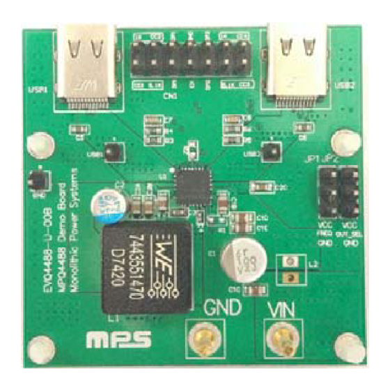
The EVQ4488-U-00B Evaluation Board is
designed to demonstrate the capabilities of
MPS' MPQ4488.The MPQ4488 integrates a
monolithic step-down switch-mode converter
with two USB current-limit switches and
charging port identification circuitry for each
port. It achieves 6A output current over a wide
input-supply range with excellent load and line
regulation.
The output of the USB switch is current limited.
Both USB ports support DCP schemes for
Battery Charging specification (BC1.2), the
Divider Mode, 1.2V/1.2V Mode and USB TYPE-
C 5V@3A DFP Mode eliminating outside user
interaction.
ELECTRICAL SPECIFICATION
Parameter
Symbol
Operating Input
Voltage
Switching
Frequency
Output Voltage
V
USB1
USB1_ I
Output Current
USB2_ I
EVQ4488-U-00B EVALUATION BOARD
(L x W x H) 5cm x 5cm x 1.7cm
(Four Layer PCB/2oz per layer)
Board Number
EVQ4488-U-00B
EVQ4488-U-00B Rev. 1.0
9/12/2017
MPS Proprietary Information. Patent Protected. Unauthorized Photocopy and Duplication Prohibited.
Value
Units
V
12
V
IN
Fs
450
kHz
/V
5.17
V
USB2
3
A
OUT
3
A
OUT
MPS IC Number
MPQ4488
www.MonolithicPower.com
© 2017 MPS. All Rights Reserved.
EVQ4488-U-00B
Smart, Dual USB Charging Port Power
Converter with Programmable Frequency
for Automotive, AEC-Q100 Qualified
FEATURES
Wide 6V to 36V Operating Input-Voltage
Range
Selectable Output Voltage: 5.1V, 5.17V and
5.3V
90mV Line Drop Compensation
Accurate USB1/USB2 Output-Current Limit
18mΩ/15mΩ Low R
Power MOSFETs
18mΩ/18mΩ
USB1/USB2 Power MOSFETs
Load Shedding versus Temperature
Hiccup Current Limit for both Buck and USB
Supports DCP schemes for BC1.2, Divider
Mode, and 1.2V/1.2V Mode
Supports USB TYPE-C 5V@3A Mode
APPLICATIONS
USB Dedicated Charging Ports (DCP)
USB Type-C Charging Port
All MPS parts are lead-free, halogen free, and adhere to the RoHS directive. For
MPS green status, please visit MPS website under Quality Assurance.
"MPS" and "The Future of Analog IC Technology" are Registered Trademarks
of Monolithic Power Systems, Inc.
100
96
92
88
84
80
0
Internal Buck
DS(ON)
Low
R
DS(ON)
1
2
3
4
5
6
Internal
7
1
Advertisement

Subscribe to Our Youtube Channel
Related Manuals for MPS EVQ4488-U-00B


Summary of Contents for MPS EVQ4488-U-00B
- Page 1 USB Type-C Charging Port Operating Input Voltage All MPS parts are lead-free, halogen free, and adhere to the RoHS directive. For MPS green status, please visit MPS website under Quality Assurance. Switching “MPS” and “The Future of Analog IC Technology” are Registered Trademarks Frequency of Monolithic Power Systems, Inc.
-
Page 2: Evaluation Board Schematic
EVQ4488-U-00B, Smart, Dual USB Charging Port Power Converter EVALUATION BOARD SCHEMATIC Note: R7 and R8 are on the bottom side of EVB board. EVQ4488-U-00B Rev. 1.0 www.MonolithicPower.com 9/12/2017 MPS Proprietary Information. Patent Protected. Unauthorized Photocopy and Duplication Prohibited. © 2017 MPS. All Rights Reserved. - Page 3 Wurth 61301421121 pins open 2.54mm, 3pin header, JP1,JP2 Header Wurth 61300311121 default all pins open EVQ4488-U-00B Rev. 1.0 www.MonolithicPower.com 9/12/2017 MPS Proprietary Information. Patent Protected. Unauthorized Photocopy and Duplication Prohibited. © 2017 MPS. All Rights Reserved.
-
Page 4: Typical Performance Characteristics
=12V, V =5.17V =12V, V =5.17V Protection USB1_V USB1_V 2V/div. 2V/div. 2V/div. 1V/div. 1V/div. USB1_I USB1_I 1A/div. 1A/div. A/div. EVQ4488-U-00B Rev. 1.0 www.MonolithicPower.com 9/12/2017 MPS Proprietary Information. Patent Protected. Unauthorized Photocopy and Duplication Prohibited. © 2017 MPS. All Rights Reserved. - Page 5 EVQ4488-U-00B, Smart, Dual USB Charging Port Power Converter TYPICAL PERFORMANCE CHARACTERISTICS (continued) = 12V, V = 5.17V, L =4.7µH, T = 25°C, unless otherwise noted. EVQ4488-U-00B Rev. 1.0 www.MonolithicPower.com 9/12/2017 MPS Proprietary Information. Patent Protected. Unauthorized Photocopy and Duplication Prohibited. © 2017 MPS. All Rights Reserved.
-
Page 6: Printed Circuit Board Layout
PRINTED CIRCUIT BOARD LAYOUT Figure 1—Top Silk Layer Figure 2—Top Layer Figure 3—Middle1 Layer Figure 4—Middle2 Layer Figure 5—Bottom Layer EVQ4488-U-00B Rev. 1.0 www.MonolithicPower.com 9/12/2017 MPS Proprietary Information. Patent Protected. Unauthorized Photocopy and Duplication Prohibited. © 2017 MPS. All Rights Reserved. - Page 7 USB2 output. Keep R4, R6 float. Remove C7 and C8. NOTICE: The information in this document is subject to change without notice. Please contact MPS for current specifications. Users should warrant and guarantee that third party Intellectual Property rights are not infringed upon when integrating MPS products into any application.
Need help?
Do you have a question about the EVQ4488-U-00B and is the answer not in the manual?
Questions and answers