Advertisement
Quick Links
The Future of Analog IC Technology
DESCRIPTION
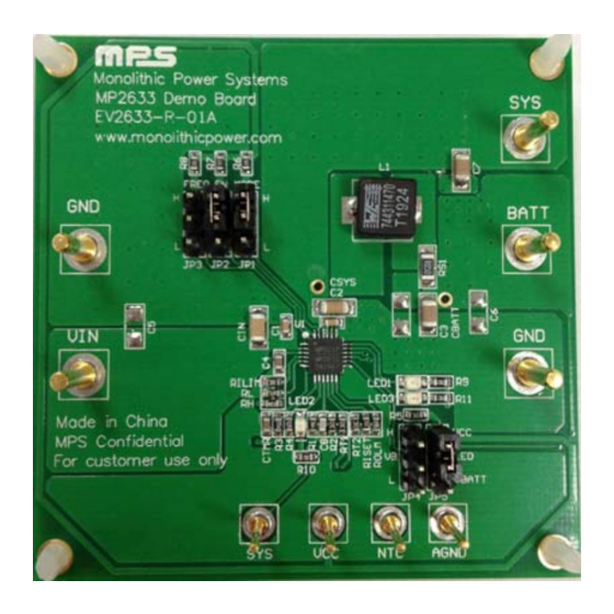
The EV2633-R-01A is the evaluation board
designed to demonstrate the capabilities of
MPS' MP2633, a highly-integrated, flexible
switch-mode battery charge management and
system power path management device for a
single-cell Li-ion and Li-Polymer battery used in
a wide range of portable applications.
EV2633 uses two operation modes -- charge
mode and boost mode -- to allow management
of system and battery power based on the state
of the input.
When input power is present, the board
charges
a
single-cell
programmable charge current of up to 1.5A.
In the absence of an input source, the board
switches to boost mode through the MODE pin
to power the SYS pins from the battery with a
current up to 1A.
The evaluation board provides full-operating-
status indication to distinguish charge mode
from boost mode.
For guaranteed safe operation, the EV2633 has
input-over-voltage
protection,
voltage protection, thermal shutdown, battery-
temperature monitoring, and programmable
timer to prevent prolonged charging of a dead
battery.
ELECTRICAL SPECIFICATION
Parameter
Symbol
Input Voltage Range
Charge Full Voltage
V
Charge Current
Input Current Limit
Battery Voltage
SYS Voltage
Regulation
SYS Output Current
Limit
EV2633-R-01A Rev.1.0
1/15/2014
MPS Proprietary Information. Patent Protected. Unauthorized Photocopy and Duplication Prohibited.
battery
with
battery
over-
Value
Units
V
4.24 – 6
V
IN
4.2/ 3.6
V
BATT_Full
I
1.5
A
CHG
I
2
A
IN_LIM
V
2.5 – 4.35
V
BATT
V
SYS
5
V
I
SYS
1
A
www.MonolithicPower.com
© 2014 MPS. All Rights Reserved.
Full Power Management IC
For Single-Cell Battery System
FEATURES
• 4.5V-to-6V Operating Input Voltage Range
• Power
Management
Input-Current
Regulation
• Up to 1.5A Programmable Charge Current
• Selectable 3.6V / 4.2V Charge Voltage with
0.5% Accuracy
• Battery Temperature Monitoring
• Full Operation Indicators
• Programmable Timer-Back-up Protection
• Battery-Reverse-Leakage Blocking
• Reverse-Boost-Operation
a
System
• Up to 91% 5V Boost Mode Efficiency @ 1A
•
Up to 1A Programmable Output Current Limit
in Boost Mode
APPLICATIONS
• Sub-battery Applications
• Power-bank Applications for Smart-Phone,
Tablet and Other Portable Devices
All MPS parts are lead-free and adhere to the RoHS directive. For MPS green
status, please visit MPS website under Products, Quality Assurance page.
"MPS" and "The Future of Analog IC Technology", are Registered Trademarks
of Monolithic Power Systems, Inc.
EV2633-R-01A
Function
Integrated
Limit
and
Input-Voltage
for
Powering
1
Advertisement

Subscribe to Our Youtube Channel
Related Manuals for MPS EV2633-R-01A


Summary of Contents for MPS EV2633-R-01A
- Page 1 All MPS parts are lead-free and adhere to the RoHS directive. For MPS green voltage protection, thermal shutdown, battery- status, please visit MPS website under Products, Quality Assurance page. temperature monitoring, and programmable “MPS” and “The Future of Analog IC Technology”, are Registered Trademarks timer to prevent prolonged charging of a dead of Monolithic Power Systems, Inc.
-
Page 2: Evaluation Board Schematic
(L × W × H) 6.1cm × 5.1cm × 1.3cm Board Number MPS IC Number EV2633-R-01A MP2633 EVALUATION BOARD SCHEMATIC EV2633-R-01A Rev.1.0 www.MonolithicPower.com 1/15/2014 MPS Proprietary Information. Patent Protected. Unauthorized Photocopy and Duplication Prohibited. © 2014 MPS. All Rights Reserved. - Page 3 95.2k 1% Film Resistor;1% RES/0603 Yageo RC0603FR-0795K2L Sense Resistor; RES/1206 Yageo RL1206FR-070R050L 1%;1/2W; JP1, JP2, JUMPER/3P/DIP/2. JP3, 54mm JP4, QFN24/4X4MM/EP MP2633GR EV2633-R-01A Rev.1.0 www.MonolithicPower.com 1/15/2014 MPS Proprietary Information. Patent Protected. Unauthorized Photocopy and Duplication Prohibited. © 2014 MPS. All Rights Reserved.
-
Page 4: Printed Circuit Board Layout
EV2633-R-01A – 1.5A SINGLE-CELL SWITCH MODE BATTERY CHARGER PRINTED CIRCUIT BOARD LAYOUT Figure 2: Top Layer Figure 1: Top Silkscreen Layer Figure 3: Bottom Layer EV2633-R-01A Rev.1.0 www.MonolithicPower.com 1/15/2014 MPS Proprietary Information. Patent Protected. Unauthorized Photocopy and Duplication Prohibited. © 2014 MPS. All Rights Reserved. - Page 5 70(kΩ) 40(mV) × (A)= (kΩ) RS1(mΩ) ISET For example, for a charge current of 1.5A, use a 37.4kΩ R ISET EV2633-R-01A Rev.1.0 www.MonolithicPower.com 1/15/2014 MPS Proprietary Information. Patent Protected. Unauthorized Photocopy and Duplication Prohibited. © 2014 MPS. All Rights Reserved.
- Page 6 600kHz by connecting the FREQ pin to “L”. For the other detailed description on the operation of the MP2633, please refer to the datasheet. EV2633-R-01A Rev.1.0 www.MonolithicPower.com 1/15/2014 MPS Proprietary Information. Patent Protected. Unauthorized Photocopy and Duplication Prohibited. © 2014 MPS. All Rights Reserved.
- Page 7 5. Remove the shunt between the “EN” and “H” to disable charging. 6. Re-insert the shunt between the “EN” and “H” to enable charging. Figure 4—Setup for Charge Mode EV2633-R-01A Rev.1.0 www.MonolithicPower.com 1/15/2014 MPS Proprietary Information. Patent Protected. Unauthorized Photocopy and Duplication Prohibited. © 2014 MPS. All Rights Reserved.
- Page 8 Figure 5—Setup for Boost Mode NOTICE: The information in this document is subject to change without notice. Please contact MPS for current specifications. Users should warrant and guarantee that third party Intellectual Property rights are not infringed upon when integrating MPS products into any application.
Need help?
Do you have a question about the EV2633-R-01A and is the answer not in the manual?
Questions and answers