Table of Contents
Advertisement
RESISTRON
RES-5007
Operating
Instructions
Important features
•
Automatic zeroing (AUTOCAL)
•
Automatic optimisation (AUTOTUNE)
•
Automatic configuration of the secondary voltage and current range (AUTORANGE)
•
Automatic phase correction (AUTOCOMP)
•
Automatic frequency adaptation
•
Analogue input for setpoint specification with potentiometer or 0...10 VDC
•
Analogue output 0...10 VDC for ACTUAL temperature
•
24 VDC control signals for START, AUTOCAL and RESET
•
Alarm function with error diagnosis
•
Heating element alloy and temperature range can be selected
•
Micro-USB interface for ROPEXvisual
•
cULus approval
ROPEX Industrie-Elektronik GmbH
Adolf-Heim-Str. 4
74321 Bietigheim-Bissingen (Germany)
®
Tel.: +49 (0)7142-7776-0
Fax: +49 (0)7142-7776-211
E-Mail:
info@ropex.de
Internet:
https://ropex.de
Data subject to change
Advertisement
Table of Contents

Related Manuals for Ropex RESISTRON RES-5007


Summary of Contents for Ropex RESISTRON RES-5007
- Page 1 Alarm function with error diagnosis • Heating element alloy and temperature range can be selected ® • Micro-USB interface for ROPEXvisual • cULus approval ROPEX Industrie-Elektronik GmbH Tel.: +49 (0)7142-7776-0 E-Mail: info@ropex.de Adolf-Heim-Str. 4 Fax: +49 (0)7142-7776-211 Internet: https://ropex.de 74321 Bietigheim-Bissingen (Germany)
-
Page 2: Table Of Contents
Contents Revision list ......3 Device functions ....18 Display and operating elements . -
Page 3: Revision List
Revision list Revision list Version Change • Creation of documentation General information ® This RESISTRON temperature controller is manufactured according to EN 61010-1. In the course of its manu- facture it passed through quality assurance, whereby it was subjected to extensive inspections and tests. As a result of this, the product left our factory in perfect condition. -
Page 4: Impulse Transformer
The use of an original ROPEX line filter is mandatory in order to comply with the standards and provisions mentioned in section 2.7 "Standards / CE marking" on page 4. This device must be installed and connected according to the instructions contained in section "Power supply"... -
Page 5: Maintenance
Compliance with these standards and provisions is only guaranteed if original accessories and / or peripheral components approved by ROPEX are used. If not, then the equipment is operated on the user's own responsibility. The CE marking on the controller confirms that the device itself complies with the above-mentioned standards. -
Page 6: Use
Careless, uncontrolled disposal can cause damage to the environment and human health. By ensuring that your product is disposed of or recycled in a responsible way, you can help protect the environment and human health. This device must not be disposed of as residual waste! ®... -
Page 7: Controller Features
3. Wiring of the system in accordance with the regulations in section 6.3 "Power supply" on page 10, section 6.6 "Supply voltage" on page 13 and the ROPEX Application Report. The specifications in section 6.2 "Installation notes" on page 9 must also be observed. - Page 8 If this overcurrent protective device is not sufficient for the sealing application, two separate overcurrent pro- tective devices must be provided for the controller and the sealing application ( ROPEX application report). The overcurrent protective device must be located in the immediate vicinity of the device.
-
Page 9: Installation Notes
Mounting and Installation Installation notes Sample depiction Use heatseal bands with suitable temperature coefficient Heatseal element push-on with coppered ends connectors Heatsealing band R= f (T) No additional Connect U measuring resistance wires directly to in secondary heatsealing band ends Note circuit number... -
Page 10: Power Supply
Connect core to ground. Use transformers with a one section bobbin. The power, duty cycle and voltage values must be deter- mined individually according to the application ( ROPEX SEC. Application Report and "Accessories" leaflet for impulse transformers). -
Page 11: Line Filter
ROPEX line filters are specially optimized for use in RESISTRON control loops. Providing that they are installed and wired correctly, they guarantee compliance with the EMC limit values. You can find the exact specification of the line filter in the ROPEX Application Report calculated for your particular heatsealing application. - Page 12 Mounting and Installation 6.5.1 PEX-W4 terminal wires terminal block Snap-on for DIN-rail 35 x 7.5 mm or 35 x 15 mm (DIN EN 50022) 6.5.2 PEX-W5 Mounting on DIN-rail 35 x 7.5 mm or 35 x 15 mm (DIN EN 50022). Page 12 RES-5007 Version 1...
-
Page 13: Supply Voltage
Mounting and Installation Supply voltage To provide power to the RES-5007, voltage of 24 VDC must be applied to the terminals 12+13. The maximum cur- rent draw is 1.0 A. The supply voltage input is protected against faulty polarisation. Connection diagram (standard) Line f ilte RES-5007... -
Page 14: Commissioning And Operation
( see section 8.16 "Error messages" on page 29). For secondary currents I less than 30 A, the secondary high-current line must be guided 2 times (or several times) through the transformer PEX-W4 or PEX-W5 ( ROPEX application report). Page 14 RES-5007... -
Page 15: Changing And Burning In The Heating Element
0 = Factory settings This configuration is available as standard. When the switch position “9” is selected, additional temperature ranges and alloys can be set through the ROPEX ® visualisation software ( see section 8.11 "USB interface for visualisation software ROPEXvisual "... -
Page 16: Commissioning Rules
Proceed as follows when starting up the controller for the first time: 1. Switch off network voltage; verify that no voltage is present. 2. Set the coding switch on the device in accordance with the ROPEX application report and the heating element used (section 7.2 "Device configuration" on page 14). - Page 17 If zeroing was not performed correctly, the red “ALARM” LED flashes slowly (1 Hz). Then configuration of the controller is not correct ( section 7.2 "Device configuration" on page 14, ROPEX application report). After device configuration is correct, perform zeroing again.
-
Page 18: Device Functions
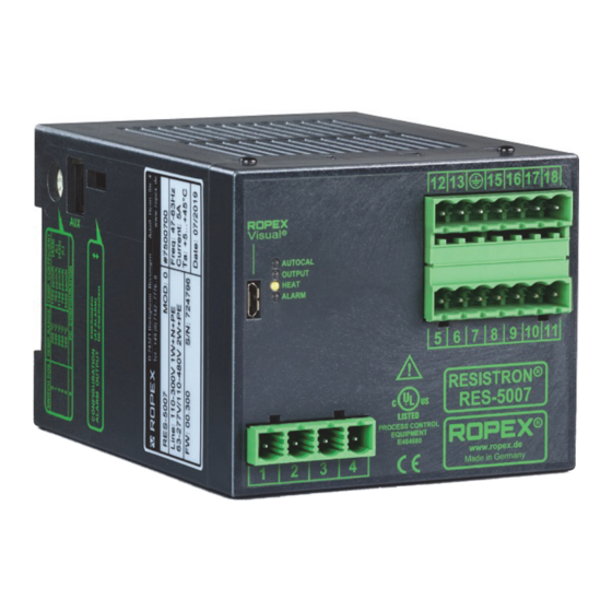
RES-5007 PROCESS CONTROL EQUIPMENT E464680 www. ROPEX Made in Germany The LEDs display additional operating statuses of the controller besides the functions in the above illustration. These are shown in detail in the following table: Flashes slowly (1 Hz) Flashes quickly (4 Hz) -
Page 19: Temperature Setting (Setpoint Specification)
The connection line between controller and potentiometer must be screened. When the ROPEX precision potentiometer PD-x (PD-03 for 300 °C or PD-05 for 500 °C) is used, the set SET- POINT temperature can be set exactly with the help of the numbers in the viewing window of the fine drive button. -
Page 20: Temperature Display
A display instrument can be attached to this output for visualisation of the heating element temperature. The ROPEX temperature display ATR-x in its overall characteristics (size, scaling, dynamic behaviour) is optimally suited for this use and can be used for this, if needed ( section 13 "How to order" on page 38). -
Page 21: Autom. Zeroing (Autocal)
Device functions Beyond that, malfunctions in the control circuit (loose connections, contacting and wiring problems) and possibly network faults can be observed very well at the display instrument and interpreted accordingly. This applies also for mutual influencing of several neighbouring control circuits. In case of alarm, this analogue output is used to output differentiated error messages (... -
Page 22: Start Signal (Heat)
Device functions early, the function is blocked. 2. The AUTOCAL function is not executed when the cooling speed of the heating element is more than 0.1 K/s. With an activated control signal, the function is automatically carried out if the cooling speed has fallen below the above-named value. -
Page 23: Measurement Impulse Duration
Measurement impulse duration The length of the measurement impulses generated by the controller can be set with this parameter. For certain applications, it can be necessary to lengthen the measurement impulse beyond the standard of 1.7 ms ( ROPEX application report). -
Page 24: 24 Vdc
Device functions AUTOCAL- <2.0 s Signal 24 VDC Function AUTOCOMP AUTOCAL “AUTOCAL” Lights up “OUTPUT” Lights up During execution of the AUTOCOMP function, the “OUTPUT” LED flashes several times and the actual value output (terminal 17+13) goes to 0…3 °C (i.e. approx. 0 VDC). 3. -
Page 25: Temperature Diagnosis
During execution of the AUTOCOMP function, the “OUTPUT” LED flashes several times and the actual value output (terminal 17+13) goes to 0…3 °C (i.e. approx. 0 VDC). Temperature diagnosis An additional temperature diagnosis can be activated with the ROPEX visualisation software ( section 8.11 ® "USB interface for visualisation software ROPEXvisual "... -
Page 26: Is Activeheat-Up Time Monitoring
309, 310 is output and the alarm relay switches on. A delay time (0...9.9 s.) can also be set with the ROPEX visualisation software. After the lower tolerance band limit is exceeded, the temperature diagnosis takes place only after the parameterised delay time has expired. As a result, the temperature diagnosis can be intentionally suppressed, such as during a temperature drop caused by closing the welding jaws. -
Page 27: Usb Interface For Visualisation Software Ropexvisual
AUTOCAL processes. The last 400 messages are stored. These can be read and displayed with the ROPEX visualisation software. The RES-5007 also has an integrated clock ( section 8.14 "Integrated clock (date and time)" on page 27). The messages are then stored with the date and time specified (time stamp). -
Page 28: System Monitoring/Alarm Output
2…4 weeks. If the controller is switched off longer, the date and time must be set again. This must be done with the ROPEX visualisation soft- ®... -
Page 29: Error Messages
The described error numbers can be displayed with the ® ROPEX visualisation software ( section 8.11 "USB interface for visualisation software ROPEXvisual " on page 27). The error search can thus be performed even more effectively. -
Page 30: Actual Value
Device functions Part 1 of 3: Error messages (malfunctions) NOTE: The specified error messages are output as malfunctions (actual value output emits constant error voltage; alarm LED is continuously lit; alarm relay is active). Actual value Measure of machine in Error Measure if initial start- output... - Page 31 Device functions Part 2 of 3: Error messages (warnings) NOTE: The specified error messages are first output as warnings (actual value output switches between two values; alarm LED flashes; alarm output is not active). After activation of the START signal, it is output as a malfunction (actual value output no longer changes, see bold-italic values;...
- Page 32 Device functions Part 3 of 3: Error messages (warnings) NOTE: The specified error messages are first output as warnings (actual value output switches between two values; alarm LED flashes; alarm output is not active). After activation of the START signal, it is output as a malfunction (actual value output no longer changes, see bold-italic values;...
-
Page 33: Error Ranges And Causes
Device functions 8.17 Error ranges and causes Temperature controller HARDWARE Explanations of the possible error causes can be taken from the following table. Malfunc- Explanations Possible causes tion range Interruption of the load circuit after - Wire break, heating element break the U pickup point - Contacting at the heating element defective... -
Page 34: Factory Settings
Alarm output active in case of alarm Alarm output Automatic AUTOCOMP: OFF Phase correction (AUTOCOMP) Measurement impulse Measurement impulse duration: 1.7 ms duration Temperature Temperature diagnosis: OFF diagnosis Heat-up time Heat-up time monitoring: OFF monitoring [X] Only with ROPEX visualisation software Page 34 RES-5007 Version 1... -
Page 35: Technical Data
Besides setting through the rotary encoder switch (see below), the setting for the and temperature temperature range and temperature coefficient can be performed through the range ROPEX visualisation software ( section 8.11 "USB interface for visualisation ® software ROPEXvisual " on page 27): Temperature range: 200 °C, 300 °C, 400 °C or 500 °C... -
Page 36: = 30 Vdc
Technical data Analogue output 0…10 VDC, I = 5 mA, electrically separated from the heating circuit (Actual value) corresponding to 0…300 °C or 0…500 °C Terminal 17+13 Precision: ±1% plus 50 mV Reference voltage +10 VDC / ±5%, I = 5 mA output Digital logic level LOW (0 V): 0…2 VDC... -
Page 37: Dimensions
Dimensions Dimensions 75,0 90,0 Modifications (MODs) ® The RESISTRON temperature controller RES-5007 is suitable for very many welding applications due to its uni- versal design. ® A device modification (MOD) is available for the RESISTRON temperature controller RES-5007 to implement special applications. -
Page 38: How To Order
50520: Continuous curr. 50 A, 520 VAC, art. no. 885509 (with UL and CSA certification) Impulse transformer For design and order specifications, see ROPEX applica- tion report Design in accordance with EN 61558 Available with UL certifications and thermal switch, if nec- essary. - Page 39 How to order Temperature display ATR- . 3: 300 °C range, art. no. 882130 5: 500 °C range, art. no. 882150 Lines For design and order specifications, see ROPEX applica- tion report Additional accessories “Accessories” brochure Version 1 RES-5007...
-
Page 40: Index
Index Index Numbers Functional principle Fuse 24VDC supply HEAT Actual value output Heating element type Alarm output Heat-up time monitoring Alarm relay High altitude Alloy How to order Ambient conditions Humidity Ambient temperature Analogue input Analogue output Impulse transformer Application Report Installation AUTOCAL Installation rules... - Page 41 Index Thermal impulse process Time Setpoint potentiometer Time stamp Setpoint specification Transformer Setup stipulations Transportation START signal System diagnosis System monitoring UL file USB interface Technical data Temperature coefficient Temperature diagnosis Visualisation software Temperature display Temperature range Temperature regulation Wiring Temperature setting Page 41 RES-5007...
Need help?
Do you have a question about the RESISTRON RES-5007 and is the answer not in the manual?
Questions and answers