Table of Contents
Advertisement
Quick Links
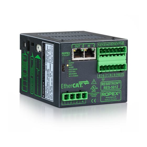
RESISTRON
RES-5012
Operating
instructions
Important features
•
Complete control via EtherCAT
•
Automatic zeroing (AUTOCAL)
•
Automatic optimisation (AUTOTUNE)
•
Automatic configuration of the secondary voltage and current range (AUTORANGE)
•
Automatic phase correction (AUTOCOMP)
•
Automatic frequency adaptation
•
Booster output
•
Analogue output 0...10 VDC for ACTUAL temperature
•
Alarm function with error diagnosis
•
Heating element alloy and temperature range can be selected
•
Wide voltage range for the use of 110...415 V
•
Eight channels for administration of various calibration values
•
Micro-USB interface for ROPEXvisual
•
cULus approval
1. EtherCAT
tion GmbH, Germany.
ROPEX Industrie-Elektronik GmbH
Adolf-Heim-Str. 4
74321 Bietigheim-Bissingen (Germany)
®
interface
is a registered trademark and patented technology, licensed by Beckhoff Automa-
®
Tel.: +49 (0)7142-7776-0
Fax: +49 (0)7142-7776-211
1
(2 x RJ-45)
®
E-Mail:
info@ropex.de
Internet:
https://ropex.de
Data subject to change
Advertisement
Table of Contents

Related Manuals for Ropex RESISTRON RES-5012


Summary of Contents for Ropex RESISTRON RES-5012
- Page 1 • Micro-USB interface for ROPEXvisual • cULus approval 1. EtherCAT is a registered trademark and patented technology, licensed by Beckhoff Automa- ® tion GmbH, Germany. ROPEX Industrie-Elektronik GmbH Tel.: +49 (0)7142-7776-0 E-Mail: info@ropex.de Adolf-Heim-Str. 4 Fax: +49 (0)7142-7776-211 Internet: https://ropex.de...
-
Page 2: Table Of Contents
Contents Revision list ......3 Device functions ....21 LEDs and controls . -
Page 3: Revision List
® The RESISTRON temperature controller must be set and coded according to the temperature coefficient of the heatsealing band. The temperature coefficient must be taken from the ROPEX application report and must be set accordingly. Version 2 RES-5012 Page 3... -
Page 4: Impulse Transformer
The use of an original ROPEX line filter is mandatory in order to comply with the directives mentioned in section "DECLARATION OF CONFORMITY" on page 6. This device must be installed and connected according to the instructions contained in section "Power supply"... -
Page 5: Transportation
General information Transportation Store and transport the device in its original carton. After transport, perform a visual inspection for possible damage. Disposal This device is subject to Directive 2012/19/EU concerning the reduction of the increasing amount of waste electrical and electronic equipment and the disposal of such waste in an environmentally sound way. - Page 6 We also wish to point out that the transformer which is used must be designed in accordance with VDE 0551/EN 61558 or UL 5058 for safety reasons. July 12, 2020 J. Kühner (CEO) ROPEX Industrie-Elektronik GmbH Adolf-Heim-Str. 4 74321 Bietigheim-Bissingen (Germany) Page 6...
-
Page 7: Use
® This RESISTRON temperature controller is part of the “Series 5000”, whose main characteristic is micropro- ® cessor technology. All RESISTRON temperature controllers provide temperature regulation of heating elements as are used in a variety of foil sealing processes. The most common heating elements include: •... -
Page 8: Mounting And Installation
Mounting and installation The ACTUAL temperature of the heating element is output through the EtherCAT ® interface and through an ana- logue output 0…10 VDC. The real heating element temperature can be visualised on an external display instru- ment (e.g. ATR-x) or via the operating unit of the machine controller. The RES-5012 has an integrated error diagnosis that checks both the external system (heating element, wiring, etc.) and the internal electronics. - Page 9 If one such device is not adequate for the heatsealing application, two separate overcurrent protective devices should be provided – one for the controller and one for the application ( ROPEX Application Report). The overcurrent protective device must be located directly adjacent to the controller.
-
Page 10: Installation Steps
Mounting and installation Installation steps Sample depiction Use heatseal bands with suitable temperature coefficient Heatseal element push-on with coppered ends connectors Heatsealing band R= f (T) No additional Connect U measuring resistance wires directly to in secondary heatsealing band ends Note circuit number... -
Page 11: Power Supply
Connect core to ground. Use transformers with a one section bobbin. The power, duty cycle and voltage values must be deter- mined individually according to the application ( ROPEX SEC. Application Report and "Accessories" leaflet for impulse transformers). -
Page 12: Line Filter
ROPEX line filters are specially optimized for use in RESISTRON control loops. Providing that they are installed and wired correctly, they guarantee compliance with the EMC limit values. You can find the exact specification of the line filter in the ROPEX Application Report calculated for your particular heatsealing application. - Page 13 Mounting and installation 6.5.1 PEX-W4 terminal wires terminal block Snap-on for DIN-rail 35 x 7.5 mm or 35 x 15 mm (DIN EN 50022) 6.5.2 PEX-W5 Mounting on DIN-rail 35 x 7.5 mm or 35 x 15 mm (DIN EN 50022). Version 2 RES-5012 Page 13...
-
Page 14: Wiring Diagram (Standard)
Mounting and installation Wiring diagram (standard) Line filter RES-5012 LINE Ethernet PORT 1 (RJ45) BOOSTER OUTPUT Ethernet module prim. Shield Impulse Ethernet transformer PORT 2 (RJ45) (for assignment sec. see PORT 1) Ground Heat- Must be grounded sealing externally to band prevent twisted... -
Page 15: Wiring Diagram With Booster Connection
Mounting and installation Wiring diagram with booster connection Line filter RES-5012 LINE Ethernet PORT 1 (RJ45) Booster twisted Ethernet Max. length 1 m module prim. Shield Impulse Ethernet transformer PORT 2 (RJ45) (for assignment sec. see PORT 1) Ground Heat- Must be grounded sealing externally to... -
Page 16: Startup And Operation
( section 8.19 "Error messages" on page 50). If the secondary current I is less than 30 A, the secondary high-current wire must be laid twice (or several times) through the PEX-W4, or PEX-W5 current transformer ( ROPEX Application Report). Page 16 RES-5012... -
Page 17: Band
The setting of the rotary coding switch for the temperature range and alloy can be overwritten with the parameter data ( section 8.7 "Object dictionary" on page 30). If the switch is set to "9", more temperature ranges and alloys can be selected in the ROPEX visualization software ®... - Page 18 (factory setting) If the switch is set to "Alarm relay de-energized at alarm / PC CONFIGURATION", you can select more alarm output configurations in the ROPEX visualization software ( section 8.12 "USB interface for visualization soft- ® ware ROPEXvisual "...
-
Page 19: Startup Procedure
Startup and operation Each time the heatsealing band is replaced, you must calibrate the zero point with the AUTOCAL function while the band (and the environment, i.e. silicone, PTFE cover, sealing bar etc.) is still cold in order to compensate pro- duction-related resistance tolerances. - Page 20 (1 Hz). In this case the controller configuration is incorrect ( section 7.2 "Device configuration" on page 16, ROPEX Application Report). Repeat the calibration after correcting the controller configuration. 9. After the zero point has been successfully calibrated, specify a defined temperature by means of the EtherCAT ®...
-
Page 21: Device Functions
E QUI P M E NT 24V POWER Lit if external 24VDC power E 464680 www. ROPEX (green LED) supply is present. Made in Germany In addition to the functions shown above, the LEDs also indicate various controller operating states. These states... - Page 22 Device functions Blinks slowly (1 Hz) Blinks fast (4 Hz) Lit continuously START requested but func- tion blocked (e.g. HEAT — START executing (yellow) AUTOCAL active, set tem- perature < 40 °C) OUTPUT In control mode, luminous intensity is proportional to heating current. (green) Configuration error, no Controller calibrated incor-...
-
Page 23: Ethercat ® Communication
The ESI file ROPEX RES-5012 UPT-6012 V1.2.xml of the RES-5012 contains all essential controller information for the con- figuration, e.g. the I/O data description, parameter descriptions, error messages etc. The ESI file can be requested by e-mail (support@ropex.de) or downloaded from our website (https://ropex.de). -
Page 24: Communication Protocol
Device functions Communication protocol The communication protocol consists of 2x16 bit input words and 3x16 bit output words (from the point of view of the controller). This protocol separates the set point and the actual value of the RES-5012 from the status infor- mation and the control functions, to simplify decoding by the EtherCAT ®... - Page 25 Device functions 8.5.1 Automatic zero calibration AUTOCAL (AC) Owing to the automatic zero calibration (AUTOCAL) function, there is no need to adjust the zero point manually on the controller. This function adjusts the controller to the current and voltage signals present in the system and calibrates it to the value which is predefined in the parameter data (...
- Page 26 Device functions 8.5.3 Reset (RS) This bit resets the controller if the controller shows a fault. No AUTOCAL or START requests are accepted as long as the RS bit is set. Until it is reset again, only error codes 201…203, 901, 913 are evaluated and output by the error diagnosis function. The power unit is not activated in this state and no measuring impulses are generated.
-
Page 27: Output Data
Device functions If the application does not require any format changes, the channel can remain set to 0. In this case, the tempera- ture controller behaves in exactly the same way as older models where different calibration data records are not supported. - Page 28 Device functions is outside of the tolerance band, the TO bit is reset (see graph below). Actual value Set+ Δϑ high Set+ Δϑ Time TO bit Time Unlike the "Temperature achieved" status bit (TE bit), the actual temperature is evaluated independently of the control mode.
- Page 29 Device functions 8.6.9 Standby active (SA) This bit is active if the RS bit is set. It shows the PLC when the controller has accepted the RS bit or the MP bit, so that these bits can be reset again (handshake). 8.6.10 Measurement interruption (MU) This bit is available as from firmware version 303.
-
Page 30: Object Dictionary
Device functions Object dictionary Index: Acces Data Name Range Default value type index 1000 Device Type UINT32 1001 Error Register 0…255 UINT8 1008 Manufacturer Device Name RES-5012 STRING UINT8 100A Manufacturer Software Version UINT32 1018:00 Identity Object UINT8 1018:01 Vendor ID 0x00000576 UINT32 1018:02... - Page 31 Device functions Index: Acces Data Name Range Default value type index 1A00:05 SubIndex 005 0x30000501 UINT32 1A00:06 SubIndex 006 0x30000601 UINT32 1A00:07 SubIndex 007 0x30000701 UINT32 1A00:08 SubIndex 008 0x30000801 UINT32 1A00:09 SubIndex 009 0x30000901 UINT32 1A00:0A SubIndex 010 0x30000A01 UINT32 1A00:0B SubIndex 011...
- Page 32 Device functions Index: Acces Data Name Range Default value type index 2000:09 Reserved_2 BIT5 3000:00 Inputs UINT8 3000:01 Actual temperature -99…999 INT16 3000:02 0 (off), 1 (on) BOOL 3000:03 0 (off), 1 (on) BOOL 3000:04 0 (off), 1 (on) BOOL 3000:05 0 (off), 1 (on) BOOL...
- Page 33 Device functions Index: Acces Data Name Range Default value type index 4005 Diagnosis off (0), on (1) UINT8 4006 Measurement impulse duration 17…30 UINT8 (1.7…3.0 ms) 4007 Data format Little Endian Little Endian (Intel) UINT8 (Intel) (0), Big Endian (Moto- rola) (1) 400A:00 Temperature coefficient...
- Page 34 Device functions Index: Acces Data Name Range Default value type index 4302 Operating hours 0…999999999 UINT32 (0…99999999.9h) 4303 Total cycle counter 0…999999999 UINT32 4304 Total cycle counter, clearable 0…999999999 UINT32 4305:00 Cycle counter per channel, clearable UINT8 4305:01 SubIndex 001 0…999999999 UINT32 4305:02...
- Page 35 Device functions Index: Acces Data Name Range Default value type index 4308:03 SubIndex 003 0…65535 UINT16 (0…6553.5mΩ) 4308:04 SubIndex 004 0…65535 UINT16 (0…6553.5mΩ) 4308:05 SubIndex 005 0…65535 UINT16 (0…6553.5mΩ) 4308:06 SubIndex 006 0…65535 UINT16 (0…6553.5mΩ) 4308:07 SubIndex 007 0…65535 UINT16 (0…6553.5mΩ) 4308:08 SubIndex 008...
- Page 36 Device functions 8.7.1 Temperature range and alloy This parameter determines both the temperature range and the heatsealing band alloy. You can overwrite the set- ting of the rotary coding switch ( section 7.2.2 "Configuration of the rotary coding switch for the temperature range and alloy"...
- Page 37 It may be necessary to compensate the phase angle displacement between the U and I measuring signals for specific heatsealing applications ( ROPEX Application Report). The AUTOCOMP function is provided for this purpose. The following settings are possible: 1. "Off" (factory setting) The AUTOCOMP function is switched off.
- Page 38 Device functions AC bit <2.0 s Function AUTOCOMP AUTOCAL "AUTOCAL" "OUTPUT" The "OUTPUT" LED blinks several times when the AUTOCOMP function is executed and the actual value output (terminals 17+18) changes to 0…3 °C (corresponds to approx. 0 VDC). 3. "AUTO" This setting causes the AUTOCOMP function to be automatically activated after the AUTOCAL function has been successfully executed.
- Page 39 Device functions AC bit Function AUTOCOMP AUTOCAL "AUTOCAL" "OUTPUT" The "OUTPUT" LED blinks several times when the AUTOCOMP function is executed and the actual value output (terminals 17+18) changes to 0…3 °C (corresponds to approx. 0 VDC). The AUTOCOMP function must be activated in the parameter data ( section 8.7 "Object dictionary" on page 30) (default setting: AUTOCOMP off).
- Page 40 The high and low tolerance limits cannot be set in the ROPEX visualization software. The same limits apply as with the TO bit. They can only be set in the parameter data ( section 8.7 "Object dictionary" on page 30).
- Page 41 ROPEX visualization software. It has no effect on the ACTUAL temperature that appears at the controller’s analog output or is plotted in the graphics window of the ROPEX visualization software. The various hold modes are shown below:...
-
Page 42: Integrated Web Server
You can go direct to the official ROPEX website by clicking on the ROPEX logo in the top right-hand corner. The web server uses JavaScript and has been successfully tested with Internet Explorer 9, 10, and 11 as well as with Microsoft Edge. - Page 43 Device functions The inputs ( section 8.5 "Input data" on page 24) are shown in the left-hand column, the outputs ( section 8.6 "Output data" on page 27) in the middle column, and the current status of all device LEDs ( section 8.1 "LEDs and controls"...
- Page 44 Device functions described in detail in section 8.19 "Error messages" on page 50. Each error code is explained in a tooltip when you hover over it briefly. The data can also be exported to a CSV file to enable further processing in another software program. By clicking on the appropriate button you can select a comma separated format or a semicolon separated format.
-
Page 45: Undervoltage Detection
Device functions 8.8.6 Calibration page This page is first available as from firmware version 303. The temperature controller stores the absolute calibration resistance of each channel (Calibration resistance ch. 0…7) with an resolution of 0.1 mΩ. The calculation of the respective calibration resistance is done at the end of the AUTOCAL function (... -
Page 46: Temperature Meter (Actual Value Output)
Device functions Trouble-free operation of the controller is only guaranteed within the specified tolerance range of the input voltage. An external voltage monitor must be connected to prevent low line or 24 VDC supply voltage from resulting in defective heatseals. 8.10 Temperature meter (actual value output) The RES-5012 supplies an analog 0…10 VDC signal, which is proportional to the real ACTUAL temperature, at... -
Page 47: Booster Connection
An indicating instrument can be connected to this output in order to visualize the temperature of the heatsealing band. The ROPEX ATR-x temperature meter is optimally adapted to this application in every respect (size, scale, dynamic behavior) and can be used for this, if needed ( section 6 "Mounting and installation" on page 8). -
Page 48: Usb Interface For Visualization Software Ropexvisual
The number of heatsealing cycles executed since the controller was shipped is stored in the internal memory (ST bit = 1). This is a read-only counter which cannot be reset. It can be displayed in the ROPEX visualization soft- ®... -
Page 49: Data Memory For Error Messages And Autocal
AUTOCAL" on page 49) together with their date and time of occurrence (timestamp). Error messages can thus be interpreted more accurately whenever a problem needs to be analyzed. The built-in clock can be set and read out in the ROPEX visualization software ( section 8.12 "USB interface for ®... -
Page 50: Error Messages
If a ROPEX temperature meter (e.g. an ATR-x) is connected to the controller’s analog output, the temperature indication can be directly assigned to the error codes if an alarm is signaled. - Page 51 Device functions If the actual value output is evaluated in order to identify an error message – in the higher-level con- troller, for instance – the tolerance window must be adjusted to prevent incorrect interpretations. Please note the tolerances of the actual value output ( section 10 "Technical data" on page 57). Version 2 RES-5012 Page 51...
- Page 52 Device functions Part 1 of 3: Error messages (faults) NOTE: The error messages shown here are output as faults (constant error voltage at actual value output, alarm LED lit continuously, alarm relay energized). Act. val. Action if machine Error output Action if machine Cause already operated, HS...
- Page 53 Device functions Part 2 of 3: Error messages (warnings) NOTE: The specified error messages are initially output as warnings (actual value output jumps back and forth between two values, alarm LED blinks, alarm relay de-energized). When the START signal is activated, the warning changes to a fault (actual value output no longer jumps back and forth, see bold italic values, alarm LED lit continuously, alarm relay energized).
- Page 54 Device functions Part 3 of 3: Error messages (warnings) NOTE: The specified error messages are initially output as warnings (actual value output jumps back and forth between two values, alarm LED blinks, alarm relay de-energized). When the START signal is activated, the warning changes to a fault (actual value output no longer jumps back and forth, see bold italic values, alarm LED lit continuously, alarm relay energized).
-
Page 55: Fault Areas And Causes
Device functions 8.20 Fault areas and causes Temperature controller HARDWARE The table below explains the possible fault causes. Fault area Explanation Possible causes Load circuit interrupted after U - Wire break, heatsealing band break - Contact to heatsealing band is defective pickoff point ... - Page 56 Device functions Fault area Explanation Possible causes - Hardware fault (replace controller) Internal device fault / no line - Jumper for alarm relay not connected or incorrectly con- voltage nected - No line voltage Page 56 RES-5012 Version 2...
-
Page 57: Factory Settings
Factory settings Factory settings ® The RESISTRON temperature controller RES-5012 is configured at the factory as follows: Rotary coding switch Heatsealing band alloy: Alloy A20 Temperature range: 300 °C heatsealing band alloy Rotary coding switch: "0" position temperature range Slide switch Alarm relay energized at alarm alarm relay Automatic phase... - Page 58 Addressing: automatic by means of topology or rotary coding switch Heatsealing band The temperature range and temperature coefficient settings can also be specified type and temperature in the ROPEX visualization software ( section 8.12 "USB interface for visualiza- ® range tion software ROPEXvisual "...
- Page 59 Technical data Alarm relay = 30 V (DC/AC), I = 0.2 A, changeover contact, potential-free Terminals 12, 13, 14 Power loss Max. 20 W Ambient conditions Max. altitude: 2000 m Ambient temperature: +5…+45 °C Max. relative humidity: 80% at temperatures up to +31 °C, decreasing linearly to 50% relative humidity at +45 °C Degree of protection IP20...
-
Page 60: Dimensions
Dimensions Dimensions 75.0 90.0 Modifications 12.1 Modifications (MODs) ® Owing to its universal design, the RESISTRON temperature controller RES-5012 is suitable for a very wide range of heatsealing applications. ® One modification (MOD) is available for the RESISTRON temperature controller RES-5012 for implementing special applications. -
Page 61: How To Order
50520: Continuous curr. 50 A, 520 VAC, art. no. 885509 (with UL and CSA certification) Impulse transformer For design and order specifications, see ROPEX applica- tion report Design in accordance with EN 61558 Available with UL certifications and thermal switch, if nec- essary. - Page 62 Booster B- . . . 075415: Impulse loaded 75 A, 415 VAC, art. no. 885302 100400: Impulse loaded 100 A, 400 VAC, art. no. 885304 Lines For design and order specifications, see ROPEX applica- tion report Page 62 RES-5012 Version 2...
-
Page 63: Index
Index Index Numbers 24VDC supply voltage Factory settings Fault Fault areas Fuse AA bit Actual value Actual value output AC bit Heatsealing band type AG bit Heatup timeout Alarm output Alarm relay Alloy Impulse transformer Altitude Input data AL bit Installation Ambient conditions Installation procedure... - Page 64 Index TE bit Thermal impulse process RA bit Time Relative humidity Timestamp Replacement (heatsealing band) TO bit Reset Transformer ROPEXvisual Transportation RS bit Type of construction Set point UL file Standby mode Undervoltage detection Start USB interface Startup ST bit System diagnosis System monitoring View of the device...
Need help?
Do you have a question about the RESISTRON RES-5012 and is the answer not in the manual?
Questions and answers