Table of Contents
Advertisement
Advertisement
Table of Contents
Troubleshooting

Subscribe to Our Youtube Channel
Related Manuals for Ultrasonix Sonix MDP


Summary of Contents for Ultrasonix Sonix MDP
- Page 1 SONIX MDP ULTRASOUND SYSTEM SERVICE MANUAL...
- Page 3 130 – 4311 Viking Way Richmond, BC V6V 2K9 Canada www.ultrasonix.com 1.866.437.9508 © 2008 Ultrasonix Medical Corporation 00.053.009, Revision A, August 29, 2008 All rights Reserved. Printed in Canada US Patents 6,911,008 – 6,558,326 – 6,325,759 SONIX MDP Service Manual 00.053.009, Revision A...
-
Page 5: Table Of Contents
3.3.10 Peripherals ..............................32 3.3.11 Voltage Configuration ............................. 33 3.3.12 Changing Fuses ............................. 35 3.3.13 System Case Connectivity Panel........................36 3.3.14 Back Connectivity Panel..........................39 3.3.15 Front Console Connectivity ..........................39 SONIX MDP Service Manual 00.053.009, Revision A Table of Contents... - Page 6 Opening the Front Block (With or Without Removing the Modulo)..............90 7.2.3 Removing the Front Block..........................91 7.2.4 Reinstalling the Front Block ..........................92 7.2.5 Closing the Front Block (With or Without Removing the Modulo) ..............94 7.2.6 Replacing the ECG Module ..........................95 Table of Contents 00.053.009, Revision A SONIX MDP Service Manual...
- Page 7 Dialup Communication Test......................135 REMOTE SUPPORT ..............................136 CHAPTER 10: LICENSE.KEY IMPORTATION ......................137 10.1 RE-IMPORT LICENSE.KEY FROM AN EXTERNAL SOURCE ................137 10.2 RE-IMPORT LICENSE.KEY FROM A LOCAL DRIVE....................138 SONIX MDP Service Manual 00.053.009, Revision A Table of Contents...
- Page 8 REGEDIT ..................................158 12.7 LCD DISPLAY IS BLANK, TOUCH SCREEN DISPLAYS CORRECTLY ..............158 12.8 LCD DISPLAY BLANK, TOUCH SCREEN DISPLAYS ULTRASONIX LOGO ONLY ..........158 12.9 LCD DISPLAY WORKS, BUT TOUCH SCREEN STILL DISPLAYS ULTRASONIX LOGO EVEN IN IMAGING MODE ............................158 12.10 SONIX DOES NOT BOOT, ERROR IS DISPLAYED ON THE LCD DISPLAY ............159 12.11 SYSTEM FREEZES DURING USE ..........................159...
- Page 9 A.5.1 Reset LCD Display to Factory Defaults ......................166 A.5.2 Create a Temporary Video Connection/Restore LCD Display with Tech Support Help........ 166 LCD DISPLAY BLANK, TOUCH SCREEN DISPLAYS ULTRASONIX LOGO ONLY..........167 A.6.1 Check Trackball and Mouse Port Connections..................... 167 A.6.2 Check for Interference from a USB Device....................
- Page 10 APPENDIX D: COMPONENTS AND ASSEMBLY......................181 INTRODUCTION ..............................181 ASSEMBLY DRAWINGS............................181 D.2.1.1 Console Assembly........................181 D.2.1.2 Module Assembly .........................183 D.2.1.3 Cart Assembly ..........................185 ELECTRICAL COMPONENTS ..........................190 D.3.1 Peripheral Components ..........................192 D.3.2 Transducers..............................192 Table of Contents 00.053.009, Revision A SONIX MDP Service Manual...
-
Page 11: Chapter 1: General Information
The intended audience of this service manual is properly trained field and in-house service personnel. The SONIX MDP Ultrasound System is a medical device containing several circuit boards, extensive service diagnostics, and complex operating software. For these reasons, Ultrasonix recommends that only trained, certified technical support representatives service this ultrasound system. -
Page 12: License Agreement
Buyer further agrees that (i) any of the Ultrasonix suppliers of software is a direct and intended beneficiary of this end-user sublicense and may enforce it directly against Buyer with respect to software supplied by such... -
Page 13: System Overview
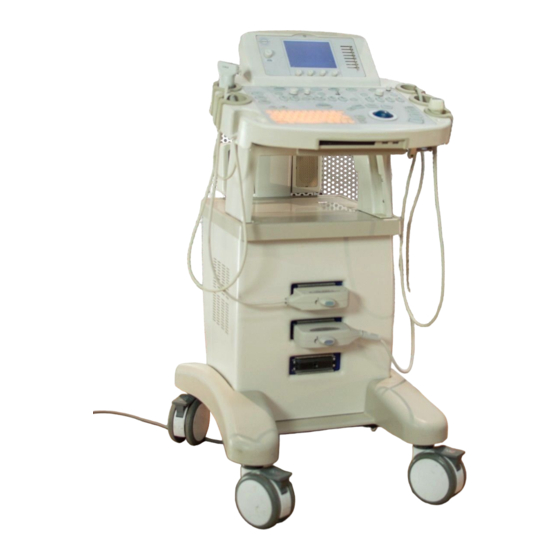
SYSTEM OVERVIEW The SONIX MDP Ultrasound System is a software driven, ergonomic, diagnostic medical device. It uses state of the art technologies to acquire, process and display ultrasound data (Figure 1-1). The system has several major field serviceable components including: LCD display with built-in speakers and a multi-position, articulated lift system, operator console, ultrasound modulo and transducers. -
Page 14: Physical Description
1.7.4 Transducers Ultrasonix offers a wide selection of high performance transducers for a variety of imaging applications. Incorporating the latest acoustic materials and technology, Ultrasonix’s lightweight transducers are ergonomic and durable for maximum clinical use. -
Page 15: Chapter 2: System Specifications
UI LANGUAGES (SELECTABLE) • English • Additional languages pending. ADDITIONAL SOFTWARE FEATURES • Pictograms • Preset and free-text annotations • Regional font and keyboard layout support (Mandarin, Arabic, etc.). SONIX MDP Service Manual 00.053.009, Revision A Chapter 2: System Specifications... -
Page 16: Electrical Ratings
Hungary ........220V Qatar..........220V Bahrain........220V Iceland ........220V Romania ........220V Bangladesh .......220V India .......... 220V Russian Federation....220V Barbados........110V Indonesia ......110/220V Saudi Arabia .......110/220V Belgium ......110V/220V Iran..........220V Senegal ........110V Chapter 2: System Specifications 00.053.009, Revision A SONIX MDP Service Manual... - Page 17 Vietnam ......110/220V Gambia ........220V Niger ..........220V Yemen ........220V Germany ........220V Nigeria ........220V Zaire ..........220V Ghana ........220V Norway ........220V Zambia ........220V Gibraltar ........220V Okinawa........110V Zimbabwe........220V SONIX MDP Service Manual 00.053.009, Revision A Chapter 2: System Specifications...
- Page 18 Chapter 2: System Specifications 00.053.009, Revision A SONIX MDP Service Manual...
-
Page 19: Chapter 3: System Installation
Warning: Operate in an indoor environment only, free from moisture, flammable liquids, gases, corrosive substances, strong electrical or magnetic fields and equipment that generates high frequency waves. Ultrasonix cannot guarantee the proper performance of the system if used in the above- listed conditions. Table 3-2: Barcode Reader Operating Temperature 32º... -
Page 20: Electrical Requirements
6 m long, CSA & UL approved 250Vac, 15A, 3 wire, 18 AWG, grounding type, 6-15P Hospital Grade plug 200-240V~, 47-63Hz cap, less than 6 m long, CSA & UL approved Chapter 3: System Installation 00.053.009, Revision A SONIX MDP Service Manual... -
Page 21: Electrostatic Discharge
Warning: The system should not be used adjacent to or stacked with other equipment. If adjacent or stacked use is necessary, the system should be observed in order to verify normal operation in the configuration in which it will be used. SONIX MDP Service Manual 00.053.009, Revision A Chapter 3: System Installation... -
Page 22: Wiring Requirements
CAT5 (Category 5, 10 Base-T, unshielded twisted pair). Caution: System networking options are intended for use inside your organization's firewall. Organizations that elect to configure/use the networking functionality provided by Ultrasonix are assuming all liabilities and risks associated with that decision. -
Page 23: Pre-Installation
"Tip and Tell" = Acceptable "Tip and Tell" = Unacceptable Report any damage to both the carrier and Ultrasonix. SONIX MDP Service Manual 00.053.009, Revision A Chapter 3: System Installation... -
Page 24: Installation
Cut and remove the four (4) ¼” nylon strap around the box. Caution: Stand out of the way when cutting these straps as they under tension and may snap back when severed. Lifting from the bottom, remove the cardboard cover. Chapter 3: System Installation 00.053.009, Revision A SONIX MDP Service Manual... - Page 25 Remove the plastic bag contain the two (2) Allen keys from the console packaging. Note: Keep the Allen keys handy as they will be required when mounting the arm for the LCD display (3.3.2). SONIX MDP Service Manual 00.053.009, Revision A Chapter 3: System Installation...
- Page 26 LCD display box (as in the above image) or on top of the transducers/peripherals. Chapter 3: System Installation 00.053.009, Revision A SONIX MDP Service Manual...
-
Page 27: Mounting The Lcd Display Arm
Remove the foam from around the LCD display arm base and lower arm. Note: The ends of the cable bundle are encased in bubble wrap. Lift the LCD display lower arm out of the foam packaging. SONIX MDP Service Manual 00.053.009, Revision A Chapter 3: System Installation... - Page 28 Note: Two (2) Allen keys are provided. They are enclosed in a small plastic bag and taped to the console packaging (3.3.1, step 5). Set the lower arm over the LCD display arm base. Chapter 3: System Installation 00.053.009, Revision A SONIX MDP Service Manual...
- Page 29 Using the 2.5mm Allen key, tighten the set screw at the base of the LCD display lower arm. Lift the LCD display upper arm (with tilt mechanism attached) out of the foam packaging. SONIX MDP Service Manual 00.053.009, Revision A Chapter 3: System Installation...
- Page 30 Using the 2.5mm Allen key, tighten the set screw at the base of the LCD display lower arm. Remove the bubble wrap from around the end of the cable bundle. Tuck the cable bundle into the clip under the upper arm. Chapter 3: System Installation 00.053.009, Revision A SONIX MDP Service Manual...
- Page 31 Remove the foam packaging that held the LCD display arm. Remove the LCD display box from the rear of the system and set it aside. SONIX MDP Service Manual 00.053.009, Revision A Chapter 3: System Installation...
-
Page 32: Uncrating Instructions
Remove any remaining foam packed around the system. Remove the lower front foam packaging and the bottom rear foam packaging. Retrieve the foam ramps previously removed (3.3.1) from the system packaging. Chapter 3: System Installation 00.053.009, Revision A SONIX MDP Service Manual... - Page 33 (both front and back) in order to roll it down the ramp. For safety reasons, Ultrasonix recommends backing the system off the palette from the rear. One person should grasp the rear handles while the second person should grab hold of the front of the Peripheral Shelf edge –...
- Page 34 The bottom portion shows one open depression (3) with a wedge in the middle (4) and the second depression (5) filled with the wedge provided in the base of the packaging. Back the system off the palette. Chapter 3: System Installation 00.053.009, Revision A SONIX MDP Service Manual...
-
Page 35: Mounting The Lcd Display
Note: Be sure to unpack the system (3.3.1), mount the LCD display arm (3.3.2) and uncrate the system (3.3.3) first. To Mount the LCD Display: Remove the LCD display box. Open the LCD display box and remove the thumbscrews and foam packing. SONIX MDP Service Manual 00.053.009, Revision A Chapter 3: System Installation... - Page 36 Note: The cable connectors must be carefully manipulated to fit through the available space. This step may take some time. Be sure to thread the speaker cable with the color-coded green tape towards the speaker connector labeled with the green dot. Chapter 3: System Installation 00.053.009, Revision A SONIX MDP Service Manual...
- Page 37 Make sure all the cables – especially the speaker cables – are securely tucked out of the way. Any cables that are pinched when the back cover of the LCD display is connected (in the next step) may cause a malfunction. SONIX MDP Service Manual 00.053.009, Revision A Chapter 3: System Installation...
- Page 38 Using the large, flat head screwdriver (or coin), close the four (4) locks on the LCD display cover by giving each a quarter turn to the right or left. Chapter 3: System Installation 00.053.009, Revision A SONIX MDP Service Manual...
-
Page 39: Barcode Reader
UNDER NO CIRCUMSTANCES should users or technicians attempt to open or service the laser scanner. Attempting to open the barcode reader may cause exposure to hazardous laser light. Should the barcode reader require maintenance or replacement, only qualified Ultrasonix Service Technicians may perform service as detailed in this Service Manual. -
Page 40: Ecg Cables
3.3.6 ECG Cables Refer Chapters 5 and 7 in the SONIX MDP User Manual for details on ECG imaging and ECG Measurements and Reports. Note: ECG functionality is a licensed option. To Inspect and Connect the ECG Cables: Unpack the ECG cables and inspect for damage. -
Page 41: Mechanical Inspection
Inform the facility's representative that the system is installed and ready for any safety testing they would normally conduct. Once it is running, the LCD display will show a black background image field with settings information or the patient ID menu. SONIX MDP Service Manual 00.053.009, Revision A Chapter 3: System Installation... -
Page 42: Peripherals
Caution: The power draw for peripherals connected via the System Case Connectivity Panel must NOT exceed 150W. Refer to the most recent Ultrasonix price list to determine the exact makes/models of Ultrasonix-approved devices. Chapter 3: System Installation 00.053.009, Revision A SONIX MDP Service Manual... -
Page 43: Voltage Configuration
3.3.12 Changing Fuses for details on how to remove the fuse box and replace the fuse(s). When changing the voltage settings, both the EMI filter and the voltage selector must be adjusted to the same setting. Figure 3-1: SONIX MDP EMI Filter and Voltage Selector EMI Filter Voltage Selector Figure 3-2: EMI Filter Location Caution: Always remove the rear shroud before attempting to access the EMI filter. - Page 44 Use the screwdriver to slide the voltage selector across to the correct position. Voltage Selector Caution: Be sure that the EMI filter and voltage selector readings are identical. Replace the rear shroud (7.1.11). Chapter 3: System Installation 00.053.009, Revision A SONIX MDP Service Manual...
-
Page 45: Changing Fuses
Note: It should not be necessary to use a screwdriver to remove the fuses. Reinsert the fuse box. Caution: Ensure the correct voltage setting is visible. Close the fuse box lid. Replace the rear shroud (7.1.11). SONIX MDP Service Manual 00.053.009, Revision A Chapter 3: System Installation... -
Page 46: System Case Connectivity Panel
"Not in use" and therefore will no affect on MDP functionality. Figure 3-3: System Case Connectivity Panel (SXMDP 1.0–1.1) Figure 3-4: System Case Connectivity Panel (SXMDP 1.2) Chapter 3: System Installation 00.053.009, Revision A SONIX MDP Service Manual... - Page 47 Two (2) additional USB ports. These ports may be used to USB ports (2) connect printers and other Ultrasonix-approved USB peripherals. Use to connect the barcode reader. Line-in (blue): may be used to connect an Ultrasonix-approved audio input device. Sound connections System Speaker connection (green).
- Page 48 17 Console power connector Used by the operator console. May be used to trigger a freeze or print function by connecting directly to an Ultrasonix-approved switching device, such as a Footswitch. Freeze (2) Bayonet Neill Concelman (BNC) Note: During configuration, enable Footswitch 2 for this connector.
-
Page 49: Back Connectivity Panel
The SONIX system provides two (2) USB ports and a CD/DVD writer at the front of the operator console. These USB Ports can be used to connect Ultrasonix-approved USB devices (such as a USB thumb drive) for image file transfer. - Page 50 Chapter 3: System Installation 00.053.009, Revision A SONIX MDP Service Manual...
-
Page 51: Chapter 4: Performance Testing
If found, test with the other transducers to verify the non-visible element(s) is in the same location. Try different transducer connectors to eliminate the possibility of a malfunctioning transducer. SONIX MDP Service Manual 00.053.009, Revision A Chapter 4: Performance Testing... -
Page 52: Removable Hardware Test
Note: There is a level indicator on the LCD display. The sound of static should be audible. Note: If static is not audible, use the trackball to move the gate away from the top of the LCD display. Chapter 4: Performance Testing 00.053.009, Revision A SONIX MDP Service Manual... -
Page 53: Licenses
Press the console MENU button. Select Administrator > Licensing. If none of the licenses are Active, reload license.key following the instructions in section 10.2 Re-Import License.Key from a Local Drive. SONIX MDP Service Manual 00.053.009, Revision A Chapter 4: Performance Testing... - Page 54 Chapter 4: Performance Testing 00.053.009, Revision A SONIX MDP Service Manual...
-
Page 55: Chapter 5: Software
CHAPTER 5: SOFTWARE SOFTWARE MODES The system comes equipped with many modes of operations. Refer to the SONIX MDP User Manual for complete details. SOFTWARE UPDATE VIA THE INTERNET To Update via the Internet: Press the console MENU button. Click on Administrator > Software Updates. -
Page 56: System Recovery
Representative for further instructions. SYSTEM RECOVERY Before performing a system recovery on the system, consult an Ultrasonix Technical Support Representative as this should only be done as a last resort. Technical Support will provide you with the appropriate documentation to carry out a system recovery. -
Page 57: Chapter 6: Connect Peripherals
Connect the other end of the USB printer cable to the rear of the printer. Connect the power pack to the rear of the printer, then plug it into a power outlet. SONIX MDP Service Manual 00.053.009, Revision A Chapter 6: Connect Peripherals... - Page 58 Press the power button to turn on the printer (left front side). Press the console MENU button. Click on Administrator > Peripherals. In the Paper Printer dialog, double click on Add Printer. Chapter 6: Connect Peripherals 00.053.009, Revision A SONIX MDP Service Manual...
- Page 59 Click on Next. De-select Automatically detect and install my Plug and Play printer, then click Next. SONIX MDP Service Manual 00.053.009, Revision A Chapter 6: Connect Peripherals...
- Page 60 USB) from the drop down menu. Click Next. Find the HP Deskjet 5400 series CD-ROM that came with the printer and put it in the console CD-ROM drive. Select Have Disk. Chapter 6: Connect Peripherals 00.053.009, Revision A SONIX MDP Service Manual...
- Page 61 Note: A message may pop-up asking if you want to set this printer up as the default printer. If this is the default printer, click Yes. Click OK. Select HP Deskjet 5400 Series from the list of available Printers and click on Next. SONIX MDP Service Manual 00.053.009, Revision A Chapter 6: Connect Peripherals...
- Page 62 Select Do not share this printer, then click on Next. To print a test page select Yes and click on Next. Chapter 6: Connect Peripherals 00.053.009, Revision A SONIX MDP Service Manual...
- Page 63 If the test page printed properly, click OK. Note: Reboot the system if the printer does not show up under MENU > Administrator > Peripherals. Installation of the Local Printer is complete. SONIX MDP Service Manual 00.053.009, Revision A Chapter 6: Connect Peripherals...
- Page 64 Select the desired Print Key tab: Print 1, Print 2 or Print 3. Note: Each of the three (3) tabs corresponds to one of three (3) PRINT buttons on the console. Select the Printer checkbox. Click OK. Chapter 6: Connect Peripherals 00.053.009, Revision A SONIX MDP Service Manual...
-
Page 65: Network Printer Setup: Hp Deskjet 5440
Note: Before proceeding, ensure that the network has a shared printer. Contact your System Administrator if you are not sure. Press the console MENU button. Click on Administrator > Peripherals. In the Paper Printer dialog, double click on Add Printer. SONIX MDP Service Manual 00.053.009, Revision A Chapter 6: Connect Peripherals... - Page 66 Click on Next. Select Browse for a printer. Click Next. Chapter 6: Connect Peripherals 00.053.009, Revision A SONIX MDP Service Manual...
- Page 67 Select the appropriate shared (network) printer and click Next. Click Yes to continue. Select Yes. Click Next to print a test page. SONIX MDP Service Manual 00.053.009, Revision A Chapter 6: Connect Peripherals...
- Page 68 Select the desired Print Key tab: Print 1, Print 2 or Print 3. Note: Each of the three (3) tabs corresponds to one of three (3) buttons on the PRINT console. Select the Printer checkbox. Click OK. Chapter 6: Connect Peripherals 00.053.009, Revision A SONIX MDP Service Manual...
-
Page 69: Video Graphic Printer (Local, Thermal Transfer Printer)
Note: If your printer requires a different plug, you may need to plug into an external power outlet. Press the power button on the video graphic printer. Press the console MENU button. Click Administrator > Peripherals. SONIX MDP Service Manual 00.053.009, Revision A Chapter 6: Connect Peripherals... - Page 70 Note: Customers may elect to use a different PRINT key to perform this function. Select the Print 1, 2 or 3 tab as per the customer's preference. Click OK. Click Close. Click Close. Chapter 6: Connect Peripherals 00.053.009, Revision A SONIX MDP Service Manual...
- Page 71 If the image is not printed or a beep is heard, double-check all the connections. Neatly tuck in the cables (as shown below). Video graphic printer installation is now complete. SONIX MDP Service Manual 00.053.009, Revision A Chapter 6: Connect Peripherals...
- Page 72 PRINT 1, PRINT 2 and PRINT 3/ARCHIVE. Select the Trigger option then press OK. To print a test image on the thermal printer, hit the corresponding console PRINT button. Chapter 6: Connect Peripherals 00.053.009, Revision A SONIX MDP Service Manual...
-
Page 73: Image Sheet Printing
To print one image per sheet, set Columns to 1 and Rows to 1. This will result in a single, large image. Make certain the Enable box is checked. Click OK. SONIX MDP Service Manual 00.053.009, Revision A Chapter 6: Connect Peripherals... - Page 74 Chapter 6: Connect Peripherals 00.053.009, Revision A SONIX MDP Service Manual...
-
Page 75: Chapter 7: Field Service Components
CD, DVD, etc). This will ensure access to this data if either the modulo or hard drive needs replaced during servicing. The following options are available for export: Note: When creating a backup prior to servicing or replacing the modulo, Ultrasonix recommends selecting all options for Export. •... - Page 76 Select Administrator > System > Export…. Check the items to be exported. Note: When creating a backup prior to servicing or replacing the modulo, Ultrasonix recommends selecting all options for Export. Use Select All to check all items at one time and Clear All to clear all checkboxes.
-
Page 77: Exporting Patient/Exam Data (As Required)
Equipment/Tools Required: • USB memory stick or removable disk (CD, DVD, etc). To Export all Patient/Exam Data Using SONIX MDP Software: Press the console ID button. Click the Import/Export button. Select all Patients/Exams. From the Source drop-down menu, select Local Patient Data. - Page 78 When the Export is complete, the following message will be presented. Note: If Delete On Export Options were selected, the data will be deleted before the Export process is complete message is presented. Chapter 7: Field Service Components 00.053.009, Revision A SONIX MDP Service Manual...
-
Page 79: Backup Patient Data Via The Service Mode Option
Connect the USB storage device to the Front Console. Press the console MENU button. Select Administrator > Service… and type in the Service Mode Password using the console keyboard. Select OK. SONIX MDP Service Manual 00.053.009, Revision A Chapter 7: Field Service Components... - Page 80 Select OK to continue or Cancel to exit without creating a backup. Once the Backup procedure is complete, the following message will be presented. Click OK to continue. Chapter 7: Field Service Components 00.053.009, Revision A SONIX MDP Service Manual...
-
Page 81: Backing-Up License.key And Dongle.txt (As Required)
Using the trackball and console UPDATE button, click on license.key in the Name list on the right. Using the trackball and console SELECT button click on Send To > Removable Disk (F:). SONIX MDP Service Manual 00.053.009, Revision A Chapter 7: Field Service Components... - Page 82 Press the Windows START key on the USB or PS2 keyboard and select Run. Note: Leave Windows Explorer running. Type cmd and press ENTER. At the command prompt, type cd \program files\ultrasonix\exam and press ENTER. Note: Be sure to include the space between "cd" and "\" and between the words "program"...
- Page 83 Close the Notepad window by clicking on the "X" in the top right corner. Close Windows Explorer by clicking on the "X" in the top right corner. Press the console power button once to shut down the system. SONIX MDP Service Manual 00.053.009, Revision A Chapter 7: Field Service Components...
-
Page 84: Removing The Front Shrouds
Unfasten the two (2) thumbscrews under the front wheelbase shroud. Remove the front wheelbase shroud. Grasp the front shroud by the sides and tip the bottom outwards. Once it clears the wheelbase frame it can be removed. Chapter 7: Field Service Components 00.053.009, Revision A SONIX MDP Service Manual... -
Page 85: Accessing The Ultrasound Modulo
Using the 7mm socket wrench, remove the four (4) bolts/washers securing the stiffener frame to the system frame. Front edge of the wheelbase frame. Remove the stiffener frame. SONIX MDP Service Manual 00.053.009, Revision A Chapter 7: Field Service Components... -
Page 86: Removing The Rear Shroud
Using the 4mm Allen Key, unfasten the four (4) screws and fender washers. Tip the top of the shroud backwards until it clears the peripherals shelf, then remove it. Chapter 7: Field Service Components 00.053.009, Revision A SONIX MDP Service Manual... -
Page 87: Removing The Ultrasound Modulo
Open the System Case Connectivity Panel cover and undo all modulo cables/connections, cutting any cable ties as needed. Note: Due to the number of connections involved in this and the next few steps, Ultrasonix recommends marking the location of all unlabeled wires/cables by labeling them with masking tape. - Page 88 Check the rear of the modulo and disconnect any remaining cables running from the modulo to the system. Using the 10mm wrench, undo the grounding strap connection. Pull the modulo forward until it can be lifted from the system frame. Chapter 7: Field Service Components 00.053.009, Revision A SONIX MDP Service Manual...
-
Page 89: Installing The Ultrasound Modulo
Push the modulo back and position the stiffener frame so that the four (4) bolt holes line up. Using the 7mm socket wrench, fasten the four (4) bolts/washers securing the stiffener frame to the system frame. Reconnect the grounding strap connection. SONIX MDP Service Manual 00.053.009, Revision A Chapter 7: Field Service Components... - Page 90 Use as many cable ties as necessary to keep all cables neat and tucked out of the way. Reinstall the rear shroud (7.1.11). Reinstall the front shrouds (7.1.10). Chapter 7: Field Service Components 00.053.009, Revision A SONIX MDP Service Manual...
-
Page 91: Reinstalling The Front Shrouds
Slip the front wheelbase shroud over the rails on the wheelbase and press back into place. Wheelbase rail Wheelbase rail Fasten the two (2) thumbscrews under the front wheelbase shroud. SONIX MDP Service Manual 00.053.009, Revision A Chapter 7: Field Service Components... -
Page 92: Reinstalling The Rear Shroud
Power off, unplug the system and remove the power cord. Using the 4mm Allen Key, unfasten the four (4) screws and fender washers. Chapter 7: Field Service Components 00.053.009, Revision A SONIX MDP Service Manual... -
Page 93: Importing User Data (As Required)
Plug the previously-created removable disk (USB key, CD, DVD, etc) into one of the USB ports at the front of the console. Press the console MENU button. Click on Administrator > System > Import…. Select the items to be imported. SONIX MDP Service Manual 00.053.009, Revision A Chapter 7: Field Service Components... - Page 94 A completion dialog will be presented when the export process has finished (this will take approximately 15-45 seconds). Caution: Ultrasonix does not recommend importing user-defined Imaging Presets created with a previous software version as they may not be compatible for use with a more recent software update.
-
Page 95: Importing Patient/Exam Data (As Required)
When the Import is complete, the following message will be presented. Note: If the data selected for Import is already available on the system, it will not be imported, i.e., it will not overwrite the existing data. SONIX MDP Service Manual 00.053.009, Revision A Chapter 7: Field Service Components... -
Page 96: Restore Patient Data Via The Service Mode Option
Connect the USB storage device to the Front Console. Press the console MENU button. Select Administrator > Service…. Type in the Service Mode Password using the console keyboard. Click OK. Chapter 7: Field Service Components 00.053.009, Revision A SONIX MDP Service Manual... - Page 97 When patient data already exists on the system, a final warning will be presented. Click Yes to continue or No exit with restoring patient data. Once the Restore procedure is complete, the following message will be presented. Click OK to continue. SONIX MDP Service Manual 00.053.009, Revision A Chapter 7: Field Service Components...
-
Page 98: Re-Import License.key (If Required)
However, if the customer purchased optional license keys, re- issuing the additional licenses may be required. Refer to Chapter 10: License.key Importation for details on re-importing license.key. Chapter 7: Field Service Components 00.053.009, Revision A SONIX MDP Service Manual... -
Page 99: Ultrasound Modulo Servicing - Internal Components
Ensure that excessive stress is not being placed on the cables in the System Case Connectivity Panel. If this occurs, the cables will have to disconnected before continuing. SONIX MDP Service Manual 00.053.009, Revision A Chapter 7: Field Service Components... -
Page 100: Opening The Front Block (With Or Without Removing The Modulo)
Using the #2 Phillips screwdriver, unfasten the two (2) screws securing the Front Block. Note: The screws will be labeled with a service access sticker. Swing open the Front Block door to expose the interior. Chapter 7: Field Service Components 00.053.009, Revision A SONIX MDP Service Manual... -
Page 101: Removing The Front Block
To remove the door, undo the two (2) hinges (two (2) screws per hinge. Note: The arrows (above) mark the two (2) screws on the top hinge. The Front Block can now be removed. SONIX MDP Service Manual 00.053.009, Revision A Chapter 7: Field Service Components... -
Page 102: Reinstalling The Front Block
PCI card (1) is connected to the bottom plug on the ultrasound modulo (2). Consequently, the bottom of the PCI card is connected to the top plug on the ultrasound modulo. Chapter 7: Field Service Components 00.053.009, Revision A SONIX MDP Service Manual... - Page 103 This will also ensure that no undue stress is placed upon the cables the next time the Front Block is opened. Secure the door with the two (2) service access screws. Reinstall the modulo (7.1.9) and the front shrouds (7.1.10). SONIX MDP Service Manual 00.053.009, Revision A Chapter 7: Field Service Components...
-
Page 104: Closing The Front Block (With Or Without Removing The Modulo)
This will also ensure that no undue stress is placed upon the cables the next time the Front Block is opened. Secure the door with the two (2) service access screws. If required, reinstall the modulo (7.1.9) Reinstall the front shrouds (7.1.10). Chapter 7: Field Service Components 00.053.009, Revision A SONIX MDP Service Manual... -
Page 105: Replacing The Ecg Module
To Replace the ECG Module: Using the #2 Phillips screwdriver, fasten the two (2) sets of screws and washers. Connect the ECG cable to the ECG module. Reinstall the modulo (7.1.9). SONIX MDP Service Manual 00.053.009, Revision A Chapter 7: Field Service Components... -
Page 106: Lcd Display Servicing
Using the large, flat head screwdriver, open the four (4) locks on the LCD display cover by giving each a quarter turn to the right or left. "Closed" position Chapter 7: Field Service Components 00.053.009, Revision A SONIX MDP Service Manual... - Page 107 Feed the disconnected cables through the cableway at the bottom of the LCD display. Cableway Note: The cable connectors must be carefully manipulated to fit through the available space. This step may take some time. Remove the LCD display. SONIX MDP Service Manual 00.053.009, Revision A Chapter 7: Field Service Components...
-
Page 108: Installing The Lcd Display (With Integrated Speakers)
Be sure to thread the speaker cable with the color-coded green tape towards the speaker connector labeled with the green dot. Place the LCD display in position and hold securely with one hand. Chapter 7: Field Service Components 00.053.009, Revision A SONIX MDP Service Manual... - Page 109 Make sure all the cables – especially the speaker cables – are securely tucked out of the way. Any cables that are pinched when the back cover of the LCD display is connected (in the next step) may cause a malfunction. SONIX MDP Service Manual 00.053.009, Revision A Chapter 7: Field Service Components...
- Page 110 Using the large, flat head screwdriver, close the four (4) locks on the LCD display cover by giving each a quarter turn to the right or left. Perform a reset on the LCD display following the instructions listed immediately below. Chapter 7: Field Service Components 00.053.009, Revision A SONIX MDP Service Manual...
- Page 111 To Reset the LCD Display: Press the console MENU button. Select Administrator > Peripherals> LCD Display Click on the Restore Factory button. SONIX MDP Service Manual 00.053.009, Revision A Chapter 7: Field Service Components...
-
Page 112: Replacing The Lcd Display
Push gently on the bottom of the frame to move it up past the top of the LCD display. This will unhook the top of the frame from the LCD display and allow it to be removed. Chapter 7: Field Service Components 00.053.009, Revision A SONIX MDP Service Manual... - Page 113 Use a #2 Phillips screwdriver to re-fasten the four (4) central screws holding the LCD display to metal frame, using the screws removed in step 4. Reinstall the LCD display (7.3.2). SONIX MDP Service Manual 00.053.009, Revision A Chapter 7: Field Service Components...
-
Page 114: Replacing Lcd Display Arm Components
Caution: Take care to hold the tilt plate mechanism firmly otherwise it, the fastener and washers will drop to the floor once the bolt has been completely loosened. Chapter 7: Field Service Components 00.053.009, Revision A SONIX MDP Service Manual... - Page 115 Release the cable bundle from the clip under the upper arm. Using the 2.5mm Allen key, loosen the set screw just enough to remove the upper arm. Once the arm has been removed, retighten the set screw. SONIX MDP Service Manual 00.053.009, Revision A Chapter 7: Field Service Components...
- Page 116 Clip the cable ties attaching the cable bundle to the lower arm. Using the 2.5mm Allen key, loosen the set screw just enough to remove the lower arm. Once the arm has been removed, retighten the set screw. Chapter 7: Field Service Components 00.053.009, Revision A SONIX MDP Service Manual...
-
Page 117: Reinstalling Lcd Display Arm Components
Connect the cable bundle to the lower arm with two (2) cable ties. Reinstall the LCD display upper arm and tilt plate mechanism (below). Reinstall the LCD display (7.3.2). SONIX MDP Service Manual 00.053.009, Revision A Chapter 7: Field Service Components... - Page 118 Using the 2.5mm Allen key, tighten the set screw. Insert the cable bundle in clip under the upper arm. If required, reinstall the LCD display arm tilt plate mechanism (below). Reinstall the LCD display (7.3.2). Chapter 7: Field Service Components 00.053.009, Revision A SONIX MDP Service Manual...
- Page 119 Carefully ensure that all washers are in the correct order. Using the 4mm Allen key, fasten the tilt plate mechanism to the upper arm Reinstall the LCD display (7.3.2). SONIX MDP Service Manual 00.053.009, Revision A Chapter 7: Field Service Components...
-
Page 120: Speaker Servicing
This lock is in the "Closed" position. Once the locks have been disengaged, remove the back cover. Disconnect both speaker cables. Right speaker cable Chapter 7: Field Service Components 00.053.009, Revision A SONIX MDP Service Manual... - Page 121 Caution: Be sure to hold on to the speaker cover during this step, otherwise it will drop to the floor when the second screw is undone. Repeat step 5 on the other side of the LCD display. Replace the covers by reversing the above steps. SONIX MDP Service Manual 00.053.009, Revision A Chapter 7: Field Service Components...
-
Page 122: Removing/Replacing The Speakers
Replace both vibration dampers then refasten the two (2) screws with the #1 Phillips screwdriver. Draw the wiring down towards the bottom and, using your fingers, reconnect the speaker socket. Reverse the steps in 7.5.1 to replace the speaker covers. Chapter 7: Field Service Components 00.053.009, Revision A SONIX MDP Service Manual... -
Page 123: Transducer Testing
Note: Refer to Figure 7-2 for an example of an acceptable transducer image. If there is any doubt about the image, contact Ultrasonix Technical Support and forward them a digital copy of the image in question for verification of the diagnosis. -
Page 124: Testing The Transducer Board
Note: Refer to Figure 7-2 for an example of an acceptable transducer image. If there is any doubt about the image, contact Ultrasonix Technical Support and forward them a digital copy of the image in question for verification of the diagnosis. -
Page 125: Returning Parts For Service/Repair/Replacement
7.6.1 Transducers When shipping transducers for service/repair/replacement, it is the customer's responsibility to ensure that each transducer meets the requirements laid out in 12.5 Shipping Transducers for Service. SONIX MDP Service Manual 00.053.009, Revision A Chapter 7: Field Service Components... - Page 126 Chapter 7: Field Service Components 00.053.009, Revision A SONIX MDP Service Manual...
-
Page 127: Chapter 8: Dicom Configuration
Press the console MENU button. Select Administrator > DICOM. Select/deselect the appropriate Turn on… checkbox beside the desired feature (Storage, Print or Worklist) in order to activate/deactivate access to a DICOM feature. SONIX MDP Service Manual 00.053.009, Revision A Chapter 8: DICOM Configuration... -
Page 128: Dicom Storage Configuration
Click the associated Settings button. An onscreen dialog with four (4) tabs will be presented: AE (Application Entity) Configuration, Storage Settings, Brightness/Contrast and Storage Commitment. Configure the four (4) dialogs as required. Chapter 8: DICOM Configuration 00.053.009, Revision A SONIX MDP Service Manual... - Page 129 Select to send verification request to DICOM Storage device (ping to verify Connection Test connection). Insert (Symbol) Use to insert text symbol(s) not available on the console keyboard (e.g., apostrophe). SONIX MDP Service Manual 00.053.009, Revision A Chapter 8: DICOM Configuration...
- Page 130 Select to enable the display of DICOM Storage error messages (e.g., Failed Show Error Balloons to connect to DICOM). Use to insert text symbol(s) not available on the console keyboard (e.g., Insert (Symbol) apostrophe). Chapter 8: DICOM Configuration 00.053.009, Revision A SONIX MDP Service Manual...
- Page 131 Note: To adjust the Brightness/Contrast settings, position the trackball arrow over the Reset Brightness or Contrast slider. Press and hold the SELECT button while moving the trackball left or right to the desired position. SONIX MDP Service Manual 00.053.009, Revision A Chapter 8: DICOM Configuration...
- Page 132 AE Title of the Storage Commitment Listener SCU. Port Listening Port. Packet Data Unit (PDU) Size PDU size in bytes. Use to insert text symbol(s) not available on the console keyboard (e.g., Insert (Symbol) apostrophe). Chapter 8: DICOM Configuration 00.053.009, Revision A SONIX MDP Service Manual...
-
Page 133: Dicom Print Configuration
Click the associated Settings button. An onscreen dialog with four (4) tabs will be presented: AE Configuration, Print Settings, Advanced Print Settings and Brightness/Contrast. Configure the four (4) dialogs as required. SONIX MDP Service Manual 00.053.009, Revision A Chapter 8: DICOM Configuration... - Page 134 Connection Test Select to send verification request to DICOM Print device (ping to verify connection). Insert (Symbol) Use to insert text symbol(s) not available on the console keyboard (e.g., apostrophe). Chapter 8: DICOM Configuration 00.053.009, Revision A SONIX MDP Service Manual...
- Page 135 Select the location to which the print job will be sent: Processor or Magazine. Use to insert text symbol(s) not available on the console keyboard (e.g., Insert (Symbol) apostrophe). SONIX MDP Service Manual 00.053.009, Revision A Chapter 8: DICOM Configuration...
- Page 136 Enter the type of Polarity to be used. Image Size Enter the printer-specific Image Size in mm. Use to insert text symbol(s) not available on the console keyboard (e.g., Insert (Symbol) apostrophe). Chapter 8: DICOM Configuration 00.053.009, Revision A SONIX MDP Service Manual...
- Page 137 Note: To adjust the Brightness/Contrast settings, position the trackball arrow over the Reset Brightness or Contrast slider. Press and hold the SELECT button while moving the trackball left or right to the desired position. SONIX MDP Service Manual 00.053.009, Revision A Chapter 8: DICOM Configuration...
-
Page 138: Dicom Worklist Configuration
Select Administrator > DICOM. Check Turn on DICOM Print. Click the associated Settings button. An onscreen dialog with one (1) tab will be presented: AE Configuration. Configure the dialog as required. Chapter 8: DICOM Configuration 00.053.009, Revision A SONIX MDP Service Manual... - Page 139 Select to send verification request to DICOM Worklist device (ping to verify Connection Test connection). Insert (Symbol) Use to insert text symbol(s) not available on the console keyboard (e.g., apostrophe). SONIX MDP Service Manual 00.053.009, Revision A Chapter 8: DICOM Configuration...
- Page 140 Chapter 8: DICOM Configuration 00.053.009, Revision A SONIX MDP Service Manual...
-
Page 141: Chapter 9: Network Connection
The system can be configured to connect to the local network. The network connection can be made either through a hard-wired LAN or Dialup connection. Note: A dialup connection requires a third party, USB modem. Contact your dealer or Ultrasonix Technical Support to learn more about this option. -
Page 142: Ethernet (Lan) Network Configuration
IP address, Subnet mask, and Default gateway. Select OK and press the console MENU button to exit the menu system. Note: It may be necessary to restart in order for the changes to take affect. Chapter 9: Network Connection 00.053.009, Revision A SONIX MDP Service Manual... -
Page 143: Ethernet (Lan) Communication Test
To Perform an Ethernet (LAN) Communication Test: Press the console QSONIX button. Select Online Support. This should connect the system to an Ultrasonix Technical Support Representative. Note: It may be necessary to restart in order for these changes to take affect. -
Page 144: Dialup Network Configuration (If Available)
Dialup Network Configuration (If Available) Note: A dialup connection requires a third party, USB modem. Contact your dealer or Ultrasonix Technical Support to learn more about this option. Figure 9-3: Network Configuration Page (Dialup) To Configure a Dial-up Connection (If Available): Connect the modem's USB connector to connection point 7. -
Page 145: Dialup Communication Test
To Perform a Dialup Communication Test: Press the console QSONIX button. Select Online Support. This should connect the system to an Ultrasonix Technical Support Representative. Note: While the system is dialing out, the current dialing status to your ISP will be displayed. -
Page 146: Remote Support
REMOTE SUPPORT Remote support allows Ultrasonix Technical Support to view and control the SONIX for diagnostic purposes. In order to use Remote Support, a PIN (Personal Identification Number) must be obtained from Ultrasonix Technical Support. Note: The PIN is valid for 20 minutes only, so be sure to use it right away. -
Page 147: Chapter 10: License.key Importation
Click on Administrator > Licensing. Make note of the System Identification Number shown in the Licensing window and forward it to Ultrasonix Technical Support to obtain a license.key file. When the license.key file arrives, copy it to a USB Memory stick. -
Page 148: Re-Import License.key From A Local Drive
Under the Look in drop-down menu, select Local Disk (D:) and locate license.key. Click Open to re-import license.key. Note: If there are any problems, contact Ultrasonix Technical Support for assistance. Error! Reference source not found. 00.053.009, Revision A SONIX MDP Service Manual... -
Page 149: Chapter 11: Maintenance
Check for good air flow without excessive noise. The wheels have sealed bearings therefore no lubrication is Cart Clean as necessary necessary. Electronics Six (6) months To be performed only by qualified service personnel. SONIX MDP Service Manual 00.053.009, Revision A Chapter 11: Maintenance... -
Page 150: System Cleaning
11.2 SYSTEM CLEANING Ultrasonix recommends the following cleaning instructions for all external surfaces, including the cart, cables and connectors. Cautions: Power off and unplug the system before cleaning. Do not spill or spray water on the controls, transducer connection receptacle, or transducer ports. -
Page 151: Touch Screen
Apply a small amount of one of the following recommended cleaning solutions to a soft, non- abrasive cloth and wipe down the console: • Water • Mild detergent (PH level at or near 7) and water solution. SONIX MDP Service Manual 00.053.009, Revision A Chapter 11: Maintenance... -
Page 152: Filter Cleaning
Caution: Power off and unplug the system prior to cleaning fan filters. The SONIX MDP comes equipped with a double layer filtering system. The first layer, or system filter, is accessible simply by removing the front wheelbase shroud and front shroud. The second layer (fan filters) is attached to the modulo and necessitates modulo removal. -
Page 153: Cleaning And Reinstalling The System Filter
Reinsert the filter in the same place between the modulo and exterior side shroud, pushing it back far enough to clear the bolts that attach the front stiffener to the system frame. Replace the front shrouds (7.1.8). SONIX MDP Service Manual 00.053.009, Revision A Chapter 11: Maintenance... -
Page 154: Modulo Fan And Exhaust Filter Cleaning
Modulo Fan Filters Vacuum both sides of the filter. Note: The filter itself is loose within it's frame, so take care when vacuuming. Reinstall the six (6) fan filters. Chapter 11: Maintenance 00.053.009, Revision A SONIX MDP Service Manual... - Page 155 Modulo Exhaust Filters If necessary, use a #2 Phillips screwdriver to remove them, then vacuum both sides. Reinstall the exhaust fan covers. Reinstall the modulo (7.1.9). Reinstall the front shrouds (7.1.10). SONIX MDP Service Manual 00.053.009, Revision A Chapter 11: Maintenance...
-
Page 156: Fan Cleaning
CPU (Central Processing Unit) Fan • Side Fans on Chassis • Cooling fans on Front Block. Use a vacuum cleaner to remove the dust from the external side vents of the system. Chapter 11: Maintenance 00.053.009, Revision A SONIX MDP Service Manual... -
Page 157: Transducer Maintenance
Immersing it beyond the first seam can destroy its electrical safety features. 11.3.1 Usage Guidelines Ultrasonix recommends inspecting the transducers prior to each use. • Ensure the transducers are always clean before they are used. There must be no ultrasound gel (from previous imaging), any debris, films or unusual odors present. -
Page 158: Ultrasound Coupling Gels
• Acetone • Methanol • Denatured ethyl alcohol • Mineral oil • Iodine • Any lotions or gels that contain perfume. If there are any questions, contact Ultrasonix Medical Corporation. Chapter 11: Maintenance 00.053.009, Revision A SONIX MDP Service Manual... -
Page 159: Cleaning/Disinfecting Recommendations And Warnings For All Non-Invasive Transducers
DO NOT use sterilization or disinfection methods that have not been recommended by Ultrasonix. Severe damage will result. Contact Ultrasonix if you have any doubt about sterilization or disinfection methods. Warning: Any transducer suspected of being contaminated with Creutzfeld Jacob disease material cannot be cleaned or sterilized. -
Page 160: Cleaning (Non-Invasive Transducers)
Low level disinfectants • Cidex plus • Sani-Cloth • Wavicide ® • T-spray • Omnicide 11.3.3.3 Sterilization (Non-Invasive Transducers) Sterilization of transducers is not possible. Follow the instructions for disinfection (above) instead. Chapter 11: Maintenance 00.053.009, Revision A SONIX MDP Service Manual... -
Page 161: Maintenance (Non-Invasive Transducers)
Ultrasonix. DO NOT use sterilization or disinfection methods that have not been recommended by Ultrasonix. Severe damage will result. Contact Ultrasonix if you have any doubt about sterilization or disinfection methods. Use of non-recommended cleaning agents may cause damage to the housing and will void transducer warranties. -
Page 162: Storing And Packaging (Non-Invasive Transducers)
DO NOT use sterilization or disinfections methods that have not been recommended by Ultrasonix. Severe damage will result. Contact Ultrasonix if you have any doubt about sterilization or disinfection methods. Warning: Any transducer suspected of being contaminated with Creutzfeld Jacob disease material cannot be cleaned or sterilized. -
Page 163: Cleaning (Invasive Transducers)
Table A-1: Recommended Disinfectants for Disinfecting Invasive Transducers High level disinfectants • Cidex plus • Wavicide ® • Omnicide 11.3.4.3 Sterilization (Invasive Transducers) Sterilization of transducers is not possible. Follow the instructions for disinfection (above) instead. SONIX MDP Service Manual 00.053.009, Revision A Chapter 11: Maintenance... -
Page 164: Maintenance (Invasive Transducers)
Ultrasonix. DO NOT use sterilization or disinfection methods that have not been recommended by Ultrasonix. Severe damage will result. Contact Ultrasonix if you have any doubt about sterilization or disinfection methods. Use of non-recommended cleaning agents may cause damage to the housing and will void transducer warranties. -
Page 165: Storing And Packaging (Invasive Transducers)
(11.3.3.6 and 11.3.3.6) • all shipping waybills/paperwork is completed as per the relevant regulations and laws. Refer to 7.8 Returning Parts for Service/Repair/Replacement for more details on transducer return or replacement. SONIX MDP Service Manual 00.053.009, Revision A Chapter 11: Maintenance... - Page 166 Chapter 11: Maintenance 00.053.009, Revision A SONIX MDP Service Manual...
-
Page 167: Chapter 12: Troubleshooting
12.4 CD/DVD DRIVE NOT RECOGNIZED The system's CD/DVD drive is a Panasonic UJ-845-B. It can accept CD-R, CD-RW, DVD+R, DVD-R and DVD±RW. • A.3 Ensure the CD/DVD Drive is Recognized. SONIX MDP Service Manual 00.053.009, Revision A Chapter 12: Troubleshooting... -
Page 168: Cd/Dvd Backups Failing
12.5 CD/DVD BACKUPS FAILING Ultrasonix recommends using HP brand of CDs and DVDs when creating discs. If you experience any failures when attempting to create a CD or DVD backup disc, contact Technical Support. 12.6 REGEDIT Some settings in the registry may need to be edited. -
Page 169: Sonix Does Not Boot, Error Is Displayed On The Lcd Display
System Recovery will need to be performed. Locate the System Recovery CD which came with the system and contact Ultrasonix Technical Support for further instructions. Caution: Do not attempt a System Recovery without first consulting an Ultrasonix Technical Support Representative. -
Page 170: Initialization Failures
If the initialization process fails at some point, refer to sections 12.12.1 to 12.12.4 in order to troubleshoot the problem. Figure 12-1: LCD Display - Successful Initialization Image Figure 12-2: Touch Screen - Successful Initialization Image Chapter 12: Troubleshooting 00.053.009, Revision A SONIX MDP Service Manual... -
Page 171: Electronics Initialization Failure
12.12.1 Electronics Initialization Failure The Ultrasonix PCI card is loose or not connected. Check the relevant cable connections using the following directions: • 7.1.4 Removing the Front Shroud • 7.1.5 Accessing the Ultrasound Modulo • 7.2.2 Opening the Front Block (It will only be necessary to open the Front Block door in order to access the PCI card cables) •... -
Page 172: Clarity Dongle Or Key Not Found
12.13 CLARITY DONGLE OR KEY NOT FOUND This data is presented if the Clarity license provided by the Clarity key or dongle isn’t found. • A.11 Clarity Dongle or Key Not Found. Chapter 12: Troubleshooting 00.053.009, Revision A SONIX MDP Service Manual... -
Page 173: Appendix A: Troubleshooting Solutions
Test System Power Up To Test System Power Up: Ensure the system is plugged in and powered on. If the system still does not power up, contact Ultrasonix for further instructions. A.1.2 Check Fuses/Voltage Selector To Check the Fuses/Voltage Selector: Power off and unplug the system. -
Page 174: System Seems Slow - Possible Dicom Issues
In the Service dialog beside Windows Explorer, click on Go. Go to D:\PateintInfo Look for file dcm_storage_queue.xml and dcm_print_queue.xml. Right click on the two files using the Update key then click on Delete. Reboot the machine. Appendix A: Troubleshooting Solutions 00.053.009, Revision A SONIX MDP Service Manual... -
Page 175: Ensure The Cd/Dvd Drive Is Recognized
To access REGEDIT, press the WINDOWS START KEY on the USB keyboard. Click on Run. Type regedit and press Enter. In the registry go to HKEY_CURRENT_USER > Software > Ultrasonix > Exam > Settings. Make the changes advised by the Ultrasonix Technical Support Representative, SONIX MDP Service Manual 00.053.009, Revision A... -
Page 176: Lcd Display Is Blank, Touch Screen Displays Correctly
To Obtain Help from an Ultrasonix Technical Support Representative: By following the steps listed below, a temporary video connection can be made to enable an Ultrasonix Technical Support Representative to help restore the display settings. Locate a television with an RCA cable. -
Page 177: Lcd Display Blank, Touch Screen Displays Ultrasonix Logo Only
LCD DISPLAY BLANK, TOUCH SCREEN DISPLAYS ULTRASONIX LOGO ONLY This can be caused by either a mouse or transducer port misconnection or an error in detecting the USB devices has interrupted the boot process. A.6.1 Check Trackball and Mouse Port Connections To Ensure the Trackball and Mouse Ports are Properly Connected: Press a key on the console to determine whether the system will begin the boot process. -
Page 178: Lcd Display Works, But Touch Screen Still Displays Ultrasonix Logo Even In Imaging Mode
LCD DISPLAY WORKS, BUT TOUCH SCREEN STILL DISPLAYS ULTRASONIX LOGO EVEN IN IMAGING MODE A.7.1 Check the Serial Cable Connection To Ensure the Serial Cables are Properly Connected: Shut down the system. Disconnect then reconnect both serial cables, connection points 10 and 15 on the System Case Connectivity Panel (refer to Figures 3-6 to 3-10 in section 3.3.13 for details). -
Page 179: System Freezes During Use
From the left hand menu, right click My Computer and select Properties > Hardware > Device Manager. If there is a yellow and black exclamation point next to Ports (COM & LPT), contact Ultrasonix Technical Support. If there is not, then this is not the problem. SYSTEM FREEZES DURING USE A.8.1 Test RAM Chips Use a RAM software tester to determine whether or not the RAM is defective. -
Page 180: Electronics Initialization Failure - Hardware Test Software
Accessories > Notepad). Use Alt+Tab on the USB keyboard to cycle between the Exam, Notepad, and Windows Explorer. In Windows Explorer, go to C:\Program files\Ultrasonix\Exam and double-click Hwtest.exe. Select Initialize and wait for the results. Select Test and highlight the text in the results box using the trackball. - Page 181 TX Line Parameter to a higher number (e.g., 60.) TX Lines go from 0 to 127. Click on Apply Changes. Record the findings in Notepad and send a copy of the file to an Ultrasonix Technical Support Representative. SONIX MDP Service Manual 00.053.009, Revision A...
-
Page 182: Online Support Failure (At Initialization)
To Fix the Clarity Dongle Problem: Attach the dongle to the system. To Fix the Clarity Key Problem: Install the dongle driver (sentinal.exe) and/or install the Clarity key (non-Ultrasonix). Appendix A: Troubleshooting Solutions 00.053.009, Revision A SONIX MDP Service Manual... -
Page 183: Appendix B: Electromagnetic Immunity Tables
Guidance and Manufacturer’s Declaration — Electromagnetic Immunity SONIX MDP Ultrasound Systems are intended for use in the electromagnetic environment specified below. The customer or the user of the SONIX MDP Ultrasound System should ensure that it is used in such an environment. Emissions Test... - Page 184 Guidance and Manufacturer’s Declaration—Electromagnetic Immunity SONIX MDP Ultrasound Systems are intended for use in the electromagnetic environment specified below. The customer or the user of the SONIX MDP Ultrasound System should ensure that it is used in such an environment. Immunity Test...
- Page 185 Guidance and Manufacturer’s Declaration—Electromagnetic Immunity The SONIX MDP Ultrasound System is intended for use in the electromagnetic environment specified below. The customer or the user of the SONIX MDP Ultrasound System should ensure that it is used in such an environment. Immunity Test...
- Page 186 Recommended Separation Distances Between Portable and Mobile RF Communications Equipment and the System The SONIX MDP Ultrasound System is intended for use in an electromagnetic environment in which radiated RF disturbances are controlled. The customer or the user of the SONIX MDP Ultrasound System can help prevent...
-
Page 187: Appendix C: Additional System Specifications
• Pulsed Wave Doppler (mono and duplex) • Continuous Wave Doppler • Panoramic Imaging • Extended Field of View • Triplex Mode • Clarity (speckle reduction) • Chroma. SONIX MDP Service Manual 00.053.009, Revision A Appendix C: Additional System Specifications... -
Page 188: Clinical Applications
SA4-2/24 broadband (3Mhz) 24mm phased array • C5-2/60 broadband (3.2 MHz) 60mm curved array • EC9-5/10 broadband (6.6 MHz) 10mm endocavity array • L14-5/38 broadband (8 MHz) 38mm linear array. Appendix C: Additional System Specifications 00.053.009, Revision A SONIX MDP Service Manual... -
Page 189: Image Parameter Adjustments
Doppler Gain • Doppler Frequency • Wall Filter • Sample Volume Angle • Sample Volume Size (Gate) • • Chroma • Pulse Repetition Frequency • Sweep Speed • Baseline. SONIX MDP Service Manual 00.053.009, Revision A Appendix C: Additional System Specifications... -
Page 190: Color/Power Doppler
Color/Power Doppler • Color Gain • Color Persistence • Color Frequency • Color Threshold • Baseline • Priority • • Wall Filter • Steer • Frame Rate Automatic Optimization. Appendix C: Additional System Specifications 00.053.009, Revision A SONIX MDP Service Manual... -
Page 191: Appendix D: Components And Assembly
The component drawings are divided into categories for easier access. In many cases, each component is followed by a brief description and its location within the system. When service is preformed by Ultrasonix Technical Support, component label names will be used to avoid any discrepancies. ASSEMBLY DRAWINGS D.2.1.1 Console Assembly... - Page 192 Appendix D: Components and Assembly 00.053.009, Revision A SONIX MDP Service Manual...
-
Page 193: Module Assembly
D.2.1.2 Module Assembly Table D-2: Modulo Assembly Drawings SONIX MDP Service Manual 00.053.009, Revision A Appendix D: Components and Assembly... - Page 194 Appendix D: Components and Assembly 00.053.009, Revision A SONIX MDP Service Manual...
-
Page 195: Cart Assembly
D.2.1.3 Cart Assembly Table D-3: Cart Assembly Drawings SONIX MDP Service Manual 00.053.009, Revision A Appendix D: Components and Assembly... - Page 196 Appendix D: Components and Assembly 00.053.009, Revision A SONIX MDP Service Manual...
- Page 197 SONIX MDP Service Manual 00.053.009, Revision A Appendix D: Components and Assembly...
- Page 198 Appendix D: Components and Assembly 00.053.009, Revision A SONIX MDP Service Manual...
- Page 199 SONIX MDP Service Manual 00.053.009, Revision A Appendix D: Components and Assembly...
-
Page 200: Electrical Components
Component Name: ECHO MUX Board Description: 10 Layers PCB. 192 individual mechanical relays that does the switching for the active slot. Dimension: 11” X 13” Color: Green Mask Appendix D: Components and Assembly 00.053.009, Revision A SONIX MDP Service Manual... - Page 201 Medical grade power filter controls the input voltage of 115VAC or 230VAC.. Dimension: Color: Component Name: 2 Pos AC Receptacle Description: An additional 3 output slot for external devices connected to the system. Dimension: Color: SONIX MDP Service Manual 00.053.009, Revision A Appendix D: Components and Assembly...
-
Page 202: Peripheral Components
Caution: The power draw for peripherals connected via the System Case Connectivity Panel must NOT exceed 150W. Refer to the most recent Ultrasonix price list to determine the exact makes/models of Ultrasonix-approved devices. D.3.2 Transducers... - Page 203 NOTES SONIX MDP Service Manual 00.053.009, Revision A Notes...
- Page 204 Notes 00.053.009, Revision A SONIX MDP Service Manual...
Need help?
Do you have a question about the Sonix MDP and is the answer not in the manual?
Questions and answers