
Related Manuals for Ultrasonix SONIX CEP


Summary of Contents for Ultrasonix SONIX CEP
- Page 1 SONIX CEP ULTRASOUND SYSTEM SERVICE MANUAL CEP Service Manual 00.053.008, Revision Error! Reference source not found. Notes...
- Page 3 Ultrasonix Medical Corporation SONIX CEP Ultrasound System Service Manual Ultrasonix Medical Corporation 130 – 4311 Viking Way Richmond, BC V6V 2K9 Canada www.ultrasonix.com 1.866.437.9508 © 2007 Ultrasonix Medical Corporation 00.053.008, Revision B, April 17, 2007 All rights Reserved. Printed in Canada US Patents 6,911,008 –...
-
Page 5: Table Of Contents
Table of Contents CHAPTER 1: GENERAL INFORMATION........................... 1 AUDIENCE ................................... 1 CONNECTIVITY DISCLAIMER ............................ 1 LICENSE AGREEMENT............................... 1 CEP AND E-MED SOFTWARE............................ 2 TRADEMARKS AND PATENTS........................... 2 INTRODUCTION ................................3 PHYSICAL DESCRIPTION ............................4 1.7.1 LCD Display ..............................4 1.7.2 Console ................................ - Page 6 CHAPTER 3: SYSTEM INSTALLATION...........................13 PRE-INSTALLATION PROCEDURE .......................... 13 3.1.1 Environmental Requirements.......................... 13 3.1.2 Electrical Requirements..........................14 3.1.2.1 Instrument Input Power Rating ....................... 14 3.1.3 Electrostatic Discharge ........................... 15 3.1.4 Electromagnetic and Radio Frequency Interference..................16 3.1.5 Wiring Requirements ............................20 3.1.5.1 Main AC Connection........................
- Page 7 CHAPTER 5: SOFTWARE ..............................49 SOFTWARE MODES ..............................49 SOFTWARE UPDATE VIA THE INTERNET ......................49 SOFTWARE UPDATE USING A CD .......................... 49 SYSTEM RECOVERY..............................50 CHAPTER 6: CONNECT PERIPHERALS ........................51 B&W/COLOR THERMAL PHOTO PRINTER OR VCR ....................51 REMOTE TRIGGER ..............................
- Page 8 REPLACING THE SPEAKER POWER CABLE ......................98 REPLACING THE MODEM ............................99 UPS SERVICING..............................100 8.7.1 Shipping the UPS for Service/Repair/Replacement..................100 8.7.2 Removing/Replacing the UPS ........................101 BARCODE READER SERVICING..........................103 RETRACTABLE POWER CORD (CABLE REEL) SERVICING................103 8.9.1 Attaching/Detaching the Cable Reel ......................104 8.10 TRANSDUCER SERVICING ............................
- Page 9 SPEAKER REMOVAL .............................. 140 12.6 BODY PLASTICS REMOVAL........................... 142 CHAPTER 13: MAINTENANCE ............................147 13.1 SONIX CEP SYSTEM CLEANING ........................... 147 13.1.1 LCD Display ..............................147 13.1.2 Touch Screen ............................... 148 13.1.3 Operator Console ............................148 13.1.4 Fans ................................148 13.1.5 Transducers ..............................
- Page 10 LCD DISPLAY IS BLANK, TOUCH SCREEN DISPLAYS CORRECTLY ..............A-7 A.8.1 Check the LCD Display Power Source ......................A-7 LCD DISPLAY BLANK, TOUCH SCREEN DISPLAYS ULTRASONIX LOGO ONLY ..........A-8 A.10 LCD DISPLAY WORKS, BUT TOUCH SCREEN STILL DISPLAYS ULTRASONIX LOGO EVEN IN IMAGING MODE ............................
-
Page 11: Chapter 1: General Information
Buyer further agrees that (i) any of the Ultrasonix suppliers of software is a direct and intended beneficiary of this end-user sublicense and may enforce it directly against Buyer with respect to software supplied by such... -
Page 12: Cep And E-Med Software
Because E-Med is available on the SONIX OP and SP platforms – minus some of the CEP hardware-specific options – the terms are not interchangeable. Refer to Appendix B in the SONIX CEP User Manual for a listing of the various platform options. -
Page 13: Introduction
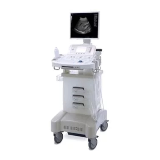
INTRODUCTION The SONIX CEP Ultrasound System is a software driven, ergonomic, diagnostic medical device. It uses state of the art technologies to acquire, process and display ultrasound data (Figure 1-1). The system has five (5) major field serviceable components: LCD display, Console, Ultrasound Modulo, Transducers and UPS. -
Page 14: Physical Description
1.7.5 SONIX CEP is delivered with a Sola/Hevi-Duty S4K2U700, 120V (volt) UPS from EGS Electrical Group, LLC. The UPS is tucked underneath the SONIX with the necessary controls available from a panel at the bottom front of the system. The UPS battery has a limited power supply When the system is running on battery power it cannot be left unplugged for long periods. -
Page 15: Chapter 2: System Specifications
CHAPTER 2: SYSTEM SPECIFICATIONS DIMENSION Table 2-1: System Dimensions Measurement Metric Value US Value Width 53 cm 21.0 in Depth 71.0 cm 28.0 in Height 142.0 cm – 155.0 cm 56.0 in – 61.0 in Weight 101.8 kg 224.0 lbs SYSTEM ARCHITECTURE •... -
Page 16: Clinical Applications
CLINICAL APPLICATIONS • Abdominal (Aorta) • Biliary • Bladder • Cardiac • Early OB • F(oreign) Bodies • L(ower) Extremity • Late OB • Other • Pelvic • Procedure • Renal • Thoracic • Trauma/FAST • V(ascular) Access TRANSDUCERS • PA4-2/20 broadband (2.8 MHz) N/A phased array •... -
Page 17: Image Parameter Adjustments
IMAGE PARAMETER ADJUSTMENTS 2.6.1 B Mode • Gain • • Focus • Dynamic Range • Color Maps • Line Density • Sector Size • Steer • Acoustic Power • Wide Sector • Zoom 2.6.2 M Mode • Sweep Speed • Sample Volume 2.6.3 Pulsed Wave Doppler... -
Page 18: Clinical Analysis
CLINICAL ANALYSIS • Measurement Types: • Distance • Continuous Trace • Trace By Points • Ellipse Area • Doppler Acceleration • Doppler Average Velocity • Doppler Trace • M Mode Distance • Time • E-Med Worksheets • Custom calculation packages •... - Page 19 • L(ower) Extremity (Basic Measurements Package) • Distance <|> • Area <|> • Diam Red <|> • Area Red • Hip Angle • 3Dist.Volume • Late OB • • • • • Other (Basic Measurements Package) • Distance <|> • Area <|>...
-
Page 20: Image Storage
• Thoracic (Basic Measurements Package) • Distance <|> • Area <|> • Diam Red <|> • Area Red • Hip Angle • 3Dist.Volume • Trauma (FAST) • AA AP Dia • V(ascular) Access (Basic Measurements Package) • Distance <|> • Area <|>... -
Page 21: External Connections
2.10 EXTERNAL CONNECTIONS • Parallel Port • Serial Port • USB (Universal Serial Bus) Port (5 Ports) • Video IN/OUT • Audio IN/OUT • PS/2 (2 Connectors) • Ethernet (Hardwired) • SONIX Live (streaming video) compatible • Modem • BNC (Bayonet Neill Concelman) Connector (2 Connectors) •... -
Page 22: Additional Hardware Features
7A/250V SLO-BLO Fuse Size 6.4mm x 31.8mm 2.15 VOLTAGE The SONIX CEP is delivered to customers with the voltage already adjusted to the correct setting for the North American market: 110V. Chapter 2: System Specifications 00.053.008, Revision B CEP Service Manual... -
Page 23: Chapter 3: System Installation
Operate in an indoor environment only, free from moisture, flammable liquids, gases, corrosive substances, strong electrical or magnetic fields and equipment that generates high frequency waves. Ultrasonix cannot guarantee the proper performance of the SONIX CEP if used in the above-listed conditions. Table 3-2: Barcode Reader Operating Temperature 32º... -
Page 24: Electrical Requirements
Refer to OEM peripheral manuals for peripheral-specific electrical ratings. Warning: If the SONIX CEP utility supply voltage exceeds the acceptable range, the internal circuitry protection feature will not allow the system to power up nor will it allow the battery to charge. -
Page 25: Electrostatic Discharge
3.1.3 Electrostatic Discharge During normal operation, the presence of electrostatic discharge (ESD) can cause system reliability issues. The following are the most common causes for ESD: • Moving people • Low humidity • Improper grounding • Unshielded cable • Poor connection •... -
Page 26: Electromagnetic And Radio Frequency Interference
3.1.4 Electromagnetic and Radio Frequency Interference This equipment has been tested and found to comply with the EMC limits for the Medical Device Directive 93/42/EEC (EN 55011 Class 1 and EN 60601-1-2). These limits are designed to provide reasonable protection against harmful interference in a typical medical installation. The equipment generates, uses and can radiate radio frequency (RF) energy and if not installed and used in accordance with these instructions, may cause harmful interference to other devices in the vicinity. - Page 27 Table 3-7: EN 60601-1-2:2001 (Table 202) Guidance and Manufacturer’s Declaration—Electromagnetic Immunity SONIX Ultrasound Systems are intended for use in the electromagnetic environment specified below. The customer or the user of the SONIX Ultrasound System should ensure that it is used in such an environment.
- Page 28 Table 3-8: EN 60601-1-2:2001 (Table 204) Guidance and Manufacturer’s Declaration—Electromagnetic Immunity The SONIX is intended for use in the electromagnetic environment specified below. The customer or the user of the SONIX should ensure that it is used in such an environment. Immunity IEC 60601 Compliance...
- Page 29 Table 3-9: EN 60601-1-2:2001 (Table 206) Recommended Separation Distances Between Portable and Mobile RF Communications Equipment and the SONIX The SONIX is intended for use in an electromagnetic environment in which radiated RF disturbances are controlled. The customer or the user of the SONIX can help prevent electromagnetic interference by maintaining a minimum distance between portable and mobile RF communications equipment (transmitters) and the SONIX, as recommended below, according to the maximum output power of the communications equipment.
-
Page 30: Wiring Requirements
The SONIX CEP networking options are intended for use inside your organization's firewall. Organizations that elect to configure/use the networking functionality provided by Ultrasonix are assuming all liabilities and risks associated with that decision. 3.1.5.3 Image Management Network Obtain the following information from the system administrator: •... -
Page 31: System Installation
Examine the "Tip and Tell" attachment on the outside of the package to ensure the crate has not been tipped too far during transport and delivery. "Tip and Tell" = Acceptable "Tip and Tell" = Unacceptable Report any damage to both the carrier and Ultrasonix. CEP Service Manual 00.053.008, Revision B Chapter 3: System Installation... -
Page 32: Uncrating Instructions
Before uncrating the system, ensure there is adequate room for removing it from its packaging. The space should be at least equivalent to the crate's overall dimensions. To Uncrate the SONIX CEP System: Cut and remove the four (4) ¼” nylon straps around the box. - Page 33 Remove the white foam "ramps" from either side of the system. Unfold the cardboard box and remove the supporting foam underneath each side of the system. Using the pre-cut slit in the white foam ramps, insert them onto the folded cardboard and align them with the wheels.
-
Page 34: Mounting The Arm For The Lcd Display
3.2.3 Mounting the Arm for the LCD Display Equipment/Tools Required: • 4mm Allen key (provided, in LCD display box). Note: Be sure to uncrate the system first (see 3.2.2 Uncrating Instructions for details). To Mount the Arm for the LCD Display: Open and unpack the box containing the LCD display. - Page 35 Install the LCD display arm onto the tower. Hand-tighten the screw for the LCD display arm using the 4mm Allen Key provided with the system. CEP Service Manual 00.053.008, Revision B Chapter 3: System Installation...
-
Page 36: Mounting The Lcd Display
3.2.4 Mounting the LCD Display Figure 1–1: LCD Display Assembly To Mount the LCD Display: Adjust the base of the LCD display until its support faces back and the front faces forward. Rest the LCD Display on its support. Fasten the LCD display to the support arm with the four (4) thumbscrews (provided in the box with the LCD display). -
Page 37: System Case Connectivity Panel Check
USB ports to connect the barcode reader. Take care to ensure that the cord does not tangle. USB ports (2) Used by the LCD display and wireless adapter. Line-in – may be used to connect an Ultrasonix-approved audio input device. Sound connections System Speaker connection. System Microphone connection. Disabled. - Page 38 VGA monitor. Refer to item 14, below. Digital Video DVI video output May be used to connect an Ultrasonix-approved RS232 serial device. RS232 Serial Port Note: In the event that the UPS must be programmed in the field, use of this RS232 Serial Port will be required.
-
Page 39: Back Connectivity Panel
The SONIX system provides 2 USB ports and a CD/DVD writer at the front of the operator console. These 2 USB Ports can be used to connect Ultrasonix-approved USB devices such as USB thumb drives to the system for image file transfer. -
Page 40: Rear Console Connectivity (Cep Barcode Reader)
3.2.9 Fuses The diagram below shows the location of the EMI Filter which houses the SONIX CEP fuses. Refer to 3.2.10 Changing Fuses for details on how to remove the fuse box and replace the fuse(s). Figure 3-5: Voltage Adjustment Devices... -
Page 41: Changing Fuses
To Change the Fuse: Make sure the UPS is powered down and the system completely turned off. Unplug the SONIX CEP from the wall socket and remove the rear shroud (refer to 8.4.3 Accessing the System Case for details). Use the screwdriver to open the fuse box lid. -
Page 42: Ups
Technicians and customers are forbidden from opening the UPS. Attempting to open the UPS may cause exposure to lethal voltages. Should the UPS require maintenance or replacement, only qualified Ultrasonix Service Technicians may perform service as detailed in this Service Manual. -
Page 43: Powering The Ups On And Off
To Power OFF the UPS: Note: When the UPS is off, the SONIX CEP will not run even if it is plugged into an AC power source. On the SOLA panel at the bottom front of the system, press and hold the STANDBY button for one (1) second. -
Page 44: Connecting The Barcode Reader
Technicians and customers are forbidden from opening the barcode reader. Attempting to open the barcode reader may cause exposure to hazardous laser light. Should the barcode reader require maintenance or replacement, only qualified Ultrasonix Service Technicians may perform service as detailed in this Service Manual. -
Page 45: Sonix Op/Sp
Plug the barcode reader's USB connector into one of the USB ports at connection 7 on the SX1.0 or SX1.1 System Case Connectivity Panel (for details, refer to Figures 9-1 and 9-2, respectively, in the SONIX CEP User Manual). Note: To keep the barcode reader handy, store it in one of the smaller transducer holders. - Page 46 Attempting to open the cable reel may cause physical injury and/or exposure to lethal voltages. Should the cable reel require maintenance or replacement, only qualified Ultrasonix Service Technicians may perform service as detailed in this Service Manual. Caution:...
-
Page 47: Wireless Connection
3.2.15 Wireless Connection Mount and configure the SONIX CEP wireless adapter during system installation. Each adapter is delivered with a bracket and two (2) set screws which are used to gently tighten the adapter in the bracket so it cannot move once it is secured. - Page 48 To Attach the Wireless Adapter to the SONIX OP/SP: Ensure the wireless adapter has been gently secured in the wireless bracket. Note: Tighten the set screws with the #2 Allen Key (provided in bag with thumbscrews). Remove the bottom left thumbscrew on the back of the LCD display. Place the screw hole of the prepared wireless bracket over the thumbscrew mounting position and reattach the thumbscrew through the bracket.
-
Page 49: Final Inspection
If possible, the UPS should be fully charged before completing the Inspect the system for scratches or damage. Note any damage to the system and report it to Ultrasonix. Plug main AC to primary power connector. Turn on the system. - Page 50 Chapter 3: System Installation 00.053.008, Revision B CEP Service Manual...
-
Page 51: Chapter 4: Performance Testing
CHAPTER 4: PERFORMANCE TESTING INTRODUCTION This section describes the various tests performed on the system immediately following installation, updating and repair. The purpose of performance testing is to verify the correct operation of system (hardware, software and mechanical). During these tests, the system should be running in normal operating mode. -
Page 52: Image Test
• Doppler Gain • PRF • Doppler Frequency 1. Optimization Mode • WF 2. Sector Size/Zoom Doppler Modes • Sweep Angle 3. Optimization Mode DR • Sweep 4. Wide Mode • Gate • Live Mode • TGC • Annotation • Probe Selection •... -
Page 53: Communication Test (Hard-Wired)
To Perform a LAN Communication Test: Press the console QSONIX button. Online Support Select . This should connect the system to an Ultrasonix Technical Support Representative. Note: It may be necessary to restart in order for these changes to take affect. CEP Service Manual 00.053.008, Revision B... -
Page 54: Dialup Communication Test (Hard-Wired)
To Perform a Dialup Communication Test: Press the console QSONIX button. Online Support Select . This should connect the system to an Ultrasonix Technical Support Representative. Note: While the system is dialing out, the current dialing status to your ISP will be displayed. -
Page 55: Communication Test (Wireless)
COMMUNICATION TEST (WIRELESS) Refer to section 3.2.15 Wireless Connection for details on setting up the wireless adapter. Figure 4-3: Network Configuration Page Figure 4-4: Wireless Network Connection Setup Wireless Signal Strength Indicator Security Indicator CEP Service Manual 00.053.008, Revision B Chapter 4: Performance Test... - Page 56 To Perform a Wireless Communication Test: Press the console QSONIX button. Online Support Select . This should connect the system to an Ultrasonix Technical Support Representative. Note: It may be necessary to restart in order for these changes to take affect. Chapter 4: Performance Test 00.053.008, Revision B...
-
Page 57: Removable Hardware Test
Move the system around to check that the casters rotate properly. Note: The SONIX CEP will be more difficult to move around on carpeting due to increased friction on the casters. Finally, rotate and adjust the operator console. Press all buttons and toggles to ensure that none are in a locked position. -
Page 58: Ups Test
UPS TEST To Test the UPS: Ensure that the UPS has been powered on (section 1.8 UPS). Ensure the system is plugged in and powered on. Unplug the system's AC connection from the wall. Ensure the UPS On and Battery LEDs are lit and the system is still running (i.e., the system is running on battery power. -
Page 59: Chapter 5: Software
CHAPTER 5: SOFTWARE SOFTWARE MODES The SONIX CEP comes equipped with many modes of operations. Please refer to the SONIX CEP User Manual for complete details. SOFTWARE UPDATE VIA THE INTERNET To Update via the Internet: Press the console MENU button. -
Page 60: System Recovery
Representative for further instructions. SYSTEM RECOVERY Before performing a system recovery on the system, please consult an Ultrasonix Technical Support Representative as this should only be done as a last resort. Technical Support will provide you with the appropriate documentation to carry out a system recovery. -
Page 61: Chapter 6: Connect Peripherals
CHAPTER 6: CONNECT PERIPHERALS B&W/COLOR THERMAL PHOTO PRINTER OR VCR The SONIX CEP supports a variety of thermal printers. It also supports a VHS recorder (refer to the Ultrasonix price list for specific makes and models). Note: Connectivity Panel In the , the video splitter’s green plug is for B&W and the blue plug is for Color. -
Page 62: Remote Trigger
REMOTE TRIGGER To Connect the Remote Trigger Cable: Connectivity Panel Print BNC Open the lid to the and find the plug (connection point 19 in Figure 3-1 and Error! Reference source not found.). Connect one end of the Remote Trigger cable here. -
Page 63: Inkjet Or Laser Printer Setup
Note: These instructions can also be used as a reference for installing other printers to the SONIX CEP. To Connect the HP DeskJet 5440 directly to the SONIX (Local Printer): Ensure the SONIX has been powered on and is running. - Page 64 USB) from the drop down menu. Click Next. Find the HP Deskjet 5400 series disc that came with the printer and put it in the CD-ROM drive on the SONIX CEP console. Have Disk Select , then click on Browse….
- Page 65 To Configure a Print Key for Paper Printing: Press the console MENU button. Administrator Print Key Click on > Select the desired Print Key tab: Print 1 Print 2 Print 3 Note: Each of the three (3) tabs corresponds to one of three (3) buttons on the PRINT console.
-
Page 66: Network Printer Setup: Hp Deskjet 5440
6.3.2 Network Printer Setup: HP DeskJet 5440 Note: This section is meant to be used only as a guide as not all networks are identical. These instructions can also be used as a reference for installing other SONIX network printers. To Connect the HP DeskJet 5440 directly to the SONIX (Network Printer) Note: Before proceeding, ensure that the network has a shared printer. - Page 67 To Configure a Print Key for Paper Printing: Press the console MENU button. Administrator Print Key Click on > Select the desired Print Key tab: Print 1 Print 2 Print 3 Note: Each of the three (3) tabs corresponds to one of three (3) buttons on the PRINT console.
-
Page 68: Image Sheet Printing
6.3.3 Image Sheet Printing To Configure Image Sheet Printing: Press the console MENU button. Administrator Peripherals Click on > From the Paper Printer tab, under Image Sheet Printing click the Enable check box. Columns Rows Configure the as required. Note: The default setting prints two (2) Columns and three (3) -
Page 69: Chapter 7: Components And Assembly
The component drawings are divided into categories for easier access. In many cases, each component is followed by a brief description and its location within the system. When service is preformed by Ultrasonix Technical Support, component label names will be used to avoid any discrepancies. ASSEMBLY DRAWINGS 7.2.1... - Page 70 Chapter 7: Components and Assembly 00.053.008, Revision B CEP Service Manual...
- Page 71 CEP Service Manual 00.053.008, Revision B Chapter 7: Components and Assembly...
-
Page 72: Module Assembly
7.2.2 Module Assembly Figure 7-2: Modulo Assembly Drawings Chapter 7: Components and Assembly 00.053.008, Revision B CEP Service Manual... - Page 73 CEP Service Manual 00.053.008, Revision B Chapter 7: Components and Assembly...
-
Page 74: Cart Assembly
7.2.3 Cart Assembly Figure 7-3: Cart Assembly Drawings Chapter 7: Components and Assembly 00.053.008, Revision B CEP Service Manual... - Page 75 CEP Service Manual 00.053.008, Revision B Chapter 7: Components and Assembly...
- Page 76 Chapter 7: Components and Assembly 00.053.008, Revision B CEP Service Manual...
- Page 77 CEP Service Manual 00.053.008, Revision B Chapter 7: Components and Assembly...
-
Page 78: Electrical Components
ELECTRICAL COMPONENTS This section illustrates the various custom PCBs and main power components that are used. Table 7-1: Ultrasonix Custom PCBs Component Name: ECHO US Module Board` Description: 12 Layers PCB. This board uses state of the art technology. Image modes are downloaded in a fraction of a second due to the advanced FPGAs and DSPs. - Page 79 Table 7-2: Power Management Components Component Name: Isolation Transformer Description: Medical Grade Isolation Transformer is used to stabilize the input voltage. Dimension: 6.5” Diameter Color: Component Name: Auto-Switching Power Supply Description: PC power supply that auto switches between 100V— 130V and 200V—240V. Dimension: 6”...
-
Page 80: Cable Components
7.3.1 Cable Components This section shows the cables inside the SONIX, such as the ones on back of the ultrasound modulo and the ones from the console to the ultrasound modulo. Figure 7-4: SONIX System Cable Components Chapter 7: Components and Assembly 00.053.008, Revision B CEP Service Manual... - Page 81 CEP Service Manual 00.053.008, Revision B Chapter 7: Components and Assembly...
- Page 82 Chapter 7: Components and Assembly 00.053.008, Revision B CEP Service Manual...
- Page 83 CEP Service Manual 00.053.008, Revision B Chapter 7: Components and Assembly...
- Page 84 Figure 7-5: CEP-Specific Cable Components Chapter 7: Components and Assembly 00.053.008, Revision B CEP Service Manual...
-
Page 85: Peripheral Components
The 1-position AC peripheral power cable is located in the modulo utility panel area and can be accessed via the peripheral shelf door of the SONIX System. The connector is clearly labeled with “For use with Approved Ultrasonix Peripherals only” and is to be used for connecting third- party peripherals to the SONIX system. - Page 86 Chapter 7: Components and Assembly 00.053.008, Revision B CEP Service Manual...
-
Page 87: Chapter 8: Field Service Components
CHAPTER 8: FIELD SERVICE COMPONENTS INTRODUCTION This section describes how to service the five (5) field serviceable components: LCD display, console, ultrasound modulo, transducers and UPS. LCD DISPLAY SERVICING 8.2.1 Removing the Liquid Crystal Display (LCD) Display Figure 8-1: LCD Display (Rear View) Power Cable DVI Cable Thumbscrews... -
Page 88: Installing The Liquid Crystal Display (Lcd) Display
8.2.2 Installing the Liquid Crystal Display (LCD) Display To Install the LCD Display: Place the LCD display in position. Install and tighten the four (4) thumbscrews that hold the LCD display in place. Note: If a wireless adapter is in use, leave off the lower left thumbscrew. Reconnect the Power, DVI and USB cables to the LCD display. -
Page 89: Replacing The Lcd Display Cables (Sx3.0)
8.2.3 Replacing the LCD Display Cables (SX3.0) Equipment/Tools Required: • #1 Phillips screwdriver • #2 Phillips screwdriver • 10mm socket wrench. To Replace the SX 3.0 LCD Display Cables: Power off the SONIX system. Power down the UPS (3.2.11.1 Powering the UPS ON and OFF). Unplug it from the power outlet. - Page 90 Use the #1 Phillips screwdriver and detach the two (2) screws (17) securing the painted upper shroud and CM Neoflex Cableway (16). In order to remove the Neoflex Arm from the CM Neoflex Upper Mount assembly (11), use the 10mm wrench to remove the four (4) Plate Screws (14) and four (4) M5 Split Lock washers (13).
- Page 91 Loosen the set screw (15) and remove the CM Neoflex Upper Mount Assembly and Pipe (11 and 12). Note: The set screw only needs to be loosened, not removed. Use a #2 Phillips screwdriver and remove the two (2) Phillips head screws (3). Lift off the CM Utility Panel Shield (2).
- Page 92 Use the 10mm wrench and remove the four (4) washers and plate screws (5 and 6) to detach subassembly (A) from the cart (B). Use the 10mm wrench and remove the four (4) washers and plate screws (5 and 6) to detach the CM Neoflex Lower Mount (7) from the CM Neoflex Adapter (4).
-
Page 93: Console Servicing
CONSOLE SERVICING 8.3.1 Removing the Console Equipment/Tools Required: • #2 Phillips screwdriver • 10mm wrench • 2.5mm Allen key. To Remove the Console: Power off the SONIX system and unplug it from the power outlet. Under the console, remove the left inner shroud (9) using a #2 Phillips screwdriver on the four (4) screws (10) at the top and a 2.5mm Allen key to undo the one (1) fastening (8) on the right-hand side. - Page 94 Use the 10mm socket wrench to remove the bolt that grounds the console wiring harness to the modulo. Use the 10mm socket wrench to remove the four (4) bolts/washers from underneath the console. Note: The front two (2) bolts also secure the Front Handle (6). Carefully pull the console up off the mounting plate, while feeding the cable up.
-
Page 95: Installing The Console
8.3.2 Installing the Console Equipment/Tools Required: • #2 Phillips screwdriver • 10mm wrench • 2.5mm Allen key • non-permanent glue. To Install the Console: Feed the cable through the opening at the top of the assembly. Plug the cables into the module through the access panel. Plug in the system. -
Page 96: Ultrasound Modulo Servicing
USB Memory stick or removable disk. To Back-up User Data/Presets: Power on the SONIX CEP and wait until the system is fully loaded. Plug a USB Memory Stick or any removable disk into one of the USB ports at the front of the console. -
Page 97: Back-Up Patient Data (As Required)
Blank CD or DVD • USB key or drive. To Back-up Patient Data: Power on the SONIX CEP and wait till the system fully loads. Press the console ID button. Review Select the patient(s) to be backed up and click the button. -
Page 98: Removing The Rear Shroud (Accessing The System Case)
8.4.3 Removing the Rear Shroud (Accessing the System Case) This step is necessary in order to complete several different service activities, including removing the modulo, accessing the modem, replacing speaker cables and removing the UPS. Equipment/Tools Required: • 4mm Allen key. To Remove the Rear Shroud: Power down the UPS (3.2.11.1 Powering the UPS ON and OFF). -
Page 99: Removing The Ultrasound Modulo
Undo the modem connection and remove the modem from the back of the modulo. Note: Due to the number of connections involved in steps 1, 2 and 3, Ultrasonix recommends marking the location of all unlabeled wires/cables by labeling them with masking tape. - Page 100 Using the 10mm wrench, remove the four (4) bolts holding the modulo support arms. Note: Only two (2) bolts are visible in this picture. Both have two (2) bolts each, in mirror image positions. Be sure to remove all four (4). Loosen the two (2) bolts holding the modulo support arms upright, allowing them to lean down out of the way.
-
Page 101: Installing The Ultrasound Modulo
(8) (green). 8 and 11 Note: At position ( ), there is also a connection available for an Ultrasonix-approved audio input device (blue). Note: The numbers displayed above in the figure and table above correspond to the numbers in Figure 3-1 and Error! Reference source not found.. - Page 102 Connect all cables from the console and tower. Looking from the back of the SONIX, the cables are connected as in Figure 8-2: Modulo Cable Connections (above). Note: Connect the Ultrasonix labeled cables first. The connection points of the temporarily labeled cables will then become self-evident. Connect all cables to the power supply and modulo.
-
Page 103: Removing The Front Block
8.4.6 Removing the Front Block Equipment/Tools Required: • #2 Phillips screwdriver. To Remove the Front Block: To open the Front Block, remove the two (2) screws (pictured below). Note: Although not shown, there will be a service access sticker to indicate the correct screws. -
Page 104: Replacing The Front Block
To remove the door, undo the four (4) screws attached to the hinge. The two (2) screws on the top hinge are marked below. The Front Block can now be removed. 8.4.7 Replacing the Front Block Equipment/Tools Required: • #2 Phillips screwdriver To Replace the Front Block: Attach the new Front Block via the hinge with the four (4) hinge screws. - Page 105 The black and multi-colored plugs can be connected in any order. Connect the power cable coming from the PCI card (3) to the plug on the right-hand side of the door. While closing the Front Block, tuck the cables in, particularly the power cable (3) so that they do not hit the fans on the left and right side of the SONIX.
-
Page 106: Replacing The Rear Shroud
Pull the power cord out from under the system and plug it into a wall socket. Power on the UPS (3.2.11.1 Powering the UPS ON and OFF). Power on the SONIX CEP system. Chapter 8: Field Service Components 00.053.008, Revision B... -
Page 107: Transferring User Settings
8.4.9 Transferring User Settings Once the new ultrasound modulo has been installed, import the previously-saved user settings from the removable disk to this system. Equipment/Tools Required: • USB Memory stick or removable disk containing previously exported Patient data. To Transfer User Data: Power on the SONIX system and wait till the system fully loads. -
Page 108: Re-Import License.key (If Required)
License.Key 8.4.10 Re-Import (If Required) In general, it will not be necessary to reinstall license keys as the ultrasound modulo will have the license keys pre-installed. However, if the customer purchased optional license keys, re- issuing the additional licenses may be required. Refer to Chapter 11: License.Key Importation for details on re-importing license.key, REPLACING THE SPEAKER POWER CABLE To Replace the Speaker Power Cable:... -
Page 109: Replacing The Modem
REPLACING THE MODEM To Replace the Modem: Remove the rear shroud (8.4.3 Accessing the System Case) to expose the modem. Modem Undo the modem connection and remove the modem from the back of the modulo. Remove the modem and replace it with a new one. Reconnect the modem. -
Page 110: Ups Servicing
UPS SERVICING The OEM User's Guide for the UPS is shipped with the SONIX CEP system. Be sure to read and follow all the Cautions and Warnings. Very little UPS servicing can be accomplished in the field. The exception to this is UPS programming. In the rare cases where the UPS may have to be reprogrammed in the field, Ultrasonix Technical Support will provide you with a copy of the appropriate documentation. -
Page 111: Removing/Replacing The Ups
8.7.2 Removing/Replacing the UPS Equipment/Tools Required: • 3mm Allen key. To Remove the UPS: Power the UPS off as per section 3.2.11.1 Powering the UPS ON and OFF. Unplug the power cord from the wall outlet. Remove the rear shroud following the instructions in 8.4.3 Accessing the System Case. Disconnect all the cables running to the UPS. - Page 112 To Replace the UPS: Ensure the rear shroud has been removed (per the instructions in 8.4.3 Accessing the System Case). Gently slide the new UPS into its slot. Using the 3mm Allen key, tighten the two (2) set screws securing the UPS. Connect the UPS cables.
-
Page 113: Barcode Reader Servicing
BARCODE READER SERVICING The barcode reader is configured to SONIX CEP requirements prior to shipping with the system. If it becomes necessary to reconfigure it in the field, Ultrasonix Technical Support will provide you with a copy of the appropriate documentation. -
Page 114: Attaching/Detaching The Cable Reel
8.9.1 Attaching/Detaching the Cable Reel Equipment/Tools/Personnel Required: • Two (2) people • 13mm socket wrench • #1 or2 Phillips screwdriver. To Replace the Cable Reel: Power the UPS off as per section 3.2.11.1 Powering the UPS ON and OFF. Unplug the power cord from the wall outlet. Remove the rear shroud following the instructions in 8.4.3 Accessing the System Case. -
Page 115: Transducer Servicing
8.10 TRANSDUCER SERVICING Ultrasound transducers are highly sensitive medical equipment requiring proper care and cleaning. There are two possible sources when a client is experiencing image problems: • transducer • ultrasound modulo’s transducer MUX board. 8.10.1 Testing the Transducer To Test a Transducer: Ensure the transducer is plugged in to the SONIX and has been selected via the console PROBE button. -
Page 116: Transducer Maintenance
8.11 TRANSDUCER MAINTENANCE 8.11.1 Guidelines Ultrasonix recommends inspecting the transducers prior to each use. • Ensure the transducers are always clean before they are used. There must be no ultrasound gel (from previous imaging), any debris, films or unusual odors present. -
Page 117: Cleaning/Disinfecting Recommendations And Warnings For All Non-Invasive Transducers
Use of these chemicals will cause damage to your transducer. DO NOT use sterilization or disinfections methods that have not been recommended by Ultrasonix. Severe damage will result. Please contact Ultrasonix if you have any doubt about sterilization or disinfection methods. Warning: Any transducer suspected of being contaminated with Creutzfeld Jacob disease material cannot be cleaned or sterilized. -
Page 118: Cleaning (Non-Invasive Transducers)
8.11.3.1 Cleaning (Non-Invasive Transducers) To Clean the Transducer: After every patient exam, wipe the ultrasound transmission gel off the transducer. Wipe the transducer and cable with a soft, dry or water-moistened cloth. Wipe the transducer with either: • a recommended disinfectant (refer to Table 8-3) •... -
Page 119: Maintenance (Non-Invasive Transducers)
Ultrasonix. DO NOT use sterilization or disinfection methods that have not been recommended by Ultrasonix. Severe damage will result. Please contact Ultrasonix if you have any doubt about sterilization or disinfection methods. Use of non-recommended cleaning agents may cause damage to the housing and will void transducer warranties. -
Page 120: Storing And Packaging (Non-Invasive Transducers)
Avoid transducer contact with strong solvents such as acetone, freon and other industrial cleansers. DO NOT use sterilization or disinfection methods that have not been recommended by Ultrasonix. Severe damage will result. Please contact Ultrasonix if you have any doubt about sterilization or disinfection methods. Warning: Any transducer suspected of being contaminated with Creutzfeld Jacob disease material cannot be cleaned or sterilized. -
Page 121: Cleaning (Invasive Transducers)
8.11.4.1 Cleaning (Invasive Transducers) Disinfect the transducer prior to the first exam and every exam thereafter. To clean the transducer: Unplug the transducer. Wash the transducer head and cable with soap and water to remove any protein buildup; however do not rinse or immerse the transducer near the strain relief. Disinfect the transducer with one of disinfectants listed below: •... -
Page 122: Maintenance (Invasive Transducers)
Ultrasonix. DO NOT use sterilization or disinfection methods that have not been recommended by Ultrasonix. Severe damage will result. Please contact Ultrasonix if you have any doubt about sterilization or disinfection methods. Use of non-recommended cleaning agents may cause damage to the housing and will void transducer warranties. -
Page 123: Storing And Packaging (Invasive Transducers)
Photocopy the form on page 114, complete it, and include it on the OUTSIDE of the shipping box or package Ultrasonix will not open the package until this form is checked by our Receiving Department. CEP Service Manual 00.053.008, Revision B... - Page 124 TRANSDUCER DISINFECTION CERTIFICATE This is to certify that the transducer(s) in this shipment has been disinfected as per the relevant instructions in sections of the SONIX CEP Service Manual. 8.11.3.2 8.11.4.2 Please photocopy, complete and include this form on the OUTSIDE of the shipping box or package.
-
Page 125: Chapter 9: Dicom Configuration
CHAPTER 9: DICOM CONFIGURATION DICOM The system uses the Digital Imaging and Communications in Medicine ( ) standard to share medical DICOM information with other digital imaging systems. The SONIX system, by means of the protocol, communicates with Storage Print Modality Worklist Service Class Providers. -
Page 126: Dicom Storage Configuration
DICOM STORAGE CONFIGURATION DICOM Storage Settings dialog offers basic and advanced settings for configuring the SONIX system for DICOM Image Storage. Figure 9-1: DICOM Configuration – DICOM Storage To Configure the DICOM Storage Setting: Press the console MENU button. Administrator DICOM Select >... - Page 127 DICOM Storage Application Entity (AE) Configuration Application dialog enables configuration of Entity properties. Figure 9-2: DICOM Storage Settings – AE Configuration Table 9-1: DICOM Storage Settings – AE Configuration Settings Local Host Properties – Service Class User(SCU) – SONIX system Application Entity Title AE Title of the SONIX system.
- Page 128 DICOM Storage Settings dialog specifies how images are stored. Figure 9-3: DICOM Storage Settings – Storage Settings Table 9-2: DICOM Storage Settings – Storage Settings Store Grayscale Images Select to store images in grayscale format. Select to swap the color components of the image pixel data – the blue Convert BGR to RGB colors are swapped with the red colors.
- Page 129 DICOM Storage Brightness/Contrast dialog changes the brightness and contrast settings. These settings are applied to the images that are sent to the SCP not the images stored locally. Before After The effects of these settings can be seen in the images.
- Page 130 DICOM Storage Commitment dialog enables configuration of the Storage Commitment AE. Check " Turn on Storage Commitment " to enable Storage Commitment feature. Figure 9-5: DICOM Storage Settings – Storage Commitment Table 9-4: DICOM Storage Settings – Storage Commitment Turn on Storage Commitment Storage Commitment Select to enable functionality.
-
Page 131: Dicom Print Configuration
DICOM PRINT CONFIGURATION DICOM Print Settings DICOM offer basic and advanced settings for configuring the SONIX system for Print Figure 9-6: DICOM Configuration – DICOM Print To Configure DICOM Print Settings: Press the console MENU button. Administrator DICOM Select > Turn on DICOM Print Settings Check "... - Page 132 DICOM Print AE Configuration Application Entity dialog enables configuration of properties. Figure 9-7: DICOM Print Settings – AE Configuration Table 9-5: DICOM Print Settings – AE Configuration Local Host Properties – SCU (SONIX System) Application Entity Title AE Title of the SONIX system. Port Listening port of the SONIX system (unused).
- Page 133 DICOM Print Settings dialog enables configuration of general print properties. Figure 9-8: DICOM Print Settings – Print Settings Table 9-6: DICOM Print Settings – Print Settings Select to print images in color, otherwise they are printed in grayscale. Default is Print in Color unchecked (print in grayscale).
- Page 134 Advanced Print Settings dialog enables configuration of advanced printing. Figure 9-9: DICOM Print Settings – Advanced Print Settings Table 9-7: DICOM Print Settings – Advanced Print Settings Orientation Select the orientation of the print page. Size Select the size of the print page. Magnification Select the method of magnification used.
- Page 135 DICOM Print Brightness/Contrast Brightness Contrast dialog changes the settings. These settings are applied to the images that are sent to the SCP, not the images stored locally. Before After The effect of these settings can be seen in the images. Figure 9-10: DICOM Print Settings –...
-
Page 136: Dicom Worklist Configuration
DICOM WORKLIST CONFIGURATION DICOM Worklist Settings DICOM Worklist SCU offer advanced settings for configuring the (Service Class User). Figure 9-11: DICOM Configuration – DICOM Worklist To Configure DICOM Worklist Settings: Press the console MENU button. Administrator DICOM Select > Check " Turn on DICOM Worklist ", then select the associated Settings... - Page 137 DICOM Worklist AE Configuration Application Entity dialog enables configuration of properties. Figure 9-12: DICOM Worklist Settings– AE Configuration Table 9-9: DICOM Worklist Settings – AE Configuration Local Host Properties – SCU (SONIX System) Application Entity Title AE Title of the SONIX system. Port Listening port of the SONIX system (unused).
- Page 138 Chapter 9: DICOM Configuration 00.053.008, Revision B CEP Service Manual...
-
Page 139: Chapter 10: Network Connection
Note: Before attempting to configure the Network connection, ask the IT department for the correct Transmission Control Internet Protocol/Internet Protocol (TCP/IP) settings for the SONIX CEP system. Figure 10-1: Network Configuration Dialog 10.1 SETTING UP THE NETWORK To Configure Network Settings: Press the console MENU button. -
Page 140: Wireless Settings
> > Wireless Configure the wireless connection following the onscreen directions in the Network Connection dialog. Note: Wireless Network Connection options are controlled by MS Windows, not Ultrasonix. Chapter 10: Network Connection 00.053.008, Revision B CEP Service Manual... -
Page 141: Remote Support
10.2 REMOTE SUPPORT Remote support allows Ultrasonix Technical Support to view and control the SONIX for diagnostic purposes. Note: A network connection is required for DICOM image transfer and on-line chat support. To Configure Remote Support: Press the console MENU button. - Page 142 Chapter 10: Network Connection 00.053.008, Revision B CEP Service Manual...
-
Page 143: Chapter 11: License.key Importation
Make note of the shown in the window and forward it to Ultrasonix Technical Support to obtain a license.key file. When the license.key file arrives, copy it to a USB Memory stick. D: Drive Copy and paste the new license.key file onto the... -
Page 144: Re-Import License.key From A Local Drive
Look in Local Disk (D:) Under the drop-down menu, select and locate license.key. Open Click to re-import license.key. Note: If there are any problems, contact Ultrasonix Technical Support for assistance. Chapter 11: License Key Importation 00.053.008, Revision B CEP Service Manual... -
Page 145: Chapter 12: Complete Plastics Replacement
CHAPTER 12: COMPLETE PLASTICS REPLACEMENT 12.1 INTRODUCTION This section describes how to disassemble the systems plastic covers or shrouds. Equipment/Tools Required: • 2.5mm Allen key • 4mm Allen key • 5mm Allen key • #1 Phillips screwdriver • #2 Phillips screwdriver •... -
Page 146: Console Support Plastics Removal
12.3 CONSOLE SUPPORT PLASTICS REMOVAL Removing the console support plastics is a two (2) part process. Both the inner (section 12.3.1) and outer (section 12.3.2) segments must be removed. 12.3.1 Inner Console Support and Console Assembly Plastics Removal To Remove the Inner Console Support: To remove the Left Inner Console Support Plastic (1) from the assembly, remove the four tap caps (2) off the screws located at the top. - Page 147 Remove the Cart Hinge Plastic (6) from the assembly by removing the four screws (7). To detach the console assembly (8), remove two (2) screws at the rear of the tech board (9). Detach the Front Handle (10) by removing the two screws (9). At this point, the console assembly can be removed.
-
Page 148: Outer Console Support Plastic Removal
12.3.2 Outer Console Support Plastic Removal To Remove the Outer Console Support: Remove the Cart Hinge Front Cover (1) from the Console Support by removing the two screws (2). Remove the Cart Hinge Bracket (3) from the assembly by unscrewing the three screw/washer combinations (4). -
Page 149: Lcd Display Tower Plastics Removal
12.4 LCD DISPLAY TOWER PLASTICS REMOVAL To Remove the LCD Display Tower Plastics: To remove the front tower shroud (18), undo the two (2) Phillips screws (19) using a #2 Phillips screwdriver. Note: Unclip the lower tooth on the front tower shroud. Remove the rear tower shroud (20) using a 10mm wrench to remove the four (4) Button Head Socket Screws (9). -
Page 150: Speaker Removal
12.5 SPEAKER REMOVAL To Remove the Speaker: To remove the front tower shroud (18), undo the two (2) Phillips screws (19) using a #2 Phillips screwdriver. Use the wrench to unscrew the two (2) screws/washers (9 and 10) holding the BNC Clip (12). - Page 151 To remove the speakers, use the wrench to unscrew the two (2) screws/washers (9 and 10) holding each speaker (for a total of four (4) screws/washers). CEP Service Manual 00.053.008, Revision B Chapter 12: Complete Plastics Replacement...
-
Page 152: Body Plastics Removal
12.6 BODY PLASTICS REMOVAL To Remove the Body Plastics: Use a 5.5mm socket wrench to unscrew the four (4) bolts (16) securing Peripheral Shelf Door. Pry off the four (4) Phillips Head Caps (18) then use a #2 Phillips to undo the four (4) screws (20). - Page 153 Lift off the Peripheral Shelf Shroud (19). Use a 13mmsocket wrench to remove the six (6) sets of washers and bolts (14 and 15) that hold the LCD display tower (13) in place. With the 10mm socket wrench, remove the six (6) sets of washers and bolts (12 and 2). Lift off the Peripheral Shelf Assembly (11).
- Page 154 Use a #2 Phillips to undo the six (6) screws (10) that hold the sides to the front shroud. Remove the front and side shrouds and the EV Mnt. Basket Plate (26). Use a 10mm socket wrench to remove eight (8) bolts (2) and a 13mm socket wrench to remove the other four (4) bolts (6).
- Page 155 Turn the wheelbase upside down and unfasten the casters (13) using a 13mm socket wrench on the bolts (three (3) sets per caster) and a 5mm Allen key to undo the fourth caster fastener (5). Unscrew the four (4) eyebolts (12) holding the Cable Reel Cover. Use a 13mm socket wrench to unscrew the two (2) bolts (2) holding the Cable Reel to the Wheelbase.
- Page 156 Chapter 12: Complete Plastics Replacement 00.053.008, Revision B CEP Service Manual...
-
Page 157: Chapter 13: Maintenance
Be sure to carefully follow all recommendations in this section to maintain the highest standard of cleanliness/disinfection, while at the same time ensuring the operational safety of all equipment. 13.1 SONIX CEP SYSTEM CLEANING Clean the LCD display and all external surfaces, including the cart, cables and connectors. -
Page 158: Touch Screen
13.1.2 Touch Screen Turn off the system prior to cleaning the touch screen on the operator console. Apply a small amount of one of the following recommended cleaning solutions to a soft, non-abrasive cloth and wipe the touch screen: • Water •... -
Page 159: Transducers
13.1.5 Transducers Transducers require special handling, care, and cleaning. Improper care will cause damage to the transducer. Transducers require daily inspection, daily cleaning, and disinfection whenever necessary. Please be sure to clean and disinfect the SONIX transducers prior to use and storage. Refer to section 8.11.3 and 8.11.4 for detailed instructions on transducer maintenance, cleaning, disinfection and storage. -
Page 160: Retractable Power Cord
13.1.8 Retractable Power Cord Caution: DO NOT apply cleaning solutions directly to the retractable power cord. Apply a small amount of one of the following recommended cleaning solutions to a soft, non- abrasive cloth and wipe the retractable power cord: •... -
Page 161: Recommended Frequency Of Maintenance Procedures
13.2 RECOMMENDED FREQUENCY OF MAINTENANCE PROCEDURES The frequency of preventive maintenance performed on the system plays a key role in eliminating or extending the periods between downtime due to poor performance or unexpected breakdown. The following table offers recommendations that must be weighed by factors like frequency of use and environmental conditions. -
Page 162: Handling Transducers
13.2.2 Handling Transducers It is very important to handle transducers properly. Cautions: DO NOT drop the transducer. Dropping or striking a transducer against a hard surface can damage transducer elements, the acoustic lens and electrical safety features. DO NOT use a cracked or broken transducer. Damaged transducers present a danger of electric shock. -
Page 163: Appendix A: Troubleshooting
Ensure AC Main (power plug) is plugged in. Ensure the UPS is powered on (3.2.11.1 Powering the UPS ON and OFF). Finally, contact Ultrasonix for further instructions to power up system. To Check the Fuses: Ensure the system is powered off. -
Page 164: Sonix Machine Seems Slow
DICOM is not enabled. Additionally, the CPU fan should be checked to ensure that it is working properly. If it is not, it will have to be replaced by a qualified Ultrasonix Service Technician. A.3.1... -
Page 165: Cd/Dvd Drive Not Recognized
Contact an Ultrasonix Technical Support Representative if the CD/DVD Drive continues to cause problems. CD/DVD BACKUPS FAILING Ultrasonix recommends using HP brand of CDs and DVDs when creating discs. If you experience any failures when attempting to create a CD or DVD backup disc, please contact Technical Support. -
Page 166: Regedit
REGEDIT Some settings in the registry may need to be edited. Note: Contact an Ultrasonix Technical Support Representative for details on the changes. To Edit REGEDIT: REGEDIT To access , press the WINDOWS START KEY on the USB keyboard. Click on... -
Page 167: Hardware Test Software
Press the WINDOWS START KEY again and open Notepad ( Notepad Use Alt+Tab on the USB keyboard to cycle between the Exam, Notepad, and Windows Explorer. In Windows Explorer, go to C:\Program files\Ultrasonix\Exam and double-click Hwtest.exe. Select Initialize and wait for the results. - Page 168 TX Line Parameter to a higher number (e.g., 60.) TX Lines go from 0 to 127. Apply Changes Click on Record the findings in Notepad and send a copy of the file to an Ultrasonix Technical Support Representative. Appendix A: Troubleshooting 00.053.008, Revision B...
-
Page 169: Lcd Display Is Blank, Touch Screen Displays Correctly
Press SHIFT+Fn+J simultaneously on the keyboard to reset the display setting to the factory defaults. Option 2: To obtain help from an Ultrasonix Technical Support Representative: By following the steps listed below, a temporary video connection can be made to enable an Ultrasonix Technical Support Representative to help restore the display settings. -
Page 170: Lcd Display Blank, Touch Screen Displays Ultrasonix Logo Only
It’s possible an error detecting the USB devices has interrupted the boot process. Unplug all USB connections and reboot the SONIX. A.10 LCD DISPLAY WORKS, BUT TOUCH SCREEN STILL DISPLAYS ULTRASONIX LOGO EVEN IN IMAGING MODE Option 1: To ensure the Serial Cables are properly connected: Shut down the SONIX. - Page 171 Make sure that is not marked with a yellow and black exclamation point. If there is a yellow and black exclamation point next to Ports (COM & LPT) , contact Ultrasonix Technical Support. CEP Service Manual 00.053.008, Revision B Appendix A: Troubleshooting...
-
Page 172: Sonix Does Not Boot, Error Is Displayed On The Lcd Display
Please check the RAM chips using a RAM software tester to determine whether it is defective. Replace the RAM in pairs. A.13 ELECTRONICS INITIALIZATION FAILURE The Ultrasonix PCI card is loose or not connected. Check the relevant cable connections using the following directions: •... -
Page 173: Failed Pci Memories Test
A.14.2 Failed PCI Memories Test A read-back test performed on the EchoPCI memory failed. An expected value from the PCI memory wasn’t returned. The PCI memory is faulty. See the logs for details on the faulty memory address. A.14.3 Failed PCI Fifo Test A read-back test performed on the EchoPCI FIFO memory failed. -
Page 174: Online Support Failure (At Initialization
This data is presented if the MRU license provided by the MRU key or dongle isn’t found. To fix the problem, attach the dongle to the system, install the dongle driver (sentinal.exe) and/or install the MRU key (non-Ultrasonix). Appendix A: Troubleshooting 00.053.008, Revision B... - Page 175 Notes CEP Service Manual 00.053.008, Revision B Notes...
- Page 176 Notes 00.053.008, Revision B CEP Service Manual...
Need help?
Do you have a question about the SONIX CEP and is the answer not in the manual?
Questions and answers