Table of Contents
Advertisement
Quick Links
Advertisement
Table of Contents

Related Manuals for Ultrasonix SONIX Series


Summary of Contents for Ultrasonix SONIX Series
- Page 1 SONIX SERIES ULTRASOUND SYSTEM SERVICE MANUAL...
- Page 3 301 – 3480 Gilmore Way Burnaby, BC V5G 4Y1 Canada www.ultrasonix.com 1.866.437.9508 © 2006 Ultrasonix Medical Corporation SSM – 001, Revision F, August 17, 2006 All rights reserved. Printed in Canada. US Patents 6,911,008 - 6,558,326 - 6,325,759 SONIX Service Manual...
-
Page 5: Table Of Contents
Table of Contents CHAPTER 1: GENERAL INFORMATION ....................1 1.1 AUDIENCE ............................... 1 1.2 LICENSE AGREEMENT ........................... 1 1.3 TRADEMARKS AND PATENTS ........................1 1.4 INTRODUCTION............................... 2 1.5 PHYSICAL DESCRIPTION ..........................3 1.5.1 LCD Display............................3 1.5.2 Console ..............................3 1.5.3 Ultrasound Modulo..........................3 1.5.4 Transducers............................ - Page 6 7.1 INTRODUCTION.............................41 7.2 ASSEMBLY DRAWINGS ..........................41 7.2.1 Console Assembly ..........................41 7.2.2 Modulo Assembly..........................43 7.2.3 Cart Assembly............................46 7.3 ELECTRICAL COMPONENTS........................51 7.3.1 Ultrasonix Custom PCBs........................51 7.3.2 Power Management Components......................52 7.3.3 Cable Components ..........................52 7.3.4 Peripheral Components ........................56 7.3.5 Transducers ............................57 Table of Contents SSM –...
- Page 7 CHAPTER 8: FIELD SERVICE COMPONENTS..................59 8.1 INTRODUCTION............................. 59 8.2 LCD DISPLAY SERVICING ..........................59 8.2.1 Removing the Liquid Crystal Display (LCD) Display ................59 8.2.2 Installing the Liquid Crystal Display (LCD)................... 60 8.2.3 Replacing the SX1.0 LCD Display Cables ................... 60 8.2.4 Replacing the SX1.1 LCD Display Cables ...................
- Page 8 14.7 LCD DISPLAY IS BLANK, TOUCH SCREEN DISPLAYS CORRECTLY ............124 14.7.1 Check the LCD Display Power Source ....................124 14.8 LCD DISPLAY IS BLANK, TOUCH SCREEN DISPLAYS ULTRASONIX LOGO ONLY .......124 14.9 LCD DISPLAY WORKS, BUT TOUCH SCREEN STILL DISPLAYS ULTRASONIX LOGO EVEN IN IMAGING MODE..........................125...
-
Page 9: Chapter 1: General Information
Buyer further agrees that (i) any of the Ultrasonix suppliers of software is a direct and intended beneficiary of this end-user sublicense and may enforce it directly against Buyer with... -
Page 10: Introduction
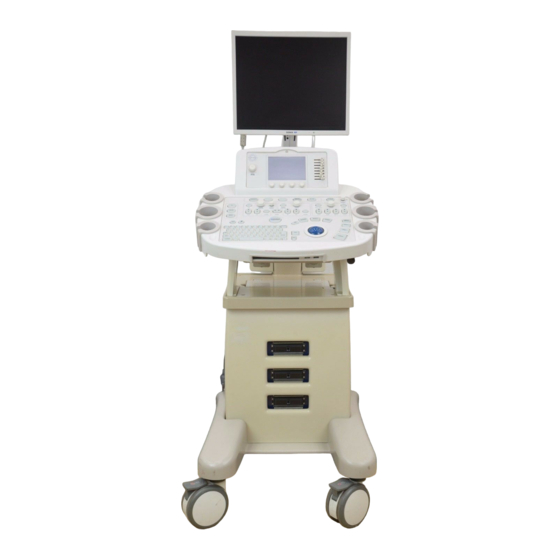
INTRODUCTION The SONIX Ultrasound System is a software driven, ergonomic, diagnostic medical device. The SONIX uses state of the art technologies to acquire, process, and display ultrasound data (see Figure 1-1). The system has four field serviceable components: LCD Display, Console, Ultrasound Modulo, and Transducers. -
Page 11: Physical Description
1.5.4 Transducers Ultrasonix offers a wide selection of high performance transducers for a variety of imaging applications. Incorporating the latest acoustic materials and technology, Ultrasonix’s lightweight transducers are ergonomic and durable for maximum clinical use. - Page 12 Chapter 1: General Information SSM – 001, Revision F SONIX Service Manual...
-
Page 13: Chapter 2: System Specifications
CHAPTER 2: SYSTEM SPECIFICATIONS DIMENSION Table 2-1: System Dimensions Measurement Metric Value US Value Width 53.34 cm 21.0 in Depth 60.96 cm 24.0 in Height 144.78 cm 57.0 in Weight 54.55 kg 120 lbs SYSTEM ARCHITECTURE • 256 channel fully digital broadband beamformer •... -
Page 14: Clinical Applications
CLINICAL APPLICATIONS • Abdominal • Vascular • Breast • Obstetrical • Cardiac • Prostate • Gynecological • Musculoskeletal TRANSDUCERS • 4DC6-3/40 broadband (3.5 MHz) 40mm 3D Abdominal • 4DC7-3/40 broadband (5 MHz) 40mm 3D Abdominal • C5-2/60 broadband (3.2 MHz) 60mm curved array •... -
Page 15: M Mode
2.6.2 M Mode • Sweep Speed • Sample Volume 2.6.3 Pulsed Wave Doppler • Doppler Gain • Doppler Frequency • Wall Filter • Sample Volume Angle • Pulse Repetition Frequency • Sweep Speed • Baseline 2.6.4 Color/Power Doppler • Color Gain •... -
Page 16: Image Storage
IMAGE STORAGE • DICOM level 3 • Still Image Storage (JPEG, DICOM, BMP, TIFF) • Cine Loop Storage (AVI) • Patient Management • CDR-W EXTERNAL CONNECTIONS • Parallel Port • Serial Port • USB Port (2 Ports) • Video IN/OUT •... -
Page 17: Electrical Ratings
2.12 ELECTRICAL RATINGS 100V—130V @ 50/60 Hz Input 200V—250V @ 50/60 Hz 115 VAC @ 4.0A (AC) Power Rating 240 VAC @ 2.0A (AC) Fuse Type 7A/250V SLO-BLO Fuse Size 6.4mm x 31.8mm 2.13 ADJUSTMENTS 2.13.1 Introduction This section will describe the various options available on the SONIX system in terms of the adjustments of voltage. - Page 18 Ecuador......110V Majorca......110/220V Egypt ......220V Malawi ......220V El Salvador....110V Malaysia ....... 220V Ethiopia ......220V Malta......220V Fiji .........220V Martinique..... 220V Finland ......220V Mexico ......110V France......220V Nepal ......220V French Guiana ....220V Netherlands ....220V Gambia ......220V Netherlands Antilles ..110/220V Germany .......220V New Caledonia .....
-
Page 19: Lcd Display Adjustment
Uganda......220V Zimbabwe ..... 220V Caution: Ensure the correct voltage rating has been selected before turning system ON. Contact an Ultrasonix Technical Support Representative if the appropriate voltage rating is not listed here (Table 2-2: World Electrical Voltage Rating, above). - Page 20 Chapter 2 – System Specifications SSM – 001, Revision F SONIX Service Manual...
-
Page 21: Chapter 3: System Installation
CHAPTER 3: SYSTEM INSTALLATION PRE-INSTALLATION PROCEDURE 3.1.1 Environmental Requirements Verify the system is to be operated in a room that meets the environmental requirements listed in Table 3-1 (below). Table 3-1: System Environment Specifications Item Metric Value US Value System Size: Width 53.34 cm 21.0 in System Size: Depth... -
Page 22: Instrument Input Power Rating
3.1.2.1 Instrument Input Power Rating An instrument input power rating has been established to clarify the maximum power requirement of the system with all accessories. Depending upon the accessories and options installed, the system may not draw the full amount of power listed below: Table 3-3: Instrument Input Power Rating Nominal System Power System... -
Page 23: Electromagnetic And Radio Frequency Interference
To avoid damaging the system, use ESD minimizing devices where needed. These ESD minimizing devices include: anti-static mats, humidifiers, and spray. Proper discharge is required before handling any electronic device such as an ESD strap. 3.1.4 Electromagnetic and Radio Frequency Interference This equipment has been tested and found to comply with the EMC limits for the Medical Device Directive 93/42/EEC (EN 55011 Class 1 and EN 60601-1-2). - Page 24 Table 3-6: EN 60601-1-2:2001 (Table 202) Guidance and Manufacturer’s Declaration—Electromagnetic Immunity SONIX Ultrasound Systems are intended for use in the electromagnetic environment specified below. The customer or the user of the SONIX Ultrasound System should ensure that it is used in such an environment.
- Page 25 Table 3-7: EN 60601-1-2:2001 (Table 204) Guidance and Manufacturer’s Declaration—Electromagnetic Immunity The SONIX is intended for use in the electromagnetic environment specified below. The customer or the user of the SONIX should ensure that it is used in such an environment. Immunity IEC 60601 Compliance...
- Page 26 Table 3-8: EN 60601-1-2:2001 (Table 206) Recommended Separation Distances Between Portable and Mobile RF Communications Equipment and the SONIX The SONIX is intended for use in an electromagnetic environment in which radiated RF disturbances are controlled. The customer or the user of the SONIX can help prevent electromagnetic interference by maintaining a minimum distance between portable and mobile RF communications equipment (transmitters) and the SONIX, as recommended below, according to the maximum output power of the communications equipment.
-
Page 27: Wiring Requirements
3.1.5 Wiring Requirements 3.1.5.1 Main AC Connection The electrical feed to the system should be a dedicated/isolated line (no other equipment on the same line) with a third-wire ground. Ensure a low impedance path for current to return to the source. 3.1.5.2 Network Connection It is the user’s responsibility to provide an Ethernet connection to the system and to install... -
Page 28: System Installation
1. Examine the shipping crate and box for any damage that may have occurred during transport. 2. Look for evidence to ensure that the crate has not been opened. 3. Report any damage to both the carrier and Ultrasonix. 3.2.3 Uncrating Instructions Note: Before uncrating the system, ensure there is adequate room for removing it from its packaging. -
Page 29: Mounting The Sx1.1 Arm For The Lcd Display
9. Cut one side of the cardboard attached to the wooden crate so the system can be rolled down. Note: It is best to cut the cardboard on the side facing the wheels. If there are at least two (2) people unpacking the system, it is possible to lift the SONIX out of the crate. - Page 30 2. Install the monitor’s arm onto the monitor’s tower. 3. Tighten the monitor arm's screw using the 4mm Allen Key provided with the system. Chapter 3: System Installation SSM – 001, Revision F SONIX Service Manual...
-
Page 31: Mounting The Lcd Display
3.2.5 Mounting the LCD Display Figure 3-1: LCD Display Assembly 1. Adjust the monitor base, rotating the support to face the back of LCD display. 2. Rest the LCD display on its support. 3. Fasten the base of the LCD display to the support arm with four (4) thumb screws (provided). -
Page 32: Connectivity Panel Check
3.2.6 Connectivity Panel Check The system case connectivity panel is accessible from the top of the system case. Check all cables are securely plugged into their respective slots. In addition, remove the rear cover as per section 12.2 and ensure the additional power cables are connected securely. Figure 3-2: Connectivity Panel (SX1.0) Figure 3-3: Connectivity Panel (SX1.1) Chapter 3: System Installation... - Page 33 A factory installed dongle is connected to this port which is required to activate some of the system features. This port Parallel port can be used to connect an Ultrasonix-approved parallel-port printer. Video output port This port is disabled.
- Page 34 Console power This port is used by the console. connector This port can be connected directly to an Ultrasonix approved switching device such as a foot pedal. 18 Freeze BNC The Foot Pedal action can be configured as explained in the Peripherals section.
-
Page 35: Back Connectivity Panel
The SONIX system provides two (2) USB ports and a DVD/CD writer at the front of the operator console. The two (2) USB Ports can be used to connect Ultrasonix-approved USB devices - such as a USB thumb drive - to the system for image file transfer. -
Page 36: Voltage Setup
3.2.9 Voltage Setup Before powering up the system, ensure that the voltage on the back of the machine corresponds with the voltage rating in your area as listed in section 2.13.2 Voltage Adjustment. If it is not, switch the voltage selector and the fuse box in the EMI Filter to the correct voltage rating. -
Page 37: Changing Fuses
Note: Make sure the fuse type is: 3AG Slo-Blo, 7A/250V 3.2.11 Final Inspection 1. Inspect the system for scratches or damage. Note any damage to the system and report it to Ultrasonix. 2. Plug main AC to primary power connector. 3. Turn on the LCD display. - Page 38 Chapter 3: System Installation SSM – 001, Revision F SONIX Service Manual...
-
Page 39: Chapter 4: Performance Test
CHAPTER 4: PERFORMANCE TEST INTRODUCTION This section describes the various tests performed on the system immediately following installation, upgrade and repair. The purpose of the performance testing is to verify correct operation of system (hardware, software and mechanical). During these tests, the system should be running in normal operation mode. -
Page 40: Image Test
Mode Default Applicable Command Default Programmables • • Annotation • Transducer Selection • Patient Management • Cine Loop • Freeze 1. Optimization Mode • Cine Loop Record 2. Sector Size/Zoom • All Modes Measurement 3. Optimization Mode DR • Mouse Wheel 4. -
Page 41: Communication Test
6. Select OK and exit the menu system. 7. To test, press the console QSONIX button and select Online Support. This should connect you to an Ultrasonix Technical Support Representative. Note: It may be necessary to restart in order for the changes to take affect. -
Page 42: Removable Hardware Test
When the software is started, a check for all hardware is performed. The areas tested are extremely crucial and if at any stage there is a failure, the system will not function properly. Please note the fault(s) when it occurs and report it to an Ultrasonix Technical Support Representative. -
Page 43: Chapter 5: Software Features
6. When the installation is complete, the software will reboot itself to apply the changes. CD Update 1. When an Internet connection is not available for any reason, contact an Ultrasonix Technical Support Representative and a CD version can be shipped. - Page 44 14. Press the console MENU button to check the software version. 15. Perform a scan and check the scanning modes to make sure the SONIX is working properly. Note: If an error occurs during installation, please contact an Ultrasonix Technical Support Representative for further instructions. Chapter 5: Software Features SSM –...
-
Page 45: System Recovery
• System ID Number (can be retrieved via MENU > Admin > Licensing • Windows Key (SONIX Recovery CD or SONIX Modulo or e-mail Ultrasonix for this license) • copy License.key from D:\ directory on to a USB memory stick •... - Page 46 Chapter 5: Software Features SSM – 001, Revision F SONIX Service Manual...
-
Page 47: Chapter 6: Connect Peripherals
CHAPTER 6: CONNECT PERIPHERALS B&W OR COLOR THERMAL PHOTO PRINTER Connect the BNC connector from "B&W (Video) Out" or "Col (Video) Out" (on the Back Connectivity Panel) to the "Video In" connection on the printer. Note: In the top panel, the video splitter’s green plug is for B&W and the blue plug is for Color. The system may have a T-connector attached to the green plug and blue plug allowing for a direct connection and a cleaner look. -
Page 48: Inkjet Or Laser Printer
INKJET OR LASER PRINTER 1. Open the Top Panel and plug the Inkjet or Laser printer USB cable into one of the USB ports. 2. To add a printer, press the console MENU button. Admin... > Peripherals 3. Click on Paper Printer Add Printer 4. -
Page 49: Chapter 7: Components And Assembly
Each component has a brief explanation of what it is and where such part could be found within the system. When service is preformed by Ultrasonix Technical Support, the label names on the components will be used to avoid any discrepancies. - Page 50 Chapter 7: Components and Assembly SSM – 001, Revision F SONIX Service Manual...
-
Page 51: Modulo Assembly
7.2.2 Modulo Assembly Figure 7-2: Modulo Assembly Drawings SONIX Service Manual SSM – 001, Revision F Chapter 7: Components and Assembly... - Page 52 Chapter 7: Components and Assembly SSM – 001, Revision F SONIX Service Manual...
- Page 53 SONIX Service Manual SSM – 001, Revision F Chapter 7: Components and Assembly...
-
Page 54: Cart Assembly
7.2.3 Cart Assembly Figure 7-3: Cart Assembly Drawings Chapter 7: Components and Assembly SSM – 001, Revision F SONIX Service Manual... - Page 55 SONIX Service Manual SSM – 001, Revision F Chapter 7: Components and Assembly...
- Page 56 Chapter 7: Components and Assembly SSM – 001, Revision F SONIX Service Manual...
- Page 57 SONIX Service Manual SSM – 001, Revision F Chapter 7: Components and Assembly...
- Page 58 Chapter 7: Components and Assembly SSM – 001, Revision F SONIX Service Manual...
-
Page 59: Electrical Components
ELECTRICAL COMPONENTS This section illustrates the various custom PCBs and main power components that are used. 7.3.1 Ultrasonix Custom PCBs Table 7-1: Ultrasonix Custom PCBs Component Name: ECHO US Module Board` Description: 12 Layers PCB. This board uses state of the art technology. -
Page 60: Power Management Components
7.3.2 Power Management Components Table 7-2: Power Management Components Component Name: Isolation Transformer Description: Medical Grade Isolation Transformer is used to stabilize the input voltage. Dimension: 6.5” Diameter Color: Component Name: Auto-Switching Power Supply Description: PC power supply that auto switches between 100V—130V and 200V—240V. - Page 61 Table 7-3: Cable Components SONIXSYSPWR: Tinned leads to Stereo 3.5mm Plug TOP ¼” TINNED SIGNAL ¼” 1" SIGNAL HEAT SHRINK 38" LABEL 3.5mm Stereo Plug SIGNAL 1 SIGNAL 2 SONIXTGC: MICROFIT 10 POS to MICROFIT 10 POS MICROFIT 10 POS PART# MOLEX# 43025-1000 1/2"...
- Page 62 SONIXTRACKSYS1: 6 POS CONNECTOR to 6 POS CONNECTOR HEAD ON VIEW OF MATING END 6 POS CONNECTOR PART# MOLEX 22-01-3067 1/2" Heat Shrink Molex 22-01-1064 connections: Connections ----------------------------------- PIN 5 of ZHR6 PIN 4 of ZHR6 PIN 5 of ZHR6 PIN 3 of ZHR6 PIN 5 of ZHR6 PIN 2 of ZHR6...
- Page 63 SONIX Service Manual SSM – 001, Revision F Chapter 7: Components and Assembly...
-
Page 64: Peripheral Components
The 1-position AC peripheral power cable is located in the Modulo utility panel area and can be accessed via the peripheral shelf door of the SONIX System. The connector is clearly labeled with “For use with Approved Ultrasonix Peripherals only” and is to be used for connecting third-party peripherals to the SONIX system. -
Page 65: Transducers
7.3.5 Transducers Table 7-4: Ultrasonix Transducers Component Name: 4DC 6-3/40 Transducer Description: 3.5 MHz array Component Name: 4DC7-3/40 Transducer Description: 5 MHz array Component Name: C5-2/60 Transducer Description: 3.2 MHz 60mm curved array. Component Name: C7-3/50 Transducer Description: 6 MHz 50mm curved array. - Page 66 Chapter 7: Components and Assembly SSM – 001, Revision F SONIX Service Manual...
-
Page 67: Chapter 8: Field Service Components
CHAPTER 8: FIELD SERVICE COMPONENTS INTRODUCTION This section describes how to service the four field serviceable components: LCD display, console, ultrasound modulo, and transducer. LCD DISPLAY SERVICING 8.2.1 Removing the Liquid Crystal Display (LCD) Display Tools required: None 1. Power off the SONIX system. 2. -
Page 68: Installing The Liquid Crystal Display (Lcd)
8.2.2 Installing the Liquid Crystal Display (LCD) Tools required: None 1. Install the LCD with 4 thumb screws. 2. Reconnect the three (3) cables: DVI/Power/USB. 3. Press the console MENU button. Admin... > Peripherals > Monitor > Factory Restore 4. Click on to perform a reset on the LCD display. - Page 69 4. Remove the back tower case by removing the two screws and pulling from the top and bending down the bottom. The back tower case is force fitted in. 5. Remove the front tower case by removing the two screws on each side. This case pulls off easily once the screws are removed.
-
Page 70: Replacing The Sx1.1 Lcd Display Cables
8.2.4 Replacing the SX1.1 LCD Display Cables Tools required: #1 Philips screwdriver #2 Philips screwdriver 2.5mm Allen key 10mm socket wrench 1. Power off the SONIX system and unplug it from the power outlet. 2. Remove the Rear Tower Shroud (20) using a 2.5mm Allen key to remove the four (4) Button Head Socket Screws (9). - Page 71 6. Use the #1 Philips screw driver and detach the two (2) screws (17) securing the Painted Upper Shroud and CM Neoflex Cableway (16). 7. In order to remove the Neoflex Arm from the CM Neoflex Upper Mount assembly (11), use the 10mm wrench to remove the four (4) Plate Screws (14) and four (4) M5 Split Lock washers (13).
- Page 72 8. Loosen the set screw (15) and remove the CM Neoflex Upper Mount Assembly and Pipe (11 and 12). Note: The set screw only needs to be loosened, not removed. 9. Use a #2 Philips screw driver and remove the two (2) Philips head screws (3). Lift off the CM Utility Panel Shield (2).
- Page 73 10. Use the 10mm wrench and remove the four (4) washers and plate screws (5 and 6) to detach subassembly (A) from the cart (B). 11. Use the 10mm wrench and remove the four (4) washers and plate screws (5 and 6) to detach the CM Neoflex Lower Mount (7) from the CM Neoflex Adapter (4).
-
Page 74: Console Servicing
CONSOLE SERVICING 8.3.1 Removing the Console Tools required: #2 Philips screw driver 10mm wrench 2.5mm Allen key 1. Power off the SONIX system and unplug it from the power outlet. 2. Remove the right plastic cover under the Console by unscrewing the four (4) Philips screws at the top and the two (2) Allen bolts on the right hand side. -
Page 75: Installing The Console
5. Use the 10mm wrench to remove the four (4) bolts from underneath the Console. 6. Carefully pull the Console up off the mounting plate, while feeding the cable up. 8.3.2 Installing the Console Tools required: #2 Philips screw driver 10mm wrench 2.5mm Allen key Non-permanent Glue Stick... -
Page 76: Ultrasound Modulo Servicing
ULTRASOUND MODULO SERVICING 8.4.1 Back-up User Data/Presets (as required) Before you replace the Ultrasound Modulo, you must back up user data such that it can be transferred into the new Ultrasound Modulo Equipment required: USB Memory stick or removable disk. 1. - Page 77 7. Select Transfer to access a list of available storage destinations. Storage Destination 8. Select the desired Image Format 9. Select the desired (.png, .jpeg, .bmp, .gif), 10. Select Send to transfer the files and/or images. The original files will remain unchanged in the Local memory.
-
Page 78: Removing The Ultrasound Modulo
8.4.3 Removing the Ultrasound Modulo Tools required: 4mm Allen key. 1. Power off the SONIX system. 2. Disconnect all transducers from the modulo. Note: This is an important step as transducer connectors attach to the modulo. 3. Unplug the system from the wall socket. 4. - Page 79 8. The modulo is held in place with four (4) more 4mm Allen screws located two (2) to a side (as below). 9. Remove these four (4) screws in order to remove the modulo from the cart. 10. Before sliding out the modulo, position the cardboard/plastic shield to protect the system's plastics from scratches.
-
Page 80: Installing The Ultrasound Modulo
8.4.4 Installing the Ultrasound Modulo Tools required: 4mm Allen key 1. Slide the new modulo into the rear opening with the transducer connectors facing front. Note: Remember to use a cardboard/plastic shield to protect the plastics. 2. Connect all the cables from the console and tower. Connect all cables from the console and tower. -
Page 81: Removing The Front Block
8. Press the console PROBE button and select the relevant transducer from the touch screen. 9. Ensure that the system is imaging properly (i.e., there are no oddities such as black lines, excessive noise, etc.). 10. Once the system is working, shut it down by pressing the console POWER button. 11. - Page 82 3. Remove the cables attached to the door. Note: Label the cables as each one is detached in order to avoid confusion during reinstallation. 4. To remove the door, undo the four (4) screws attached to the hinge. The two (2) screws on the top hinge are marked below.
-
Page 83: Replacing The Front Block
8.4.6 Replacing the Front Block Tools Required: #2 Philips screw driver 1. Attach the new Front Block via the hinge with the four (4) hinge screws. 2. Connect the cables as below. 3. The 3M cables coming from the PCI card are connected in reverse. The top plug of the PCI card (7) is connected to the bottom plug on the ultrasound modulo (8). -
Page 84: Replacing The Speaker Power Cable (Lcd Display Arm Sx1.0)
8.4.7 Replacing the Speaker Power Cable (LCD Display Arm SX1.0) 1. Remove the back panel of the SONIX as per section 8.4.3 Removing the Ultrasound Modulo, steps 5 - 7. 2. Remove the back tower case as per section 8.2.3 Replacing the SX1.0 LCD Display Cables, steps 5 - 7. -
Page 85: Transferring User Settings
8.4.9 Transferring User Settings Once the new ultrasound modulo has been installed, import the previously-saved user settings from the removable disk to this system. Equipment Required: USB Memory stick or removable disk containing previously exported User data. 1. Power on the SONIX system and wait till the system fully loads. 2. -
Page 86: Transducer Servicing
TRANSDUCER SERVICING 8.5.1 Introduction Ultrasound transducers are highly sensitive medical equipment requiring proper care and cleaning. There are two possible sources when a client is experiencing image problems: • transducer • ultrasound modulo’s transducer MUX board. 8.5.2 Testing the Transducer 1. -
Page 87: Transducer Maintenance
TRANSDUCER MAINTENANCE 8.6.1 Guidelines Ultrasonix recommends inspecting the SONIX transducers prior to each use: • Ensure the transducers are always clean before they are used. There must be no ultrasound gel (from previous imaging), any debris, films or unusual odors present. -
Page 88: Cleaning/Disinfecting Recommendations And Warnings For All Non-Invasive Transducers
DO NOT use sterilization or disinfections methods that have not been recommended by Ultrasonix. Severe damage will result. Please contact Ultrasonix if you have any doubt about sterilization or disinfection methods. Warning: Any transducer suspected of being contaminated with Creutzfeld Jacob disease material cannot be cleaned or sterilized. -
Page 89: Cleaning (Non-Invasive Transducers)
8.6.3.1 Cleaning (Non-Invasive Transducers) To clean the transducer: 1. After every patient exam, wipe the ultrasound transmission gel off the transducer. 2. Wipe the transducer and cable with a soft, dry or water-moistened cloth. 3. Wipe the transducer with either: •... -
Page 90: Maintenance (Non-Invasive Transducers)
Ultrasonix. DO NOT use sterilization or disinfection methods that have not been recommended by Ultrasonix. Severe damage will result. Please contact Ultrasonix if you have any doubt about sterilization or disinfection methods. Use of non-recommended cleaning agents may cause damage to the housing and will void transducer warranties. -
Page 91: Cleaning/Disinfecting Recommendations And Warnings For All Invasive Transducers
DO NOT use sterilization or disinfection methods that have not been recommended by Ultrasonix. Severe damage will result. Please contact Ultrasonix if you have any doubt about sterilization or disinfection methods. Warning: Any transducer suspected of being contaminated with Creutzfeld Jacob disease material cannot be cleaned or sterilized. -
Page 92: Cleaning (Invasive Transducers)
8.6.4.1 Cleaning (Invasive Transducers) Disinfect the transducer prior to the first exam and every exam thereafter. To clean the transducer: 1. Unplug the transducer. 2. Wash the transducer head and cable with soap and water to remove any protein buildup; however do not rinse or immerse the transducer near the strain relief. 3. -
Page 93: Maintenance (Invasive Transducers)
Ultrasonix. DO NOT use sterilization or disinfection methods that have not been recommended by Ultrasonix. Severe damage will result. Please contact Ultrasonix if you have any doubt about sterilization or disinfection methods. Use of non-recommended cleaning agents may cause damage to the housing and will void transducer warranties. -
Page 94: Storing And Packaging (Invasive Transducers)
Photocopy the form on page 87, complete it, and include it on the OUTSIDE of the shipping box or package Ultrasonix will not open the package until this form is checked by our Receiving Department. Chapter 8: Field Service Components SSM –... - Page 95 CUSTOMER NAME HOSPITAL/CLINIC NAME ADDRESS CITY/STATE COUNTRY/POSTAL CODE TELEPHONE E-MAIL SENDER'S FULL NAME SIGNATURE Mail the transducers to: Ultrasonix Medical Corp. c/o Courtney Hoffman Wetsco, Inc. 12505-A East 55 Street Tulsa, OK 74146 Tel: 1.918.459.3844 Fax: 1.918.459.3856 Web: www.ultrasonix.com E-mail: service@ultrasonix.com...
- Page 96 Chapter 8: Field Service Components SSM – 001, Revision F SONIX Service Manual...
-
Page 97: Chapter 9: Dicom Setup
CHAPTER 9: DICOM SETUP INTRODUCTION The system uses the Digital Imaging and Communications in Medicine (DICOM) standard to share medical information with other digital imaging systems. The SONIX, by means of the DICOM protocol, communicates with Storage, Storage Commitment, Print and Modality Worklist Service Class Providers. -
Page 98: Dicom Storage Configuration
9.2.1 DICOM Storage Configuration The DICOM Storage Settings pages offer basic and advanced settings for configuring the SONIX system for DICOM Image Storage. To configure the DICOM storage setting: 1. Select Settings next to the “Turn on DICOM Storage” checkbox on the DICOM configuration screen. - Page 99 The DICOM Storage Settings property page specifies how images are stored: Store Grayscale Images Select to store images as grayscale images. Select to swap the color components of the image pixel Convert BGR to RGB data—the blue colors are swapped with the red colors. Lossy Compression Quality Select the quality (1%–100%) of image compression.
- Page 100 The DICOM Storage Brightness/Contrast property page changes the brightness and contrast settings. These settings are applied to the images that are sent to the SCP not the images stored locally. The effects of these settings can be seen in the Before and After images.
- Page 101 The DICOM Storage Commitment property page enables configuration of the Storage Commitment AE. Check “Turn on Storage Commitment” to enable Storage Commitment feature. Local Host Properties of Storage Commitment SCU ( Service Class User) – SONIX system: SCU AE Title AE Title of the SONIX system.
-
Page 102: Dicom Print Configuration
9.2.2 DICOM Print Configuration The DICOM Print Settings pages offer basic and advanced settings for configuring the SONIX system for DICOM Print. To configure the DICOM print setting: 1. Select Settings next to the “Turn on DICOM Print” checkbox. 2. An onscreen menu with four (4) tabs to configure appears on the screen: •... - Page 103 The Print Settings property page enables configuration of general print properties: Select to print images in color, otherwise they are printed in Print in Color grayscale. Default is unchecked (print in grayscale) Reversed Brightness Select to print images in reversed brightness. Columns Select the number of columns per page.
- Page 104 The Advanced Print Settings property page enables configuration of advanced print properties: Orientation Select the orientation of the print page. Size Select the size of the print page. Magnification Select the method of magnification used. Select the smoothing. Printer specific – only available if Smoothing Cubic Magnification is selected.
- Page 105 The DICOM Print Brightness/Contrast property page changes the brightness and contrast settings: These settings are applied to the images that are sent to the SCP not to the images stored locally. The effect of these settings can be seen in the Before and After images Contrast Adjusts the level of contrast applied to the images.
-
Page 106: Dicom Worklist Configuration
9.2.3 DICOM Worklist Configuration The DICOM Worklist Settings pages offer advanced settings for configuring the DICOM Worklist SCU (Service Class User). To configure the DICOM Worklist settings: 1. Select Settings next to the “Turn on DICOM Worklist” checkbox. 2. An onscreen menu with two tabs appears on the display to configure: •... -
Page 107: Chapter 10: Network Connection
CHAPTER 10: NETWORK CONNECTION 10.1 INTRODUCTION The SONIX system can be configured to connect to the local network. In order for the network connection to function properly, please ask the IT department for assistance. 10.2 SETTING UP THE NETWORK CONNECTION 1. -
Page 108: Online Remote Support
10.3 ONLINE REMOTE SUPPORT Online remote support allows Ultrasonix Technical Support to view and control the SONIX for diagnostic purposes. 1. Press the console MENU button. Admin… Network > Online Remote Support 2. Click on .> 3. Enter the PIN provided by Ultrasonix Technical Support. -
Page 109: Chapter 11: License.key Importation
System Identification Number 4. Forward the to Ultrasonix to obtain a license.key file 5. When the license.key file arrives, copy it to a USB Memory stick. 6. Copy and paste the new license.key file onto the D: Drive. 7. Press the console MENU button to access User Settings Admin…... -
Page 110: Re-Import License.key From A Local Drive
Local Disk (D:) and locate license.key. Open 5. Click to re-import license.key. Note: If there are any problems, contact Ultrasonix Technical Support for assistance. Chapter 11: License Key Importation SSM – 001, Revision F SONIX Service Manual... -
Page 111: Chapter 12: Complete Plastics Replacement
CHAPTER 12: COMPLETE PLASTICS REPLACEMENT 12.1 INTRODUCTION This section describes how to disassemble the SONIX System mainly to replace the plastic covers. Tools required: 2.5mm Allen key 4mm Allen key #1 Philips screwdriver #2 Philips screwdriver 10mm wrench 12.2 REAR PLASTIC COVER REMOVAL To Remove the Rear Plastic Cover: 1. - Page 112 3. To slide the Ultrasound Modulo (3) out of the SONIX system (4), remove the two screws (5) located on each side of the SONIX system. A total of four screws. Please remember to detach all cables and transducers from the Ultrasound Modulo. Chapter 12: Complete Plastics Replacement SSM –...
-
Page 113: Console Support Plastics Removal
12.3 CONSOLE SUPPORT PLASTICS REMOVAL To remove the Console Support Plastics, follow the instructions in sections 12.3.1 and 12.3.2. 12.3.1 Inner Console Support and Console Assembly Plastics Removal 1. To remove the Left Inner Console Support Plastic (1) from the assembly, remove the four tap caps (2) off the screws located at the top. - Page 114 4. Remove the Cart Hinge Plastic (6) from the assembly by removing the four screws (7). 5. To detach the Console assembly (8), remove two screws at the rear of the tech board (9). 6. Detach the Front Handle (10) by removing the two screws (9). At this point, the Console assembly can be removed.
-
Page 115: Console Support Outer Plastic Removal
7. Remove the Console Support from the assembly. There are two types of Console Support: one for SP/RP model and one for OP model: a. To remove the Console Support SP/RP (11) from the assembly, remove the 4 screws (13). b. - Page 116 2. Remove the Cart Hinge Bracket (3) from the assembly by unscrewing the three screw/washer combinations (4). 3. Remove the Finishing Plug (6) from the Console Support Outer Plastic (5). Then remove the two screws (7) and the Console Support Outer Plastic can be detached. Chapter 12: Complete Plastics Replacement SSM –...
-
Page 117: Lcd Display Tower Plastics Removal
12.4 LCD DISPLAY TOWER PLASTICS REMOVAL 1. Remove the Rear Tower Plastic (1) by removing the two screws (2). Note: unclip the lower tooth on the Rear Tower Plastic. 2. Remove the Front Tower Plastic (3) by removing the two screws (4). Note: Unclip the lower tooth on the Front Tower Plastic. -
Page 118: Speaker Removal
12.5 SPEAKER REMOVAL 1. Remove the Panel Shield (1) by removing the two screws (2). 2. For each Speaker, unscrew the three screws (4) along with their lock washers (5). Remove the Speakers (3). Chapter 12: Complete Plastics Replacement SSM – 001, Revision F SONIX Service Manual... -
Page 119: Body Plastics Removal
12.6 BODY PLASTICS REMOVAL 1. Remove the four tap caps (1) off the four screws. 2. Remove the four screws (2) from the Peripheral Shelf Plastic. 3. Slide the Peripheral Shelf Plastic (3) over top of the LCD Display Tower Weldment (4). 4. - Page 120 6. On the Left and Right Structures, remove the three screws (10) on each side. 7. Carefully remove the Left and Right Side Plastics (11, 12). Note the lower tabs placement. 8. Carefully remove the Front Plastic (13). Note the lower tabs placement. 9.
- Page 121 10. Remove the two screws (17) and detach the Wheelbase Plastic (15). SONIX Service Manual SSM – 001, Revision F Chapter 12: Complete Plastics Replacement...
- Page 122 Chapter 12: Complete Plastics Replacement SSM – 001, Revision F SONIX Service Manual...
-
Page 123: Chapter 13: Maintenance
CHAPTER 13: MAINTENANCE 13.1 INTRODUCTION This section is intended to assist in effective cleaning and disinfections. It is also intended to protect the system and transducers against damage during cleaning or disinfections. Use the recommendations in this section when cleaning or disinfecting your ultrasound system, transducer, and accessories. -
Page 124: Recommended Frequency Of Maintenance Procedures
13.3 RECOMMENDED FREQUENCY OF MAINTENANCE PROCEDURES The frequency of preventive maintenance performed on the system plays a key role in extending or eliminating downtime due to poor performance or unexpected breakdown. Table 13-1 offers recommendations that must be weighed by factors like frequency of usage and environmental conditions. -
Page 125: Ergo Arm Tightening Sx1.0
13.4 ERGO ARM TIGHTENING SX1.0 Note: Refer to the System Label on the lower left side of the back of the SONIX. Ergo Arm tightening will apply only to systems with Serial Numbers beginning with SX1.0. From continued use, the Ergo arm of the LCD display may become loose. Tools required: Flat head screw driver ½... - Page 126 Chapter 13: Maintenance SSM – 001, Revision F SONIX Service Manual...
-
Page 127: Chapter 14: Troubleshooting
110 – 125V, China = 220 – 240V, etc. 3. Ensure the EMI Filter is in the ON state. 4. Finally, contact Ultrasonix for further instructions to power up system. To check the fuse: 1. Ensure the system is completely turned off. -
Page 128: Check The Dicom Settings
Power up the SONIX. Plug the USB connections. The CD/DVD drive should now be recognized. Restart the SONIX. Contact an Ultrasonix Technical Support Representative if you are still having trouble with your CD/DVD drive. Chapter 14: Troubleshooting SSM – 001, Revision F... -
Page 129: Regedit
ENTER. HKEY_CURRENT_USER > Software > Ultrasonix > Exam > 4. In the registry, go to Settings Note: Make the necessary settings changes here when advised by an Ultrasonix Technical Support Representative. SONIX Service Manual SSM – 001, Revision F... -
Page 130: Hardware Test Software
Note: Hold down the ALT button and press TAB as many times as necessary to move to the desired program. Windows Explorer 10. In , go to C:\Program files\Ultrasonix\Exam and double-click Hwtest.exe. Initialize 11. Click and wait for the results. - Page 131 30 (it ranges from 0 to 127). Apply Changes 21. Click on 22. Record and save the findings in Notepad , then send the file to an Ultrasonix Technical Support Representative. SONIX Service Manual SSM – 001, Revision F Chapter 14: Troubleshooting...
-
Page 132: Lcd Display Is Blank, Touch Screen Displays Correctly
1. Press SHIFT + Fn + J simultaneously on the keyboard to reset the display setting to the factory defaults. Option 2: To obtain help from an Ultrasonix Technical Support Representative: By following the steps listed below, a temporary video connection can be made to enable an Ultrasonix Technical Support Representative to help restore the display settings. -
Page 133: Lcd Display Works, But Touch Screen Still Displays Ultrasonix Logo Even In Imaging Mode
14.9 LCD DISPLAY WORKS, BUT TOUCH SCREEN STILL DISPLAYS ULTRASONIX LOGO EVEN IN IMAGING MODE Option 1: To ensure the Serial Cables are properly connected: 1. Shut down the SONIX. 2. Unplug, then re-plug both serial cables (refer to Figure 3-2: Connectivity Panel (SX1.0), Figure 3-3: Connectivity Panel (SX1.1) and Table 3-9: Connectivity Panel... -
Page 134: Sonix Does Not Boot, Error Is Displayed On The Screen
System Recovery will need to be performed. Please locate the System Recovery CD which came with the SONIX and contact Ultrasonix Technical Support for further instructions. Caution: Do not attempt a System Recovery without first consulting an Ultrasonix Technical Support Representative. - Page 135 Notes SONIX Service Manual SSM – 001, Revision F Notes...
- Page 136 Notes SSM – 001, Revision F SONIX Service Manual...
Need help?
Do you have a question about the SONIX Series and is the answer not in the manual?
Questions and answers