Table of Contents
Advertisement
Quick Links
Advertisement
Table of Contents

Related Manuals for Ultrasonix SonixTouch Q+


Summary of Contents for Ultrasonix SonixTouch Q+
- Page 1 Service Manual Analogic Ultrasound SonixTouch Q+ Ultrasound System...
- Page 3 Ultrasonix Medical Corporation SonixTouch Q+ Ultrasound System Service Manual Ultrasonix Medical Corporation 130 – 4311 Viking Way Richmond, BC V6V 2K9 Canada www.analogicultrasound.com support@ultrasonix.com 1.866.437.9508 1.604.279.8550 1.778.296.3860 (Support) © 2014 Analogic Corporation 00.053.204, Revision A, June 27, 2014 All Rights Reserved.
-
Page 5: Table Of Contents
TABLE OF CONTENTS CHAPTER 1: GENERAL INFORMATION..............................1-1 AUDIENCE ........................................1-1 1.1.1 Prescription Device ....................................1-1 VOLTAGE DISCLAIMER ....................................1-1 CONNECTIVITY DISCLAIMER ..................................1-1 PATIENT PRIVACY....................................... 1-1 SERVICE DISCLAIMER ....................................1-1 LICENSE AGREEMENT....................................1-2 TRADEMARKS AND PATENTS..................................1-2 SYSTEM OVERVIEW....................................1-3 PHYSICAL DESCRIPTION ................................... - Page 6 Software Update via a Downloaded File..............................5-2 SHOW/HIDE PROTOCOLS (VIA SERVICE MODE) .............................5-3 PATIENT DATABASE REPAIR ..................................5-4 SYSTEM RECOVERY....................................5-4 CHAPTER 6: PERIPHERALS AND ACCESSORIES ............................ 6-1 PERIPHERAL COMPONENTS ..................................6-1 ULTRASONIX-APPROVED DEVICES ................................6-1 PRINTER SETUP......................................6-1 6.3.1 Local Printer Setup ....................................6-1 6.3.2 Network Printer Setup....................................6-2 6.3.3...
- Page 7 RETURNING PARTS FOR SERVICE/REPAIR/REPLACEMENT....................... 7-40 7.9.1 Transducers ......................................7-40 7.9.2 UPS Battery ......................................7-40 CHAPTER 8: DICOM...................................... 8-1 DICOM CONFIGURATION OPTIONS ................................8-2 8.1.1 Global Settings......................................8-2 8.1.2 DICOM Storage Settings..................................8-2 8.1.2.1 DICOM Storage Settings – AE Configuration ............................ 8-3 8.1.2.2 DICOM Storage Settings –...
- Page 8 11.3 TRANSDUCER MAINTENANCE.................................. 11-8 11.3.1 Usage Guidelines ....................................11-8 11.3.2 Ultrasound Coupling Gels..................................11-8 11.3.3 General Transducer Maintenance ................................ 11-9 11.3.3.1 Inspection and Testing ..................................11-9 11.3.3.2 Storing and Packaging ..................................11-9 11.3.4 General Transducer Cleaning/Disinfecting Recommendations and Warnings ................... 11-10 11.3.5 Cleaning/Disinfecting Non-Invasive Transducers ..........................
-
Page 9: Chapter 1: General Information
Personal Information Protection and Electronic Documents Act (PIPEDA–Canada)). In order to ensure regulatory compliance, Ultrasonix will not remove the system hard drive – and the patient data it contains – from the customer site. In the event the hard drive must be removed from the system, it will be returned to the customer. Final disposition of the hard drive and its data will remain the customer's responsibility. -
Page 10: License Agreement
Ultrasonix, or its suppliers, retain(s) ownership of and title to any computer program supplied with the Equipment and to the trade secrets embodied in such computer programs. Subject to the Buyer’s acceptance and fulfillment of the obligations in... -
Page 11: System Overview
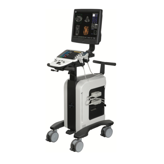
SYSTEM OVERVIEW The SonixTouch Q+ Ultrasound System is a software driven, ergonomic, diagnostic medical device. It uses state of the art technologies to acquire, process and display ultrasound data (Figure 1-1). The system has several major field serviceable components including: LCD display with built-in speakers and a multi- position, articulated lift system, operator console, modulo, transducers and UPS. -
Page 12: Physical Description
– are encased in an aircraft grade aluminum composite case for ease of service. 1.9.4 Transducers Ultrasonix offers a wide selection of high performance transducers for a variety of imaging applications. Incorporating the latest acoustic materials and technology, these lightweight transducers are ergonomic and durable for maximum clinical use. Refer to 6.7.1 Transducer Disclaimer... -
Page 13: Chapter 2: System Specifications
CHAPTER 2: SYSTEM SPECIFICATIONS DIMENSIONS Table 2-1: System Dimensions Measurement Metric Value US Value Width 53.5 cm 21 in Depth 91.5 cm 36 in Height, highest position (measured from top of LCD display to floor) 155 cm 61 in Height, lowest position (measured from top of LCD display to floor) 139.7 cm 55 in Weight (with UPS and battery) - Page 14 Chapter 2: System Specifications 00.053.204, Revision A SonixTouch Q+ Service Manual...
-
Page 15: Chapter 3: System Installation
Warning: Operate in an indoor environment only, free from moisture, flammable liquids, gases, corrosive substances, strong electrical or magnetic fields and equipment that generates high frequency waves. Ultrasonix cannot guarantee the proper performance of the system if used in the above-listed conditions. Table 3-2: Barcode Reader Operating Temperature 32º... -
Page 16: Electrical Requirements
3.1.2 Electrical Requirements Verify the system is to be operated in a room that meets the electrical requirements listed below. Table 3-4: Electrical Specifications Electrical Rating Value 100V—120V @ 50/60 Hz Measurement (System Only) 200V—240V @ 50/60 Hz 120 VAC @ 7.0A Current Draw (System Only) 240 VAC @ 4.0A Power Draw (System Only @ peak) -
Page 17: Electrostatic Discharge
3.1.3 Electrostatic Discharge During normal operation, the presence of electrostatic discharge (ESD) can cause system reliability issues. The following are the most common causes for ESD: • moving people • low humidity • improper grounding • unshielded cable • poor connection •... -
Page 18: Wiring Requirements
Caution: System networking options are intended for use inside your organization's firewall. Organizations that elect to configure/use the networking functionality provided by Ultrasonix are assuming all liabilities and risks associated with that decision. 3.1.5.3 Image Management Network Obtain the following information from the system administrator: •... -
Page 19: Pre-Installation
Examine the "Tip’n Tell" attachment on the outside of the package to ensure the crate has not been tipped too far during transport and delivery (refer to Figure 3-1 for details). Report any damage to both the carrier and Ultrasonix. 3.2.2 Unpacking Instructions Equipment/Tools/Personnel Required: •... -
Page 20: Unpacking A System
3.2.2.1 Unpacking a System To Unpack a System: Cut and remove the four ¼” nylon strap around the box. Caution: Stand out of the way when cutting these straps as they are under tension and may snap back when severed. Lifting from the bottom, remove the cardboard cover. - Page 21 Cut off and remove the strapping before removing the printer from the rear of the system. Note: The strapping is only applied if a printer is included with the system. At the rear of the system, pull off the padding protecting the neck of the LCD display stand. Note: Do not use a blade or scissors to cut the padding as this may result in damage to the system.
- Page 22 Remove the foam packing from the sides of the system. Remove any transducers and biopsy kits packed around the system. Remove the foam packing from around the front wheelbase. Undo the back cardboard flap and remove the foam from the rear of the system. Chapter 3: System Installation 00.053.204, Revision A SonixTouch Q+ Service Manual...
- Page 23 Remove the foam ramps from either side of the system. Remove the foam divots. Note: The system can be unloaded either from the front or back of the packing crate. Open out the base and use the rear handles to tip the system back, lifting the front wheels clear the foam depressions.
- Page 24 Unlock all casters (1: total lock, 2: completely unlocked). Depending on whether the system is being unloaded from the front or back of the packing crate, use the rear handles to push or pull the system down the ramps and off the palette. Caution: Because the wheels sit in depressions, the system will have to be semi-lifted out of these in order to roll it down the ramp.
-
Page 25: Installation
INSTALLATION 3.3.1 Mechanical Inspection 3.3.1.1 Wheels The system is equipped with dual lock castors that can be set in three distinct positions. Figure 3-2: Dual Lock Brakes Table 3-1: Dual Lock Brakes Total lock: casters cannot move (both levers in lowest position). Directional lock: casters are directionally locked, restricting them to front/back movement only (dark gray lever in lowest position, light gray lever in highest position). -
Page 26: Console Height, Angle And Swivel Adjustment
3.3.1.3 Console Height, Angle and Swivel Adjustment Ensure the console's three adjustments work smoothly: height, angle and swivel. To Adjust the Console Height: Depress the system foot pedal (1). Note: Keep the foot pedal depressed until the height adjustment is complete. Pull up or push down on the front pull handles (2) to raise or lower the console. -
Page 27: Emi Filter And Power Panel
3.3.2 EMI Filter and Power Panel The system is delivered with a voltage rating label over the power switch and EMI filter. The precise wording on the label is determined by the voltage setting on the EMI filter. Double check that the voltage rating on the label matches the voltage configuration on the EMI filter, then remove the label. - Page 28 Equipment/Tools Required: • fine tipped, narrow shafted, flat head screwdriver (e.g., ⅛ " (3mm) jeweler's screwdriver). Warning: Do not perform any internal system maintenance if the UPS breakers are turned on. To Change Voltage Settings: Power off and unplug the power cord from both the wall outlet and the system. Use the screwdriver to open the fuse box lid.
-
Page 29: Powering The System
3.3.3 Powering the System Before turning on the system, connect the power cord. To Connect the Power Cord: Remove the bubble wrap protecting the AC (system) power cord and unwrap the cord from its holder. Ensure the power cord is firmly connected to the AC power cord receptacle (Figure 3-5). -
Page 30: Changing Fuses
3.3.3.2 Changing Fuses Equipment/Tools Required: • two 3AG Slo-Blo, 7A/250V fuses • fine tipped, narrow shafted, flat head screwdriver (e.g, ⅛" (3mm) jewelers screwdriver). Warning: Do not perform any internal system maintenance if the UPS breakers are turned on. To Change the Fuses: Power off and unplug the power cord from both the wall outlet and the system. -
Page 31: Ups Configuration (If Applicable)
Should the UPS require maintenance or replacement, only qualified Ultrasonix Service Technicians may perform service as detailed in the Service Manual. - Page 32 Caution: It is important to turn on the breakers in the order specified. Note: Although they are marked "EMERGENCY SHUTDOWN ONLY", these openings are also intended to give breaker access to qualified Ultrasonix Service personnel. Turn 2: AC Input Breaker to the ON position.
-
Page 33: Transducer Inspection
System Initialization To Initialize the System: Inspect the system for scratches or damage. Note any damage to the system and report it to Ultrasonix. Connect at least one transducer to the system. Note: Most transducers can be inserted in any of the transducer cone ne ct ion ports. However, to ensure proper function insert: •... -
Page 34: Peripherals (If Applicable)
Figure 3-7: Peripheral Receptacle Location 3.3.7.1 USB Printer Mounting Kit (If Applicable) If the USB printer was purchased from Ultrasonix, it can be mounted on the system without the peripheral tray using a specially designed printer mounting kit. Note: When ordered with a new system, the mounting plate will be attached to the printer at the factory. When a new system will be used with an existing printer, the mounting plate will have to be attached in the field. -
Page 35: Printer Installation (Without Peripheral Tray)
3.3.7.2 Printer Installation (without Peripheral Tray) If the USB printer was purchased from Ultrasonix, it can be mounted on the system without the peripheral tray using a specially designed printer mounting kit. Note: Refer to 6.3.1 Local Printer Setup for details on configuring the USB printer. -
Page 36: Peripheral Tray And Basket
3.3.7.3 Peripheral Tray and Basket If the system order included the peripheral tray it will come pre-installed—with the exception of the peripheral tray basket. The basket must be installed after delivery. Note: The peripheral tray is not available for systems with SonixGPS installed. To Attach the Peripheral Tray Basket to the Peripheral Tray Using the two sets of supplied nylon washers and thumbscrews, attach the peripheral tray basket to the peripheral tray while the tray is attached to the system. -
Page 37: Barcode Reader
To Attach the Peripheral Tray Basket to the Peripheral Tray From underneath the back of the peripheral tray, fasten the two thumbscrews (1) through the holes provided into the two "threaded standoffs" (2) (already attached to the base of the USB printer. Note: Refer to Figure 3-8 Table 3-4... -
Page 38: Set System Date And Install Licenses
SET SYSTEM DATE AND INSTALL LICENSES Follow the instructions on the Setup/License card included with the system. Note: The instructions on the Setup/License card must be completed in the proper order: • A: Setting System Date/Time Parameters • B: Enabling System Licenses. Chapter 3: System Installation 00.053.204, Revision A SonixTouch Q+ Service Manual... -
Page 39: Chapter 4: Performance Testing
CHAPTER 4: PERFORMANCE TESTING This section describes the various tests performed on the system immediately following installation, updating and repair. The purpose of performance testing is to verify the correct operation of both hardware and software as well as mechanical items. During these tests, the system should be running in normal operating mode. -
Page 40: Image Test
IMAGE TEST To Conduct an Image Test: Connect each of the different transducers available and tap the touch screen B button. Note: Most transducers can be inserted in any of the transducer connection ports. However, to ensure proper function insert: •... -
Page 41: Pulsed Doppler Sound Test
PULSED DOPPLER SOUND TEST To Conduct a Pulsed Doppler Sound Test: Ensure the system is powered on and has completed the initialization sequence. Ensure the system has an exam screen showing. Tap the touch screen PW button. Press the console button. - Page 42 Chapter 4: Performance Testing 00.053.204, Revision A SonixTouch Q+ Service Manual...
-
Page 43: Chapter 5: Software
The system will default to the Update Location "Internet Update". Select Update. The system will automatically download, auto-install, and restart the software. Note: If an error occurs during installation, contact Ultrasonix Technical Support for further instructions. SonixTouch Q+ Service Manual 00.053.204, Revision A... -
Page 44: Software Update Via A Downloaded File
If the system is not connected to the Internet, but a computer with Internet access is available, download the update from the Ultrasonix website, ensuring that it’s copied to the root of a USB device (memory stick, external hard drive, etc.). -
Page 45: Show/Hide Protocols (Via Service Mode)
SHOW/HIDE PROTOCOLS (VIA SERVICE MODE) Follow the directions below to hide any Protocols the customer may not wish to see (have accessible). Note: Users can also configure the available Protocols for themselves from Menu > Administrator > Preset > Protocols…. To Show/Hide Protocols: Tap the touch screen Menu button. -
Page 46: Patient Database Repair
Select OK to exit. SYSTEM RECOVERY Before performing a system recovery, consult Ultrasonix Technical Support as this should only be done as a last resort. Technical Support will provide the appropriate documentation to carry out a system recovery. Caution: System Recovery may erase all data on the hard drive, including Patient/Exam data! Chapter 5: Software 00.053.204, Revision A... -
Page 47: Chapter 6: Peripherals And Accessories
The 1-position AC peripheral receptacle is located on the back of the system (to the left of the EMI filter). The connector is clearly labeled “Only Ultrasonix-approved peripheral devices may be connected to this power receptacle” and is to be used to connect only Ultrasonix-approved, third-party peripherals to the system. -
Page 48: Network Printer Setup
6.3.2 Network Printer Setup This section uses the HP DeskJet 5440 as the example Network Printer and is meant only as a guide as not all networks are identical. These instructions can also be used as a reference for installing other system network printers. To Connect the Network Printer to the System: Note: Before proceeding, ensure that the network has a shared printer. -
Page 49: Configuring Custom Keys
Select Yes to set the selected printer as the default. Select Next to print a test page. Select Finish to complete the installation. 6.3.3 Configuring Custom Keys 6.3.3.1 Paper Printing Configuration To Configure a Print Key for Paper Printing: Tap the touch screen Menu button. Select Administrator >... -
Page 50: Image Sheet Printing
6.3.3.3 Image Sheet Printing To Configure Image Sheet Printing: Tap the touch screen Menu button. Select Administrator > Peripherals. Select the Paper Printer tab. To select/deselect Image Sheet Printing (e.g., 2x3 image sheets), check/uncheck the Enable box. Enter the number of Columns and Rows desired in the text boxes provided. Note: The default is set to print as two columns by three rows (for a total of six images per sheet). -
Page 51: Connecting The Usb Footswitch (Dual Or Triple)
None, Print, Freeze, Quick Cine Record, Exam Management, Measurement, Exam Review, SonixDVR, Next Transducer and Transducer 1, 2, or 3. Figure 6-3: Peripherals – Footswitch Table 6-3: Footswitch Options Ensure an Ultrasonix-approved Footswitch has been connected, then select checkbox to Enable BNC Footswitches enable Footswitch operation. None... -
Page 52: Barcode Reader
• via the TV’s PC IN connector, providing this connection is either DVI or HDMI. Caution: When connecting an external TV, be sure to follow all instructions carefully. Note: While a selection of televisions were tested against the following instructions, Ultrasonix cannot guarantee that all TVs will function as an external monitor. -
Page 53: Method 1: Via The Tv's Hdmi Or Dvi Input
6.6.1 Method 1: Via the TV’s HDMI or DVI Input Search the TV manufacturer's user guide to determine whether or not the TV’s HDMI or DVI Input will accept the required signal format. Table 6-4: Required Signal Format Format Resolution V. -
Page 54: Method 2: Via The Tv's Pc In Connector
6.6.2 Method 2: Via the TV’s PC IN Connector Search the TV manufacturer's user guide to determine whether or not the TV’s PC IN connector will accept the required signal format. Table 6-5: Required Signal Format Format Resolution V. Frequency 1024 x 768 60 Hz Determine the type of connector required by the TV’s PC IN connector in order to source the correct cable:... -
Page 55: Accessories
ACCESSORIES 6.7.1 Transducer Disclaimer Certain transducers may not be available in all markets. Consult your local Ultrasonix Authorized Distributor or Sales Representative to determine availability in your area. 6.7.2 Transducer Models The transducers in Table 6-6 may include models that are no longer offered for sale. - Page 56 m4DC7-3/40 (Mini Motor-driven Curved Array) 4DEC9-5/10 (Motor-driven Endocavity Microconvex Array) EC9-5/10 and EC9-5/10 GPS (Endocavity Microconvex Array) Chapter 6: Peripherals and Accessories 00.053.204, Revision A SonixTouch Q+ Service Manual 6-10...
-
Page 57: Chapter 7: Field Service Components
This will ensure access to this data if either the modulo or hard drive needs replaced during servicing. The following options are available for export: Note: When creating a backup prior to servicing or replacing the modulo, Ultrasonix recommends selecting all options for Export. - Page 58 Select Administrator > System > Export…. Check the item(s) to be exported. Note: When creating a backup prior to servicing or replacing the modulo, Ultrasonix recommends selecting all options for Export. Ensure the backup media (Device Status) has been properly detected. If the External Storage Detected is (Q:|), the backup process will fail.
-
Page 59: Importing User Data (As Required)
7.1.2 Importing User Data (As Required) Once the modulo has been installed, if required, import (restore) the previously-saved User Data from the removable disk to this system. Note: If the system boots properly with all User Data intact, then it will not be necessary to import this data. The following options are available for import: •... - Page 60 To Import User Data from a Backup: Caution: Ultrasonix does not recommend importing user-defined Presets created with a previous software version as they may not be compatible for use with a more recent software update. Ensure the system is plugged in and powered on.
-
Page 61: Exporting Patient/Exam Data (As Required)
7.1.3 Exporting Patient/Exam Data (As Required) Exam Import/Export enables data to be copied to and from the system from within the system software, allowing the creation of Patient/Exam data backups. Note: When creating a backup prior to servicing the modulo, be sure to select all Patient/Exam data currently stored on the system. -
Page 62: Importing Patient/Exam Data (As Required)
7.1.4 Importing Patient/Exam Data (As Required) Exam Import/Export enables data to be copied to and from the system, allowing the reinstallation of Patient/ Exam data backups. Note: When reinstalling Patient/Exam data after servicing the modulo, be sure to select all Patient/Exam data for import to the system. -
Page 63: Backing Up/Exporting Patient Data Via The Service Mode Option
7.1.5 Backing up/Exporting Patient Data via the Service Mode Option This function allows Service Technicians to backup (and restore) Patient/Exam data. It does not, however, backup any of the User Data settings (7.1.1). Note: If Patient/Exam data is backed up using these instructions (7.1.5), it will not be necessary to use the Export option (7.1.3). - Page 64 Select Go. Note: The system will auto-detect the USB storage device. Select Backup. If the USB device already contains patient data, the following message will be displayed. Select OK to continue or Cancel to exit without creating a backup. Once the procedure is complete, the following message will be presented. Select OK to continue. Chapter 7: Field Service Components 00.053.204, Revision A SonixTouch Q+ Service Manual...
-
Page 65: Restoring/Importing Patient Data Via The Service Mode Option
7.1.6 Restoring/Importing Patient Data via the Service Mode Option In order to restore Patient/Exam data via Service Mode, it must first have been backed up using this option. Refer 7.1.5 for backup details. During the restoration process, the system will warn – in a multi-step process – about overwriting any patient data that already exists on the system hard drive. - Page 66 When the following warning message appears, select Yes to continue or No to exit without restoring Patient/ Exam data. When a PatientInfo folder already exists on the system, the following warning will be presented. Select Yes to continue or No to exit without restoring Patient/Exam data. When Patient/Exam data already exists on the system, a final warning will be presented.
-
Page 67: Turning The Ups Breakers On And Off
TURNING THE UPS BREAKERS ON AND OFF 7.2.1 Determining Whether the UPS Breakers are ON or OFF To determine whether the breakers are ON or OFF without removing the side shroud, check to see if there is a visible white marking at the top of each breaker. If there is, the breaker is OFF. Note: Breaker access is at the bottom of side shroud B (Figure 6-1). -
Page 68: Turning On The Ups Breakers
7.2.3 Turning ON the UPS Breakers Warning: Do not perform any internal system maintenance if the UPS breakers are turned on. Note: Breaker access is at the bottom of left side shroud (Figure 6-1). To Turn ON the UPS Breakers: Plug in the system. -
Page 69: Accessing The Modulo
7.2.4 Accessing the Modulo Depending on the tasks to be performed, it may only be necessary to remove one side shroud. Note: Because the modulo is accessible from the side of the system, not all service tasks necessitate its removal. Figure 7-2: Accessing the Modulo (Exploded View) Left Side Shroud Left f f Side Shroud... - Page 70 Equipment/Tools Required: • 4mm Allen key Note: A 4mm Allen key is shipped with the system. To Remove the Right Side Shroud: Power off and unplug the system. Disconnect all transducers from the modulo. Using a 4mm Allen key, give each of the two shroud fasteners a quarter turn to the left. Close-up of loosened shroud fastener Note: The fasteners will loosen, but remain attached to the shroud.
- Page 71 To Remove the Left Side Shroud: Power off and unplug the system. Disconnect all transducers from the modulo. Using a 4mm Allen key, give each of the two shroud fasteners a quarter turn to the left. Close-up of loosened shroud fastener Note: The fasteners will loosen, but remain attached to the shroud.
-
Page 72: Replacing The Side Shrouds
7.2.6 Replacing the Side Shrouds To Reinstall the Right Side Shroud: Insert the tabs on the bottom of the shroud into the slots in the frame. Ensure the bottom sides of the shroud are clear of all cables and are sitting in the correct position. Note: This may take a little bit of maneuvering. -
Page 73: Replacing The Modulo
Undo all modulo cables/connections on the System Case Connectivity Panel, cutting cable ties only as needed. Note: Due to the number of connections involved in this and the next few steps, Ultrasonix recommends marking the location of all unlabeled wires/cables by labeling them with masking tape. - Page 74 Disconnect the three (bottom left rear) power cables connected to the modulo: LCD display power cable (1), UPS input power cable (2) and UPS output power cable (3). System Power Connection EMI Filter Note: The LCD display power cable (1) is color coded with green tape.
-
Page 75: Installing The Modulo
7.3.2 Installing the Modulo Equipment/Tools Required: • 4mm Allen key • 10mm wrench • 7mm wrench • #2 Phillips screwdriver • cable ties. Warning: Do not perform any internal system maintenance if the UPS breakers are turned on. Caution: Always wear a grounding strap when opening and working inside the modulo. To Install the Modulo: Slide the modulo into the side opening with the transducer connectors facing right. -
Page 76: Connectivity
Using the 10mm wrench, fasten the washer and nut securing the ground mesh from the modulo to the console. Using the 7mm wrench, fasten the washer and nut securing the ground wire from the modulo to the LCD display and, if applicable, to the ECG (refer to image step Ensure all cables are properly connected to the System Case Connectivity Panel. - Page 77 Not in use. (May or may not be present.) System Speaker connection (green). 10 Sound Connections Line-in (blue): may be used to connect an Ultrasonix-approved audio input device. System Microphone connection: Disabled. (May or may not be present.) RS232 Serial Port(s) Used by the UPS.
- Page 78 Not in use. (May or may not be present.) Power Hub Power Connector with 3-Way Adapter Used by the Speakers (1), ECG (2) and LED-lit Ultrasonix logo (3). with 4-Way Adapter Power Switch Used by the system ON/OFF switch as well as for UPS power.
-
Page 79: Back Connectivity Panel
For details on connecting an external TV, refer to 6.6. 7.3.3.3 Console Connectivity The system provides two USB ports at the side of the operator console. They can be used to connect Ultrasonix- approved USB devices (such as a USB thumb drive for image file transfer). -
Page 80: Testing The Modulo And Ups
7.3.4 Testing the Modulo and UPS After the modulo or UPS have been removed and reinstalled – for whatever purpose – test the UPS and modulo to ensure all cables have been properly connected. Note: If the system was ordered without a UPS, follow the test instructions in 7.3.5 To Test the UPS and Modulo: Turn 1: Battery Breaker to the ON position. -
Page 81: Testing The Modulo (No Ups Installed)
7.3.5 Testing the Modulo (No UPS Installed) After the modulo has been removed and reinstalled – for whatever purpose – test it to ensure all cables have been properly connected. Note: If the system was ordered with a UPS, follow the test instructions in 7.3.4. To Test the UPS and Modulo: Plug in the power cord. -
Page 82: Front Block/Ultrasound Module Servicing
FRONT BLOCK/ULTRASOUND MODULE SERVICING Modulo Servicing has been divided into two separate sections, the first (7.3 Replacing the Modulo) dealt with the modulo as a discreet entity. This, the second section, deals with front block/ultrasound module servicing. Caution: Before doing any work with the modulo, be sure to complete sections 7.1.1 7.1.3 (or 7.1.5) in order to the... - Page 83 To Open the Front Block/Ultrasound Module: Note: In order to access the screws holding the Front Block/Ultrasound Module closed, the modulo must be "detached" from the cart and slid forward about an inch or so. While three power cables will have to be unplugged, the System Case Connectivity Panel (7.3.3.1) can be left untouched.
- Page 84 From the back, gently push the modulo forward until the "Service Access" screws are revealed. Caution: When pushing the modulo forward, take care to ensure that the cabling is protected from nicks and cuts. Using the #2 Phillips screwdriver, unfasten the two screws securing the Front Block. Note: The screws will be labeled with a Service Access sticker.
-
Page 85: Removing The Front Block/Ultrasound Module
7.4.3 Removing the Front Block/Ultrasound Module To remove the front block/ultrasound module without removing the modulo, follow the instructions in 7.4.1 7.4.2 before continuing to the instructions below. To remove the front block/ultrasound module after removing the modulo, follow the instructions in 7.3.1 7.4.2 before continuing to the instructions below. - Page 86 Open the door wider to expose the Side EMI Strip. Using the #2 Phillips screwdriver, from the exterior of the modulo, remove the two screws fastening the Side EMI Strip over the door hinges. Remove the modulo door hinge cover from inside the modulo and expose the two hinges. To remove the door, use the #2 Phillips screwdriver to undo the two hinges (two screws per hinge).
-
Page 87: Reinstalling The Front Block/Ultrasound Module
7.4.4 Reinstalling the Front Block/Ultrasound Module Equipment/Tools Required: • #2 Phillips screwdriver. Warning: Do not perform any internal system maintenance if the UPS breakers are turned on. Caution: Always wear a grounding strap when opening and working inside the modulo. To Reinstall the Front Block/Ultrasound Module: Attach the new front block/ultrasound module using the #2 Phillips screwdriver to fasten the two hinges (two screws per hinge). - Page 88 Connect the PCI cables as below. Note: The ribbon cables coming from the PCI card are connected in reverse. The top cable from the PCI card (1) is connected to the bottom PCI connector on the front block/ultrasound module (1). Consequently, the bottom cable from the PCI card (2) is connected to the top PCI connector on the front block/ultrasound module (2).
- Page 89 Thread a cable tie through the cable tie anchor on the inside of the modulo door. SonixTouch Q+ Service Manual 00.053.204, Revision A Chapter 7: Field Service Components 7-33...
-
Page 90: Closing The Front Block/Ultrasound Module
7.4.5 Closing the Front Block/Ultrasound Module Equipment/Tools Required: • #2 Phillips screwdriver. Warning: Do not perform any internal system maintenance if the UPS breakers are turned on. Caution: Always wear a grounding strap when opening and working inside the modulo. To Close the Front Block/Ultrasound Module: Ensure all cables are connected (7.4.4, step 3... -
Page 91: Ups Servicing
If the battery is removed from the system, it is the responsibility of the customer to dispose of it in accordance with all local regulations and laws. 7.5.1 UPS Firmware Upgrade From time to time, a UPS firmware upgrade may be made available. Contact Ultrasonix Technical Support for details. 7.5.2 Shipping the UPS for Service/Repair/Replacement Package the defective UPS in the box in which the replacement UPS was received, carefully reusing all packing and insulating materials. -
Page 92: Transducer Testing
Figure 7-7 for an example of an acceptable transducer image. If there is any doubt about the image, contact Ultrasonix Technical Support and forward them a digital copy of the image in question for verification of the diagnosis. Chapter 7: Field Service Components 00.053.204, Revision A... -
Page 93: Testing The Transducer Board
Figure 7-7 for an example of an acceptable transducer image. If there is any doubt about the image, contact Ultrasonix Technical Support and forward them a digital copy of the image in question for verification of the diagnosis. Figure 7-7: Acceptable Transducer Test Image... -
Page 94: Miscellaneous Parts
The transducer holders are connected with a simple thumbscrew that is hand-tightened. No tools are required. Note: For best results, Ultrasonix recommends removing the transducer holders before cleaning (11.2.8). This will allow the operator to clean all the various curves and folds in a more effective manner. -
Page 95: Peripheral Tray
The basket will have to be installed after delivery. Note: For best results, Ultrasonix recommends removing the peripheral tray basket before cleaning (11.2.10). This will allow the operator to clean all the various curves and folds in a more effective manner. -
Page 96: Returning Parts For Service/Repair/Replacement
Note: For specific details on the transducers and the UPS battery, refer to sections 7.9.1 and 7.9.2. Contact Ultrasonix Technical Support for: • the RMA number Note: The RMA number must always be clearly written on the outside of the packaging. -
Page 97: Chapter 8: Dicom
CHAPTER 8: DICOM The system uses the Digital Imaging and Communications in Medicine (DICOM) standard to share medical information with other digital imaging systems. The system, by means of the DICOM protocol, communicates with Storage, Print and Modality Worklist Service Class Providers. DICOM setup/configuration is an Administrator Settings option. Refer to the following for configuration details: •... -
Page 98: Dicom Configuration Options
DICOM CONFIGURATION OPTIONS 8.1.1 Global Settings In order to facilitate DICOM configuration, certain settings are controlled globally. Figure 8-2: DICOM Global Settings Table 8-1: DICOM Configuration – Global Settings Station Name General DICOM Station Name. AE Title AE (Application Entity) Title of the Sonix system. IP Address Unique identifier of the Sonix system (informational only). -
Page 99: Dicom Storage Settings - Ae Configuration
8.1.2.1 DICOM Storage Settings – AE Configuration The DICOM Storage AE Configuration dialog enables configuration of AE devices. Figure 8-3: DICOM Storage Settings – AE Configuration Note: In addition to the four tabbed settings options, select the Settings... button to access Storage Settings (8.1.2.2). -
Page 100: Dicom Storage Settings - Ae Configuration Storage Settings
8.1.2.2 DICOM Storage Settings – AE Configuration Storage Settings The DICOM Storage (AE Configuration) Storage Settings dialog specifies how images are stored. To Access AE Configuration-Specific Storage Settings: Tap the touch screen Menu button. Select Administrator > DICOM > Storage… > AE Configuration > Settings…. Figure 8-4: DICOM Storage Settings –... -
Page 101: Dicom Storage Settings - Global Storage Settings
8.1.2.3 DICOM Storage Settings – Global Storage Settings The DICOM Global Storage Settings dialog specifies global image storage parameters. Figure 8-5: DICOM Storage Settings – Global Storage Settings Table 8-4: DICOM Storage Settings – Global Storage Settings Select an auto-transfer setting: End of Exam, Immediate, On Idle. Note: This applies only if: Schedule •... -
Page 102: Dicom Storage Settings - Brightness/Contrast
8.1.2.4 DICOM Storage Settings – Brightness/Contrast The DICOM Storage Brightness/Contrast dialog changes the Brightness and Contrast settings. These settings are applied to the images that are sent to the SCP, not the images stored locally. The effects of these settings can be seen in the Before and After images. Figure 8-6: DICOM Storage Settings –... -
Page 103: Dicom Storage Settings - Sonixhub Settings
8.1.2.5 DICOM Storage Settings – SonixHub Settings The DICOM Sonix Hub Settings dialog specifies Sonix Hub parameters. Note: These settings are only available if Hub is licensed. Sonix Figure 8-7: DICOM Storage Settings – SonixHub Settings Table 8-6: DICOM Storage Settings – SonixHub Settings Select to send Cine files in AVI format. -
Page 104: Dicom Print Settings
8.1.3 DICOM Print Settings DICOM Print Settings offer basic and advanced settings for configuring the system for DICOM Print. To Access DICOM Print Settings: Tap the touch screen Menu button. Select Administrator > DICOM > Print. 8.1.3.1 DICOM Print Settings – AE Configuration The DICOM Print AE Configuration dialog enables configuration of AE properties. -
Page 105: Dicom Print Settings - Ae Configuration Print Settings
8.1.3.2 DICOM Print Settings – AE Configuration Print Settings The DICOM Print (AE Configuration) Print Settings dialog enables configuration of general print properties. To Access AE Configuration-Specific Print Settings: Tap the touch screen Menu button. Select Administrator > DICOM > Print… > AE Configuration > Settings… > Print Settings. Figure 8-9: DICOM Print Settings –... -
Page 106: Dicom Print Settings - Ae Configuration Advanced Print Settings
8.1.3.3 DICOM Print Settings – AE Configuration Advanced Print Settings The DICOM Print (AE Configuration) Advanced Print Settings dialog enables configuration of advanced printing options. To Access AE Configuration-Specific Advanced Print Settings: Tap the touch screen Menu button. Select Administrator > DICOM > Print… > AE Configuration > Settings… > Advanced Print Settings. Figure 8-10: DICOM Print Settings –... -
Page 107: Dicom Print Settings - Brightness/Contrast
8.1.3.4 DICOM Print Settings – Brightness/Contrast The DICOM Print Brightness/Contrast dialog changes the Brightness and Contrast settings. These settings are applied to the images that are sent to the SCP, not to the images stored locally. The effect of these settings can be seen in the Before and After images. Figure 8-11: DICOM Print Settings –... -
Page 108: Dicom Worklist Settings
8.1.4 DICOM Worklist Settings DICOM Worklist Settings offer advanced settings for configuring the DICOM Worklist Service Class User (SCU). Note: All Modality Performed Procedure Steps (MPPS) functionality is invisible to the user, except when testing a DICOM Worklist Device. MPPS will be accepted or rejected based on the DICOM Server’s settings. Figure 8-12: DICOM Worklist Device Test Results To Access DICOM Worklist Settings: Tap the touch screen Menu button. -
Page 109: Dicom Worklist Settings - Ae Configuration
8.1.4.1 DICOM Worklist Settings – AE Configuration The DICOM Worklist AE Configuration dialog enables configuration of AE properties. Figure 8-13: DICOM Worklist Settings – AE Configuration Table 8-11: DICOM Worklist Settings – AE Configuration Use the Devices option to add as many DICOM Worklist Servers as required. Enter/select the Name of an AE Worklist Device and populate the three AE fields: AE Title, IP Name Address and Port. -
Page 110: Dicom Configuration
Note: Because network speed is tied to available signal strength, when using a wireless network connection Ultrasonix recommends a minimum of 50% signal strength. It is not possible to proceed if signal strength=0%. When this occurs, it may be necessary to move the system to a different location in order to access the wireless network. -
Page 111: Configuring The Network
8.2.2 Configuring the Network If the DHCP is enabled, the network is DICOM-ready. If the DHCP is not enabled, configure the network with the details supplied in 8.2.1.2, 8.2.1.3, and 8.2.3.1 Note: Using the information gathered in 8.2.1, the IT department is responsible for ensuring the network is configured correctly. -
Page 112: Dicom Storage Settings
8.2.3.2 DICOM Storage Settings To Configure DICOM Storage Settings: Tap the touch screen Menu button. Select Administrator > DICOM > Storage…. Using the data collected in 8.2.1 complete the following Application Entity (AE) (1) fields: (SCP) AE Title, IP Address and Port. Enter a Name under Devices and select Add. - Page 113 Select the Enable checkbox (3a) to enable Storage Commitment. Populate the Storage Commitment fields with data collected for 8.2.1 (3b): AE Title, AE Address and Port. Note: Storage Commitment fields (3) are usually disabled as they can negatively affect system performance. Select OK to accept the changes or Cancel to exit without saving.
- Page 114 To Configure AE Configuration-Specific Storage Settings: Tap the touch screen Menu button. Select Administrator > DICOM > Storage… > AE Configuration > Settings…. Using the Compression Preference selector buttons, modify the preferred order of the Single-Frame (1) and Multi-Frame (2) compression methods. Select a Lossy Compression Quality setting (3).
- Page 115 To Configure Storage Brightness and Contrast Settings: Tap the touch screen Menu button. Select Administrator > DICOM > Storage… > Brightness and Contrast. Select the appropriate Brightness and Contrast levels. Select OK to accept the changes or Cancel to exit without saving. To Delete DICOM Storage Devices: Tap the touch screen Menu button.
-
Page 116: Dicom Print Settings
8.2.3.4 DICOM Print Settings To Configure DICOM Print Settings: Tap the touch screen Menu button. Select Administrator > DICOM > Print…. Using the DICOM Print data collected in 8.2.1 complete the following Application Entity (AE) fields: (SCP) AE Title, IP Address and Port. Enter a Name under Devices and select Add. - Page 117 To Configure Print Brightness and Contrast Settings: Tap the touch screen Menu button. Select Administrator > DICOM > Print… > Brightness and Contrast. Select the appropriate Brightness and Contrast levels. Select OK to accept the changes or Cancel to exit without saving. To Configure AE Configuration-Specific Print Settings: Tap the touch screen Menu button.
- Page 118 To Configure AE Configuration-Specific Advanced Print Settings: Tap the touch screen Menu button. Select Administrator > DICOM > Print… > AE Configuration > Settings… > Advanced Print Settings. Complete Advanced Print Settings as required. Note: Refer to 8.1.3.3 for details on these options. Select OK to accept the changes or Cancel to exit without saving.
-
Page 119: Dicom Worklist Settings
8.2.3.5 DICOM Worklist Settings To Configure DICOM Worklist Settings: Tap the touch screen Menu button. Select Administrator > DICOM > Worklist…. Using the DICOM Print data collected in 8.2.1 complete the following Application Entity (AE) fields: (SCP) AE Title, IP Address and Port. Enter a Name under Devices and select Add. - Page 120 Chapter 8: DICOM 00.053.204, Revision A SonixTouch Q+ Service Manual 8-24...
-
Page 121: Chapter 9: Network Configuration
The system can be configured to connect to the local network, either through a hard-wired LAN or Dialup connection. Note: A dialup connection requires a third-party, USB modem. Contact your dealer or Ultrasonix Technical Support to learn more about this option. - Page 122 Note: When using SonixLive, this Local IP Address can be accessed temporarily by selecting the SonixLive icon on the LCD display. Note: Ultrasonix recommends that Network connections be configured using the settings provided by your IT Department. Chapter 9: Network Configuration 00.053.204, Revision A...
-
Page 123: Ethernet (Lan) Network Configuration
9.1.1 Ethernet (LAN) Network Configuration Figure 9-2: Network Configuration (Hard-Wired) To Configure an Ethernet (LAN) Connection (If Available): Connect an RJ45 cable to the LAN port located on the Back Connectivity Panel. Tap the touch screen Menu button. Select Administrator > Network > Internet Connection using LAN. Select TCP/IP Settings…. -
Page 124: Dialup Network Configuration (If Available)
9.1.2 Dialup Network Configuration (If Available) Note: A dialup connection requires a third-party, USB modem. Contact your dealer or Ultrasonix Technical Support to learn more about this option. Figure 9-3: Network Configuration Page (Dialup) Note: While the system is dialing out, the current dialing status to the ISP will be displayed. -
Page 125: Wireless Configuration
Wireless Signal Strength Indicator Notes: Wireless Network Connection options are controlled by MS Windows, not Ultrasonix. Once a secured, wireless network is in place, it will be necessary to obtain the institution's Network Key (from the IT department) in order to log in. - Page 126 To Configure a Wireless Connection (If Available) Notes: When more than one wireless network is available, consult the IT department to determine which one is relevant for system operations. Tap the touch screen Menu button. Select Administrator > Network > Wireless Settings…. Complete the wireless connection following the onscreen directions in the Wireless Network Connection dialog.
-
Page 127: Chat Support
CHAT SUPPORT Chat Support enables a real-time discussion with a member of the Ultrasonix Technical Support team. In order to use Chat Support, it must first be enabled (9.2.1). Note: If Chat Support is not available, contact the IT Department and have them check to ensure the network connection is active and that Chat Support has been enabled (9.2.1). -
Page 128: Remote Support
REMOTE SUPPORT Remote Support is a licensed option that allows Ultrasonix Technical Support to remotely view and control a system for diagnostic purposes. In order to use Remote Support, the Network must be configured (9.1 Network) and a PIN (Personal Identification Number) must be obtained from Ultrasonix Technical Support. -
Page 129: Chapter 10: License.key Importation
Insert the USB media into one of the available USB ports. Select Administrator > Licensing. Make note of the System Identification Number shown in the Licensing window and forward it to Ultrasonix Technical Support to obtain a license.key file. When the license.key file arrives, copy it to some form of USB media. -
Page 130: Re-Import License.key
Select the drive containing the license.key file (for example, USB-Data-AC (F:)). Select license.key, then select Open to re-import the file. Note: If there are any problems, clear all menus, return to the Licensing dialog and contact Ultrasonix Technical Support for assistance. -
Page 131: Chapter 11: Maintenance
Maintenance (PM) Ultrasonix procedures 11.2 CLEANING SYSTEM COMPONENTS Ultrasonix recommends the following cleaning instructions for all external surfaces, including the cart, cables and connectors. Cautions: Power off and unplug the system before cleaning. Do not spill or spray water on the controls, transducer connection receptacle, or transducer ports. -
Page 132: Lcd Display And Cabinet
11.2.1 LCD Display and Cabinet Cautions: Power off and unplug the system prior to cleaning the LCD display. DO NOT apply cleaning solutions directly to any surface of the LCD display or cabinet. 11.2.1.1 LCD Display Cabinet Apply a small amount of one of the following recommended cleaning solutions to a soft, non-abrasive cloth and wipe down the cabinet: •... -
Page 133: Operator Console
11.2.3 Operator Console Cautions: Power off and unplug the system prior to cleaning the operator console. DO NOT apply cleaning solutions directly to the operator console. Apply a small amount of one of the following recommended cleaning solutions to a soft, non-abrasive cloth: •... -
Page 134: Transducer Holders And Cable Hooks
Power off and unplug the system prior to cleaning. For best results, Ultrasonix recommends removing the transducer holders and cable hooks before cleaning (7.8.1). This will allow the operator to clean all the various curves and folds in a more effective manner. -
Page 135: System Filter
Select Administrator > Service. Enter the Level 1, Service Mode Password and select OK. Note: To obtain a Level 1, Service Mode Password, contact Ultrasonix Technical Support. From the Advanced Tools and Options drop-down menu, select Reset Fan Filter Reminder. -
Page 136: Cleaning The Modulo Fan And Exhaust Filters
To Clean the System Filter: Power off and unplug the system. Taking care not to rip/damage the filter, gently pull on the two aluminum system filter frame handles until the filter is free of its slot on the right side of the system. Caution: When reinstalling, ensure the filter side faces toward the front of the system and the grid covering the back of the filter faces towards the back. -
Page 137: Fans
Inspect the air intake cover on the opposite side of the modulo. Modulo Intake Filter If necessary, use a #2 Phillips screwdriver to remove it, vacuum both sides, then reinstall it. Reinstall the modulo (7.3.2) and the side shrouds (7.2.6). 11.2.12 Fans Caution: Power off and unplug the system prior to cleaning fans. -
Page 138: Transducer Maintenance
Refer to Third Party Accessories in Appendix B of the relevant Extended User Manual for the recommended transducer cover/sheath. 11.3.2 Ultrasound Coupling Gels The following ultrasound coupling gel is recommended for use with Ultrasonix transducers: Table 11-2: Recommended Ultrasound Coupling Gels Gel Name... -
Page 139: General Transducer Maintenance
DO NOT use sterilization or disinfection methods that have not been recommended by Ultrasonix. Severe damage will result. Contact Ultrasonix if you have any doubt about sterilization or disinfection methods. Use of non- recommended cleaning agents may cause damage to the housing and will void transducer warranties. -
Page 140: General Transducer Cleaning/Disinfecting Recommendations And Warnings
(such as gloves, protective eyewear and protective clothing). DO NOT use sterilization or disinfection methods that have not been recommended by Ultrasonix. Severe damage will result. Contact Ultrasonix if you have any doubt about sterilization or disinfection methods. -
Page 141: Cleaning/Disinfecting Non-Invasive Transducers
Caution: Use only Ultrasonix recommended cleaners/disinfectants (Table 11-3). They have been tested and determined safe to use on Ultrasonix transducers. Failure to follow these instructions may cause damage and will void transducer warranties. SonixTouch Q+ Service Manual 00.053.204, Revision A... -
Page 142: Cleaning Non-Invasive Transducers
11.3.5.1 Cleaning Non-Invasive Transducers Thorough cleaning is essential for successful disinfection. If a transducer is not properly cleaned, any remaining particles (e.g., blood, bodily fluids, dirt) may protect the microorganisms from the disinfection process, rendering it ineffective. Disinfectants overloaded with soil can become contaminated and may themselves become a source for microorganism transmission. -
Page 143: Cleaning/Disinfecting Endocavity Transducers
Caution: Use only Ultrasonix recommended cleaners/disinfectants (Table 11-4). They have been tested and determined safe to use on Ultrasonix transducers. Failure to follow these instructions may cause damage and will void transducer warranties. To Clean/Disinfect a Transducer: Unplug the transducer. -
Page 144: Shipping Transducers For Service
11.4 SHIPPING TRANSDUCERS FOR SERVICE It is the customer's responsibility to ensure: • each transducer is disinfected prior to shipping (11.3.5 and 11.3.6) • the transducer is properly packaged for shipment (11.3.3.2) • all shipping waybills/paperwork is completed as per the relevant regulations and laws. Refer to 7.9 Returning Parts for Service/Repair/Replacement for more details on transducer return or replacement. - Page 145 APPENDIX A: ELECTROMAGNETIC IMMUNITY TABLES Table 1-1: EN 60601-1-2:2007 (Table 1) Guidance and Manufacturer’s Declaration — Electromagnetic Immunity The SonixTouch Q+ Ultrasound System is intended for use in the electromagnetic environment specified below. The customer or the user of the SonixTouch Q+ Ultrasound System should ensure that it is used in such an environment.
- Page 146 Table 1-3: EN 60601-1-2:2007 (Table 4) Guidance and Manufacturer’s Declaration—Electromagnetic Immunity The SonixTouch Q+ Ultrasound System is intended for use in the electromagnetic environment specified below. The customer or the user of the SonixTouch Q+ should ensure that it is used in such an environment. Immunity Test IEC 60601 Test Level Compliance Level...
- Page 148 Ultrasonix Medical Corp., 130–4311 Viking Way, Richmond, BC, Canada V6V 2K9 Tel: 1-604-279-8550 Fax: 1-604-279-8559 Analogic Corporation Analogic Ultrasound Analogic Ultrasound Analogic Ultrasound (Headquarters) (Headquarters USA) (Headquarters Canada) (Headquarters Europe and Rest of World) 8 Centennial Drive 8 Centennial Drive...
Need help?
Do you have a question about the SonixTouch Q+ and is the answer not in the manual?
Questions and answers