Table of Contents
Advertisement
Quick Links
Advertisement
Table of Contents
Troubleshooting

Subscribe to Our Youtube Channel
Related Manuals for Ultrasonix SonixTablet


Summary of Contents for Ultrasonix SonixTablet
- Page 1 SonixTablet Ultrasound System Service Manual...
- Page 3 1.866.437.9508 1.604.279.8550 1.778.296.3860 (Support) © 2013 Ultrasonix Medical Corporation 00.053.129, Revision C, March 27, 2013 All Rights Reserved. Printed in Canada. US Patents 6,216,029 - 6,325,759 - 6,558,326 - 6,911,008 - 7,274,325 - 8,088,070 - D654,178 SonixTablet Service Manual...
-
Page 5: Table Of Contents
Ethernet (Hard-Wired) Network Connection............................3-4 3.1.5.3 Image Management Network ................................3-4 PRE-INSTALLATION ....................................3-5 3.2.1 Preliminary Inspection ................................... 3-5 3.2.2 SonixTABLET Unpacking Instructions ..............................3-5 INSTALLATION......................................3-8 3.3.1 EMI Filter and Power Pack ..................................3-8 3.3.1.1 Voltage Configuration ..................................3-8 3.3.2 Powering the System................................... - Page 6 Ethernet (LAN) Network Configuration..............................9-3 9.1.1.1 Ethernet (LAN) Communication Test..............................9-3 9.1.2 Dialup Network Configuration (If Available) ............................9-4 9.1.2.1 Dialup Communication Test................................9-4 9.1.3 Wireless Configuration ...................................9-5 9.1.3.1 Wireless Communication Test ................................9-6 REMOTE SUPPORT ....................................9-7 Table of Contents 00.053.129, Revision C SonixTablet Service Manual...
- Page 7 12.13.5 System Hangs when Loading Maps (at Initialization).......................... 12-6 12.13.6 Successful Initialization but only 4DC7-3/40 Transducer is Detected ....................12-6 12.14 NO NETWORK CONNECTION VIA ETHERNET CABLE ......................... 12-6 12.15 TRANSDUCER CONNECTION PORT NOT FUNCTIONING........................12-6 SonixTablet Service Manual 00.053.129, Revision C Table of Contents...
- Page 8 A.8.1 BIOS Network Configuration (for two (2) Network Ports) ........................A-7 TRANSDUCER CONNECTION PORT NOT FUNCTIONING........................A-8 APPENDIX B: ELECTROMAGNETIC IMMUNITY TABLES..........................B-1 APPENDIX C: ULTRASONIX LIMITED WARRANTY ...........................C-1 APPENDIX D: SERVICE DRAWINGS ................................D-1 Table of Contents 00.053.129, Revision C SonixTablet Service Manual...
- Page 9 LIST OF SERVICE DRAWINGS Hard Drive Removal .......................................D-3 Hard Drive Removal .......................................D-4 System Filter Removal/Replacement ................................D-5 SonixTablet Service Manual 00.053.129, Revision C List of Service Drawings...
- Page 10 List of Service Drawings 00.053.129, Revision C SonixTablet Service Manual...
-
Page 11: Chapter 1: General Information
It is the user's responsibility to ensure the system is used only under the electrical conditions dictated by Ultrasonix Medical Corp. Failure to comply with these conditions may result in damage to the system which is not covered by the Ultrasonix warranty. -
Page 12: System Handling
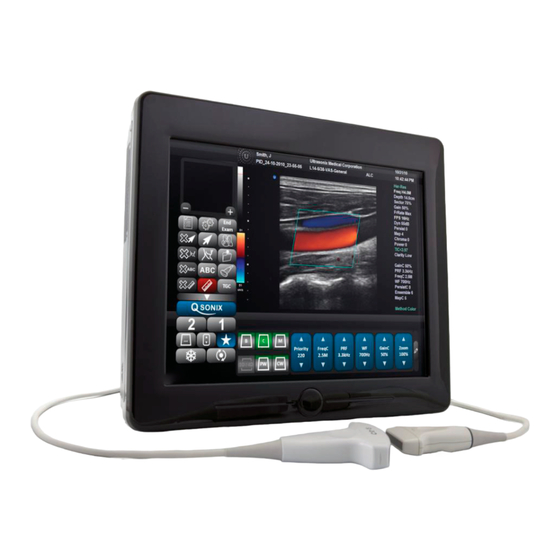
SYSTEM HANDLING Warning: Although the SonixTablet is portable, it weighs more than 30 lbs (13+ kg). To avoid injury, be sure to follow proper workplace/ergonomic lifting techniques when transporting the system. LICENSE AGREEMENT Portions of the Sonix computer programs have been patented by Ultrasonix Medical Corporation (Ultrasonix) or are patent... - Page 13 Figure 1-1: SonixTablet Ultrasound System Table 1-1: SonixTablet Ultrasound System LCD Display/Touch Screen Folding Carry Handle (top) Side Connectivity Panel (power and Network connections, USB and sound ports) and Hard Drive access Speaker Transducers (connected at rear of system) Warning: Do not place the device on any surface that blocks/restricts ventilation (e.g., do not set the device on a soft surface such as a bed).
-
Page 14: Physical Description
The modulo, which is the heart of the system, is enclosed in the case with the LCD display/touch screen. The 1.10.4 Transducers Ultrasonix offers a wide selection of high performance transducers for a variety of imaging applications. Incorporating the latest acoustic materials and technology, these lightweight transducers are ergonomic and durable for maximum clinical use. -
Page 15: Chapter 2: System Specifications
Argentina ......... 220V Guinea ..........220V Peru ...........110/220V Aruba ..........110V Guyana ..........110V Philippines .........110/220V Australia .......... 240V Haiti ..........110V Poland ..........220V Austria ..........220V Honduras ..........110V Portugal ........110/220V Azores ........110/220V Hong Kong ........220V Puerto Rico........110V SonixTablet Service Manual 00.053.129, Revision C Chapter 2: System Specifications... - Page 16 Ghana..........220V Norway ..........220V Zambia ..........220V Gibraltar........... 220V Okinawa ...........110V Zimbabwe........220V Caution: Ensure the correct voltage rating has been selected before turning system ON. Contact an Ultrasonix Technical Support Representative if the appropriate voltage rating is not listed here (Table 2-4, above).
-
Page 17: Chapter 3: System Installation
Warning: Operate in an indoor environment only, free from moisture, flammable liquids, gases, corrosive substances, strong electrical or magnetic fields and equipment that generates high frequency waves. Ultrasonix cannot guarantee the proper performance of the system if used in the above-listed conditions. Table 3-2: Barcode Reader Operating Temperature 32º... -
Page 18: Electrical Requirements
100-120V ~, 50/60Hz CSA & UL approved 250Vac, 15A, 3 wire, 18 AWG, grounding type, 6-15P Hospital Grade plug cap, less than 6 m long, 200-240V~, 50/60Hz CSA & UL approved Chapter 3: System Installation 00.053.129, Revision C SonixTablet Service Manual... -
Page 19: Electrostatic Discharge
Warning: The system should not be used adjacent to or stacked with other equipment. If adjacent or stacked use is necessary, the system should be observed in order to verify normal operation in the configuration in which it will be used. SonixTablet Service Manual 00.053.129, Revision C Chapter 3: System Installation... -
Page 20: Wiring Requirements
Caution: System networking options are intended for use inside your organization's firewall. Organizations that elect to configure/use the networking functionality provided by Ultrasonix are assuming all liabilities and risks associated with that decision. 3.1.5.3 Image Management Network Obtain the following information from the system administrator: •... -
Page 21: Pre-Installation
To Inspect the Shipping Crate and Box Upon Arrival: Examine the shipping container(s) for any damage that may have occurred during transport. Look for evidence to ensure that the carton has not been opened. Report any damage to both the carrier and Ultrasonix. 3.2.2 SonixTABLET Unpacking Instructions Equipment/Tools Required: •... - Page 22 Carefully remove the SonixTablet and the foam packing in one piece, setting it gently on a solid, flat surface. Warning: Although the SonixTablet is portable, it weighs more than 30 lbs (13+ kg). To avoid injury, be sure to follow proper workplace/ergonomic lifting techniques when transporting the system.
- Page 23 Two (2) or Three (3) One (1) Transducer Transducers Note: The transducer packing carton will vary in size, depending on whether it contains, one (1), two (2) or three (3) transducers. SonixTablet Service Manual 00.053.129, Revision C Chapter 3: System Installation...
-
Page 24: Installation
Caution: The system voltage setting is configured in the factory. It should not need to be changed in the field. Figure 3-2: EMI Filter Figure 3-3: EMI Filter and System Power Button Location Power Cord (to Wall Outlet) Receptacle Main Power Switch Chapter 3: System Installation 00.053.129, Revision C SonixTablet Service Manual... - Page 25 Position the screwdriver at the top (as in step 2), using it to remove the fuse box. Flip the fuse box and reinsert it so the correct voltage is visible. Close the fuse box lid. SonixTablet Service Manual 00.053.129, Revision C Chapter 3: System Installation...
-
Page 26: Powering The System
Caution: DO NOT use Main Power switch for regular power shut downs. Failure to follow the correct procedure may result in loss of patient data and/or hard drive failure. Chapter 3: System Installation 00.053.129, Revision C SonixTablet Service Manual 3-10... -
Page 27: Changing Fuses
Replace one or both fuses, as required. Reinsert the fuse box. Caution: Ensure the correct voltage setting is visible and that it matches the setting on the EMI filter (3.3.1.1). Close the fuse box lid. SonixTablet Service Manual 00.053.129, Revision C Chapter 3: System Installation 3-11... -
Page 28: Transducer Inspection
3.3.4 System Initialization To Initialize the System: Inspect the system for scratches or damage. Note any damage to the system and report it to Ultrasonix. Connect at least one transducer to the system. Plug in the power cord. Press and hold the console POWER button for one (1) second. -
Page 29: Peripherals
3.3.5 Peripherals Unpack and inspect all peripherals included with the system. Itemize any problems, record the model and serial numbers and report the damage to Ultrasonix. To connect/configure the printer, refer to Chapter 6: Peripherals and Accessories. 3.3.5.1 Barcode Reader To connect the barcode reader, plug the reader's USB connector into one (1) of the four (4) USB ports on the system. - Page 30 Chapter 3: System Installation 00.053.129, Revision C SonixTablet Service Manual 3-14...
-
Page 31: Chapter 4: Performance Testing
Figure 4-1: Console (LCD Display/Touch Screen) Menu Transducer QSONIX Imaging Parameters Mode Favorites Freeze Update Note: Between each test, return the system to B-Mode. (Tap the touch screen button - if necessary, tap first.) SonixTablet Service Manual 00.053.129, Revision C Chapter 4: Performance Testing... -
Page 32: Image Test
The following comprises a list of the supported removable hardware: • medical grade USB printer • medical grade Footswitch • barcode reader • USB media (memory stick, external hard drive, etc.). Chapter 4: Performance Testing 00.053.129, Revision C SonixTablet Service Manual... -
Page 33: Pulsed Doppler Sound Test
To Check System Licensing: Tap the touch screen button. Select Administrator > Licensing. If none of the licenses are Active, reload license.key following the instructions in section Chapter 10: License.txt Importation. SonixTablet Service Manual 00.053.129, Revision C Chapter 4: Performance Testing... - Page 34 Chapter 4: Performance Testing 00.053.129, Revision C SonixTablet Service Manual...
-
Page 35: Chapter 5: Software
Select Administrator > Software Updates. The system will default to the Update Location "Internet Update". From the Available Updates drop-down menu, select the appropriate software version. Note: Consult with an Ultrasonix Technical Support Representative in order to determine which version to install. Select Update. -
Page 36: Software Update Via A Downloaded File
If your system does not connect directly to the Internet, but you have a computer with access to an Internet connection, the update can be downloaded from the Ultrasonix website and copied to the root of a USB device (memory stick, external hard drive, etc.). -
Page 37: Patient Database Repair
Select OK to exit. SYSTEM RECOVERY Before performing a system recovery, consult an Ultrasonix Technical Support Representative as this should only be done as a last resort. Technical Support will provide you with the appropriate documentation to carry out a system recovery. - Page 38 Chapter 5: Software 00.053.129, Revision C SonixTablet Service Manual...
-
Page 39: Chapter 6: Peripherals And Accessories
CHAPTER 6: PERIPHERALS AND ACCESSORIES PERIPHERAL COMPONENTS Caution: Refer to the most recent price list to determine the exact make(s)/model(s) of Ultrasonix-approved devices. 6.1.1 Local Printer Setup To Connect the USB Printer: Ensure the printer has been installed. Connect the peripheral power cord to a wall outlet. - Page 40 Select the appropriate shared (network) printer and select Next. Select Yes to continue. Select Yes to set the selected printer as the default. Select Next to print a test page. Select Finish to complete the installation. Chapter 6: Peripherals and Accessories 00.053.129, Revision C SonixTablet Service Manual...
-
Page 41: Configuring Custom Keys
Note: If Trigger is not accessible (i.e., grayed out), deselect Record CINE, then select Trigger. To print a test image on the thermal printer, tap the relevant touch screen button. SonixTablet Service Manual 00.053.129, Revision C Chapter 6: Peripherals and Accessories... -
Page 42: Image Sheet Printing
Custom Keys. To send partial print pages (e.g., 3 images remaining on a 4 image/sheet format) at the end of an exam, tap the touch screen End Exam button. Chapter 6: Peripherals and Accessories 00.053.129, Revision C SonixTablet Service Manual... -
Page 43: Accessories
ACCESSORIES 6.2.1 Transducers Certain transducers may not be available in all markets. Consult your local Ultrasonix Authorized Distributor or Sales Representative to determine availability in your area. Table 6-2: :Transducers BPC8-4/10 (Curved Array) SA4-2/24 (Phased Array) BPL9-5/55 (Linear Array) PA7-4/12 (Phased Array) - Page 44 Chapter 6: Peripherals and Accessories 00.053.129, Revision C SonixTablet Service Manual...
-
Page 45: Chapter 7: Field Service Components
This will ensure access to this data if either the modulo or hard drive needs replaced during servicing. The following options are available for export: Note: When creating a backup prior to servicing or replacing the modulo, Ultrasonix recommends selecting all options for Export. - Page 46 Select Administrator > System > Export…. Check the item(s) to be exported. Note: When creating a backup prior to servicing or replacing the modulo, Ultrasonix recommends selecting all options for Export. Use Select All to check all items and Clear All to clear all checkboxes in one step.
-
Page 47: Importing User Data (As Required)
• DICOM Server Configuration • Settings • Measurement Order • Obstetrical Tables • Protocols • General Note: General is the only Protocol available on SonixTablet systems. • Preset Assignments • Measurement Customization • Worksheets • Banners • SonixHUB Worksheets • General Protocol. - Page 48 • USB media (memory stick, external hard drive, etc.) containing previously exported data. To Import User Data from a Backup: Caution: Ultrasonix does not recommend importing user-defined Presets created with a previous software version as they may not be compatible for use with a more recent software update.
-
Page 49: Exporting Patient/Exam Data (As Required)
If Patient/Exam data is exported using these instructions (7.1.3), it will not be necessary to use the Backup option (7.1.5). Equipment/Tools Required: • USB media (memory stick, external hard drive, etc.). To Export all Patient/Exam Data Using SonixTABLET Software: Tap the touch screen button. Select Import/Export. -
Page 50: Importing Patient/Exam Data (As Required)
When the Import is complete, the following message will be presented. Note: If the data selected for Import is already available on the system, it will not be imported, i.e., it will not overwrite the existing data. Chapter 7: Field Service Components 00.053.129, Revision C SonixTablet Service Manual... -
Page 51: Backing Up/Exporting Patient Data Via The Service Mode Option
Connect the USB storage device to the one of the three (3) remaining USB ports. Tap the touch screen button. Select Administrator > Service…. Type in the Service Mode Password using the USB keyboard. Select OK. SonixTablet Service Manual 00.053.129, Revision C Chapter 7: Field Service Components... - Page 52 If the USB device already contains patient data, the following message will be displayed. Select OK to continue or Cancel to exit without creating a backup. Once the procedure is complete, the following message will be presented. Select OK to continue. Chapter 7: Field Service Components 00.053.129, Revision C SonixTablet Service Manual...
-
Page 53: Restoring/Importing Patient Data Via The Service Mode Option
Type in the Service Mode Password using the USB keyboard. Select OK. From the Advanced Tools and Options drop-down menu, select Patient Data Backup/Restore. Select Go. Note: The system will auto-detect the USB storage device. SonixTablet Service Manual 00.053.129, Revision C Chapter 7: Field Service Components... - Page 54 When Patient/Exam data already exists on the system, a final warning will be presented. Select Yes to continue or No to exit without restoring Patient/Exam data. Once the Restore procedure is complete, the following message will be presented. Select OK to continue. Chapter 7: Field Service Components 00.053.129, Revision C SonixTablet Service Manual 7-10...
-
Page 55: Connectivity
The Side Connectivity Panel can be accessed from the side of the system. The connectors are routed internally enabling easy configuration. 7.1.7.1 Side Connectivity Panel Figure 7-2: Side Connectivity Panel Table 7-3: Side Connectivity Panel Line-in (blue): may be used to connect an Ultrasonix-approved audio input device. Sound System Speaker connection ( green Connections System Microphone connection: Disabled. -
Page 56: Internal Component Replacement
(for example, Federal Privacy Act or the Health Insurance Portability & Accountability Act (HIPAA)). In order to ensure regulatory compliance, Ultrasonix will not remove the system hard drive – and the patient data it contains – from the customer site. - Page 57 Using a # 1 Phillips screwdriver, remove the two (2) screws and washers securing the hard drive cover plate. Using your fingers, pull the relevant hard drive from its slot. SonixTablet Service Manual 00.053.129, Revision C Chapter 7: Field Service Components...
-
Page 58: Replacing The Hard Drives
Replace the hard drive cover plate and, using a # 1 Phillips screwdriver, fasten it with the two (2) screws and washers. Replace the hard drive cover and, using a 2.5mm Allen key, fasten it with the two (2) screws. Chapter 7: Field Service Components 00.053.129, Revision C SonixTablet Service Manual 7-14... -
Page 59: Barcode Reader Servicing
The barcode reader is configured to system requirements prior to shipping with the system. If it becomes necessary to reconfigure it in the field, Ultrasonix Technical Support will provide a copy of the appropriate documentation. Additionally, the manufacturer's User's Guide is included with the system's paperwork. Refer to... -
Page 60: Transducer Testing
Figure 7-3 for an example of an acceptable transducer image. If there is any doubt about the image, contact Ultrasonix Technical Support and forward them a digital copy of the image in question for verification of the diagnosis. Chapter 7: Field Service Components 00.053.129, Revision C... -
Page 61: Testing The Transducer Board
Figure 7-3 for an example of an acceptable transducer image. If there is any doubt about the image, contact Ultrasonix Technical Support and forward them a digital copy of the image in question for verification of the diagnosis. Figure 7-3: Acceptable Transducer Test Image... -
Page 62: Miscellaneous Parts
The transducer holder with integrated cable hook mounts to a table edge with a simple screw clamp. No tools are required. Note: For best results, Ultrasonix recommends removing the transducer holders before cleaning (11.2.6). This will allow the operator to clean all the various curves and folds in a more effective manner. -
Page 63: Chapter 8: Dicom
Beginning with software version 5.5.0, DICOM Structured Reporting is supported. Refer to Table 8-2 for Structured Reporting data transfer options. Figure 8-1: DICOM Configuration Note: Global Settings for the Local Host apply to DICOM Storage, Print and Worklist. SonixTablet Service Manual 00.053.129, Revision C Chapter 8: DICOM... -
Page 64: Dicom Configuration
Use to access specific DICOM Storage, Print and Worklist settings. Worklist... To Configure the Global DICOM Settings: Tap the touch screen button. Select Administrator > DICOM. Configure the global settings as required. Chapter 8: DICOM 00.053.129, Revision C SonixTablet Service Manual... -
Page 65: Dicom Storage Settings
Note: In addition to the four (4) tabbed settings options, select the Settings... button to access Storage Settings. The DICOM Storage AE Configuration dialog enables configuration of AE properties. Figure 8-3: DICOM Storage Settings – AE Configuration SonixTablet Service Manual 00.053.129, Revision C Chapter 8: DICOM... - Page 66 Select to send verification request to DICOM Storage Commitment Device (ping to verify Test connection). Enables the insertion of text symbol(s) not available on the keyboard (e.g., punctuation, Insert (Symbol) symbols and letters from other languages). Chapter 8: DICOM 00.053.129, Revision C SonixTablet Service Manual...
- Page 67 Store Grayscale Images Select to store images in grayscale format. Enables the insertion of text symbol(s) not available on the keyboard (e.g., Insert (Symbol) punctuation, symbols and letters from other languages). SonixTablet Service Manual 00.053.129, Revision C Chapter 8: DICOM...
- Page 68 Note: If a value is specified, the AE Configuration and Storage Commitment dialogs are disabled – images can not be stored to an SCP. Enables the insertion of text symbol(s) not available on the keyboard (e.g., punctuation, symbols and Insert (Symbol) letters from other languages). Chapter 8: DICOM 00.053.129, Revision C SonixTablet Service Manual...
- Page 69 Note: To adjust the Brightness/Contrast settings, position the trackball arrow over the Brightness or Reset Contrast slider. Press and hold the button while moving the trackball left or right to the desired position. SonixTablet Service Manual 00.053.129, Revision C Chapter 8: DICOM...
- Page 70 Select to send Cine files in AVI format. When deselected, Cine files will be sent in DICOM Embed Cine As Is format. Send SonixVCR Videos Select/deselect in order to include/exclude SonixVCR videos in the SonixHUB transfer. Chapter 8: DICOM 00.053.129, Revision C SonixTablet Service Manual...
-
Page 71: Dicom Print Settings
Note: In addition to the two (2) tabbed settings options, select the Settings... button to access Print Settings and Advanced Print Settings. The DICOM Print AE Configuration dialog enables configuration of AE properties. Figure 8-8: DICOM Print Settings – AE Configuration SonixTablet Service Manual 00.053.129, Revision C Chapter 8: DICOM... - Page 72 IP Address Unique identifier of Print SCP. Port Listening Port of the Print SCP. Enables the insertion of text symbol(s) not available on the keyboard (e.g., punctuation, symbols and Insert (Symbol) letters from other languages). Chapter 8: DICOM 00.053.129, Revision C SonixTablet Service Manual 8-10...
- Page 73 Select the type of medium on which the images will be printed: Paper, Clear Film or Blue Print Priority Select the print job priority: High, Medium or Low. Film Destination Select the location to which the print job will be sent: Processor or Magazine. SonixTablet Service Manual 00.053.129, Revision C Chapter 8: DICOM 8-11...
- Page 74 Image Size Enter the printer-specific Image Size in mm. Enables the insertion of text symbol(s) not available on the keyboard (e.g., punctuation, Insert (Symbol) symbols and letters from other languages). Chapter 8: DICOM 00.053.129, Revision C SonixTablet Service Manual 8-12...
- Page 75 Note: To adjust the Brightness/Contrast settings, position the trackball arrow over the Brightness or Reset Contrast slider. Press and hold the button while moving the trackball left or right to the desired position. SonixTablet Service Manual 00.053.129, Revision C Chapter 8: DICOM 8-13...
-
Page 76: Dicom Worklist Settings
IP Address Unique identifier of Worklist SCP. Port Listening Port of the Worklist SCP. Enables the insertion of text symbol(s) not available on the keyboard (e.g., punctuation, symbols and Insert (Symbol) letters from other languages). Chapter 8: DICOM 00.053.129, Revision C SonixTablet Service Manual 8-14... -
Page 77: Chapter 9: Network Configuration
The system can be configured to connect to the local network, either through a hard-wired LAN or Dialup connection. Note: A dialup connection requires a third-party, USB modem. Contact your dealer or Ultrasonix Technical Support to learn more about this option. - Page 78 Enter the Outgoing (SMTP) Server Address here. Server Port Enter the Outgoing Server Port number here. Note: Ultrasonix recommends that Network connections be configured using the settings provided by your IT Department. Chapter 9: Network Configuration 00.053.129, Revision C SonixTablet Service Manual...
-
Page 79: Ethernet (Lan) Network Configuration
To Perform an Ethernet (LAN) Communication Test: Tap the touch screen button. Select Online Support. This should connect the system to an Ultrasonix Technical Support Representative. Note: It may be necessary to restart in order for the changes to take affect. SonixTablet Service Manual 00.053.129, Revision C... -
Page 80: Dialup Network Configuration (If Available)
9.1.2 Dialup Network Configuration (If Available) Note: A dialup connection requires a third-party, USB modem. Contact your dealer or Ultrasonix Technical Support to learn more about this option. Figure 9-3: Network Configuration Page (Dialup) To Configure a Dial-up Connection (If Available): Connect the modem's USB connector to the System Case Connectivity Panel (refer to 7.1.7 Connectivity... -
Page 81: Wireless Configuration
Wireless Signal Strength Indicator Notes: Wireless Network Connection options are controlled by MS Windows, not Ultrasonix. Once a secured, wireless network is in place, it will be necessary to obtain the institution's Network Key (from the IT department) in order to log in. -
Page 82: Wireless Communication Test
To Perform a Wireless Communication Test: Tap the touch screen button. Select Online Support. This should connect the system to an Ultrasonix Technical Support Representative. Note: It may be necessary to restart in order for the changes to take affect. Chapter 9: Network Configuration 00.053.129, Revision C... -
Page 83: Remote Support
REMOTE SUPPORT Remote Support allows Ultrasonix Technical Support to view and control the Sonix for diagnostic purposes. In order to use Remote Support, the Network must be configured (9.1) and a PIN (Personal Identification Number) must be obtained from Ultrasonix Technical Support. - Page 84 Chapter 9: Network Configuration 00.053.129, Revision C SonixTablet Service Manual...
-
Page 85: Chapter 10: License.txt Importation
Select Administrator > Licensing. Make note of the System Identification Number shown in the Licensing window and forward it to Ultrasonix Technical Support to obtain a license.txt file. When the license.txt file arrives, copy it to some form of USB media. -
Page 86: Re-Import License.txt
Under the Look in drop-down menu, select the drive containing license.txt (for example, data_1 (D:)). Highlight license.txt and select Open to re-import the file. Note: If there are any problems, clear all menus, return to the Licensing dialog and contact Ultrasonix Technical Support for assistance. -
Page 87: Chapter 11: Maintenance
System Fans Six (6) months Check for good air flow without excessive noise. Periodic As prescribed by To be performed only by qualified service personnel. Maintenance (PM) Ultrasonix procedures SonixTablet Service Manual 00.053.129, Revision C Chapter 11: Maintenance 11-1... -
Page 88: System Cleaning
11.2 SYSTEM CLEANING Ultrasonix recommends the following cleaning instructions for all external surfaces, including the cart, cables and connectors. Cautions: Power off and unplug the system before cleaning. Do not spill or spray water on the controls, transducer connection receptacle, or transducer ports. -
Page 89: Power Cord(S)
Apply a small amount of one of the following recommended cleaning solutions to a soft, non-abrasive cloth and wipe the wireless adapter: • water • mild detergent (PH level at or near 7) and water solution. SonixTablet Service Manual 00.053.129, Revision C Chapter 11: Maintenance 11-3... -
Page 90: Transducer Holders And Cable Hooks
Power off and unplug the system prior to cleaning. For best results, Ultrasonix recommends removing the transducer holders and cable hooks before cleaning (7.5.1). This will allow the operator to clean all the various curves and folds in a more effective manner. -
Page 91: Cleaning The System Filter
Unscrew the two (2) thumbscrews and washers. Push the filter forward (following the directional arrow label) then lift up. Slide Vacuum thoroughly and gently reinstall the filter. Plug in and power on the system. SonixTablet Service Manual 00.053.129, Revision C Chapter 11: Maintenance 11-5... -
Page 92: Transducer Maintenance
11.3.1 Usage Guidelines Ultrasonix recommends inspecting the transducers prior to each use: • Ensure the transducers are always clean before they are used. There must be no ultrasound gel (from previous imaging), any debris, films or unusual odors present. -
Page 93: Ultrasound Coupling Gels
11.3.2 Ultrasound Coupling Gels The following ultrasound coupling gels are recommended for use with Ultrasonix transducers: Table 11-2: Recommended Ultrasound Coupling Gels Gel Name Manufacturer Address 286 Eldridge Road Fairfield, NJ, 07004 Aquasonic 100 Parker Laboratories, Inc. Ph (800) 631-8888... -
Page 94: General Transducer Maintenance
DO NOT use sterilization or disinfection methods that have not been recommended by Ultrasonix. Severe damage will result. Contact Ultrasonix if you have any doubt about sterilization or disinfection methods. Use of non- recommended cleaning agents may cause damage to the housing and will void transducer warranties. -
Page 95: General Transducer Cleaning/Disinfecting Recommendations And Warnings
(Table 11-3 Table 11-4). They have been tested and determined safe to use on Ultrasonix transducers. Failure to follow these instructions may cause damage and will void transducer warranties. Reprocessing should be completed only by personnel thoroughly trained in proper cleaning/disinfection procedures. -
Page 96: Cleaning/Disinfecting Non-Invasive Transducers
L14-5W/60 Caution: Use only Ultrasonix recommended cleaners/disinfectants (Table 11-3). They have been tested and determined safe to use on Ultrasonix transducers. Failure to follow these instructions may cause damage and will void transducer warranties. Chapter 11: Maintenance 00.053.129, Revision C... -
Page 97: Cleaning Non-Invasive Transducers
Caution: Do not allow cleaning solutions to air dry on the transducer. 11.3.5.2 Disinfecting Non-Invasive Transducers Using a disinfecting agent from the list in Table 11-3, follow the manufacturer’s instructions to disinfect the transducer. SonixTablet Service Manual 00.053.129, Revision C Chapter 11: Maintenance 11-11... -
Page 98: Cleaning/Disinfecting Endocavity Transducers
Caution: Use only Ultrasonix recommended cleaners/disinfectants (Table 11-4). They have been tested and determined safe to use on Ultrasonix transducers. Failure to follow these instructions may cause damage and will void transducer warranties. To Clean/Disinfect a Transducer: Unplug the transducer. -
Page 99: Sterilization
• the transducer is properly packaged for shipment (11.3.3.2) • all shipping waybills/paperwork is completed as per the relevant regulations and laws. Refer to 7.6 Returning Parts for Service/Repair/Replacement for more details on transducer return or replacement. SonixTablet Service Manual 00.053.129, Revision C Chapter 11: Maintenance 11-13... - Page 100 Chapter 11: Maintenance 00.053.129, Revision C SonixTablet Service Manual 11-14...
-
Page 101: Chapter 12: Troubleshooting Issues
CHAPTER 12: TROUBLESHOOTING ISSUES In addition to the issues discussed in this chapter, there may be other relevant topics available on the Ultrasonix Knowledge Base. To login to an existing account or register for a new one, follow this link: http://www.ultrasonix.com/user/login. -
Page 102: System Seems Slow
12.5 SYSTEM SEEMS SLOW System may be overheating: • Check the CPU fan to ensure that it is working properly. If it is not, it will have to be replaced by a qualified Ultrasonix Service Technician. There may be issues with the RAM: •... -
Page 103: Image Is Grainy Or Missing
Check to ensure the transducer is not defective: • test the transducer on another system and compare images • submit test images for diagnosis to Ultrasonix Technical Support. 12.8 IMAGE HAS BLACK OR DARK AREAS Black or dark areas on an ultrasound image are usually caused by dead elements in or delamination of the transducer. The problem may be caused by either the transducer or the transducer MUX board, so both may have to be tested. -
Page 104: Image Has Wavy Interference
To mitigate wavy interference on the ultrasound image, ensure: • the Ultrasonix system is the only device connected to a dedicated wall outlet. (Sharing a wall outlet with other devices that emit magnetic interference - such as an X-ray machine, computer server or halogen light - can cause noise on the power line which interferes with the ultrasound image.) -
Page 105: Initialization Failures
Initialization fails due to a DL Memories Test error. If a restart does fix the problem, check the RX Module board: • A.7.2 Failed DL Memories Test. 12.13.4 Connecting to Console Failure (at Initialization) If restarting the system does not resolve the issue, contact Ultrasonix Technical Support. SonixTablet Service Manual 00.053.129, Revision C Chapter 12: Troubleshooting Issues 12-5... -
Page 106: System Hangs When Loading Maps (At Initialization)
12.13.6 Successful Initialization but only 4DC7-3/40 Transducer is Detected If the system passes all error checks during initialization, but no transducers are detected except the 4DC7-3/40 (if it is connected), contact Ultrasonix Technical Support. 12.14 NO NETWORK CONNECTION VIA ETHERNET CABLE If the system is connected to the network via an Ethernet cable but a network connection cannot be established, there may be an issue with the network cable connection or with the BIOS. -
Page 107: Appendix A: Troubleshooting Solutions
If the system still does not power up, follow the remaining suggestions in Appendix 12.1 before contacting Ultrasonix for further instructions. SYSTEM POWERS ON, LCD DISPLAY SHOWS MBR ERROR 1 To Resolve the MBR Error 1 Issue: Power down and unplug the system. -
Page 108: Check Dicom Settings
Delete Older LUTS Files Ensure a USB keyboard is connected to the system. Press the WINDOWS START KEY and select All Programs > Accessories > Windows Explorer. Navigate to D:\Ultrasonix Settings\LUTS. Delete the LUTS file. A.3.6 Delete Older LOG Files Ensure a USB keyboard is connected to the system. -
Page 109: Image Is Grainy
Under the Look in drop-down menu, select the relevant drive/device and locate license.txt. Select Open to re-import license.txt. Note: If there are any problems, clear all menus, return to the Licensing dialog and contact Ultrasonix Technical Support for assistance. SonixTablet Service Manual 00.053.129, Revision C... -
Page 110: Image Has Three (3) Uniform Black Areas (Left, Middle, Right
Press the WINDOWS START KEY and select. Type regedit and press Enter. In the registry go to HKEY_CURRENT_USER > Software > Ultrasonix > Exam > Settings. Make the changes advised by the Ultrasonix Technical Support Representative. Appendix A: Troubleshooting Solutions 00.053.129, Revision C... -
Page 111: Initialization Failures
Press the WINDOWS START KEY again and open Notepad (Start > Programs > Accessories > Notepad). Use ALT+TAB on the USB keyboard to cycle between the Exam, Notepad, and Windows Explorer. In Windows Explorer, go to C:\Program files\Ultrasonix\Exam and double-click Hwtest.exe. Select Initialize and wait for the results. -
Page 112: Failed Dl Memories Test
Note: Up to 30 TX lines are visible at one time. To view any TX line greater than 30, set the TX Line Parameter to a higher number (e.g., 60.) TX Lines go from 0 to 127. Select Apply Changes. Record the findings in Notepad and send a copy of the file to an Ultrasonix Technical Support Representative. A.7.2 Failed DL Memories Test To Test the RX Module: Disconnect all transducers. -
Page 113: Network Connection Via Ethernet Cable
Select Use the following IP address and enter the relevant information. Select OK and exit. Note: It may be necessary to restart in order for the changes to take affect. SonixTablet Service Manual 00.053.129, Revision C Appendix A: Troubleshooting Solutions... -
Page 114: Transducer Connection Port Not Functioning
TRANSDUCER CONNECTION PORT NOT FUNCTIONING To Confirm MUX Board Needs Replacing: Disconnect all transducers. Reconnect only one (1) transducer. Restart the system. If the transducer still isn’t functioning, contact Ultrasonix Technical Support. Appendix A: Troubleshooting Solutions 00.053.129, Revision C SonixTablet Service Manual... -
Page 115: Appendix B: Electromagnetic Immunity Tables
Guidance and Manufacturer’s Declaration — Electromagnetic Immunity SonixTABLET Ultrasound Systems are intended for use in the electromagnetic environment specified below. The customer or the user of the SonixTABLET Ultrasound System should ensure that it is used in such an environment. - Page 116 Table B-3: EN 60601-1-2:2001 (Table 204) Guidance and Manufacturer’s Declaration—Electromagnetic Immunity The SonixTABLET Ultrasound System is intended for use in the electromagnetic environment specified below. The customer or the user of the SonixTABLET Ultrasound System should ensure that it is used in such an environment.
-
Page 117: Appendix C: Ultrasonix Limited Warranty
APPENDIX C: ULTRASONIX LIMITED WARRANTY The following is excerpted from Section 8 of the Standard Terms and Conditions of Sales for Ultrasonix Medical Corporation (QF 72- 01E). Refer to the original document for complete details. LIMITED WARRANTY AND REMEDY LIMITED WARRANTY... - Page 118 Appendix C: Ultrasonix Limited Warranty 00.053.129, Revision C SonixTablet Service Manual...
-
Page 119: Appendix D: Service Drawings
APPENDIX D: SERVICE DRAWINGS Caution: Service drawings do not include cable connections. Please refer to the relevant sections in this Service Manual for details on cables. SonixTablet Service Manual 00.053.129, Revision C Appendix D: Service Drawings... - Page 120 Appendix D: Service Drawings 00.053.129, Revision C SonixTablet Service Manual...
- Page 121 Patient Data Hard Drive UXID: 00.031.321 UXID: 00.034.105 Tool: 2.5mm Allen key Solid State Hard Drive UXID: 00.034.097 M3 x 6 Pan Head Screw (x2) UXID: 00.031.103 Tool: #1 Phillips Screwdriver SonixTablet Service Manual 00.053.129, Revision C Appendix D: Service Drawings...
- Page 122 UXID: 00.031.321 UXID: 00.034.105 Tool: 2.5mm Allen key Solid State Hard Drive UXID: 00.034.097 M3 x 6 Pan Head Screw with intergrated washer (x2) UXID: 00.031.404 Tool: #1 Phillips Screwdriver SonixTablet Service Manual 00.053.129, Revision C Appendix D: Service Drawings...
- Page 123 UXID: 00.031.400 Caution: Before removing the filter, gently lay the system face down on a protective mat (such as bubble wrap or a soft towel). Air Filter UXID: 00.032.194 Slide SonixTablet Service Manual 00.053.129, Revision C Appendix D: Service Drawings...
Need help?
Do you have a question about the SonixTablet and is the answer not in the manual?
Questions and answers
Dove si trova la batteria da sostituire 2032